AMWUT395CB TRANSCEIVER WITH WEATHER ALERT
Uniden America Corporation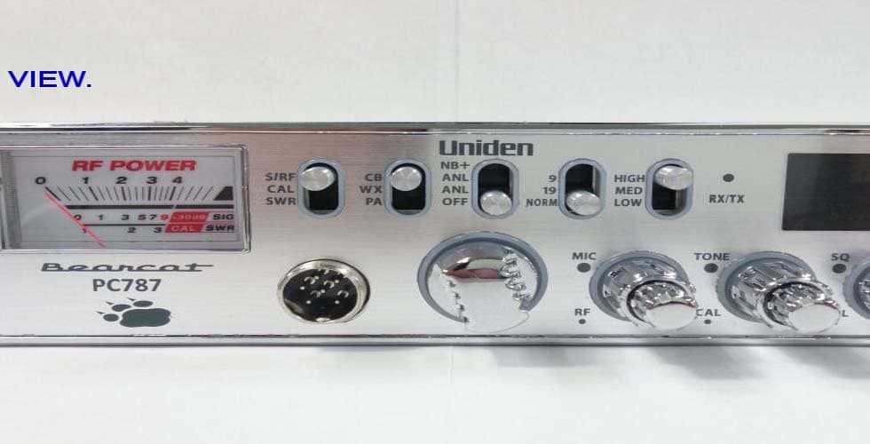
Click to zoom
Application Details
- Equipment Class
- TNB - Licensed Non-Broadcast Station Transmitter
- Date of Grant
- Aug 12, 2013
- Application Purpose
- Original Equipment
- Date of Application
- Aug 12, 2013
- Equipment Note
- CB TRANSCEIVER WITH WEATHER ALERT
- Frequency Range
- 26.96500000 - 27.40500000
- Company
- Uniden America Corporation
- Country
- United States
Documents & Files
Document Text
Text extracted from the exhibit documents filed with the FCC. Open a document above to read the original.
Users Manual
Owner’s Manual Printed in Vietnam U01UT393ZZZ(0) ® PC787 Contents sAFetY notICe ..........................................................................4 UnpACkIng ................................................................................4 DesCrIptIon .............................................................................5 FeAtUres ......................................................................................................5 emergenCY operAtIon .........................................................6 Controls AnD FUnCtIons ....................................................6 InstAllAtIon ............................................................................8 moBIle InstAllAtIon ..............................................................................8 Mobile Antenna ...........................................................................................9 Wireless CB Microphone Installation (Optional) ........................................9 Connecting the Power Cords ......................................................................9 Ground Information .................................................................................10 UsIng YoUr pC787 ..................................................................10 tUrn pC787 on/oFF ..................................................................................10 CB moDe ......................................................................................................10 Basic Settings ...........................................................................................10 Calibrate Standing Wave Ratio (SWR) .....................................................11 pA moDe ......................................................................................................12 preventIve mAIntenAnCe ..................................................12 mAIntenAnCe .........................................................................13 troUBleshootIng ...............................................................13 servICIng YoUr trAnsCeIver ...........................................14 © 2013 Uniden America Corporation Uniden is a registered trademark of Uniden America Corporation. Bearcat is a registered trademark of Uniden America Corporation. Features, specifications, and availability of optional accessories are all subject to change without notice. speCIFICAtIons .......................................................................14 rADIo CoDe DeFInItIons .....................................................15 10-CoDes .....................................................................................................15 FCC pArt 15 InFormAtIon ...................................................17 two-YeAr extenDeD wArrAntY ......................................17 4 sAFetY notICe The antenna used for this radio must be properly installed and maintained and must provide a separation distance of at least 34 cm (13.4 Inches) from all persons and must not be collocated or operated in conjunction with any other antenna or transmitter. Never transmit if any person is closer than the specified distance to the antenna. Note that Uniden does not specify or supply any antenna with this transceiver. While a 0 dBi gain antenna is normal for a typical installation, the above limit applies to any antenna with up to 3 dBi gain. L’appareil est conforme aux normes d’Industrie Canada. Son fonctionnement est soumis aux deux conditions suivantes : (1) Ce dispositif ne doit pas causer d’interférences et (2), il doit pouvoir accepter les interférences, incluant celles pouvant nuire à son fonctionnement normal. Changes or modifications to this product or use of accessories not expressly approved by Uniden, or operation of this product in any way other than as provided in the Uniden Owner’s Manual could void your authority to operate this product. A complete Owner’s Manual in French can be downloaded from http:// www.uniden.com/. UnpACkIng Your PC787 contains the following: PC787 CB 2-way mobile radio Microphone Mounting Bracket Kit DC Power Cord Reference Guide Part 95 Subpart D (FCC Rules) If any items are missing or damaged, contact your place of purchase immediately. 5 DesCrIptIon Your PC787 represents the highest quality communications device designed for use in the Citizens Band Radio Service. It will operate on any of the 40 AM frequencies authorized by the Federal Communications Commission (FCC). The Citizens Band Radio Service is under the jurisdiction of the Federal Communications Commission (FCC). Any adjustments or alterations which would alter the performance of the transceiver's original FCC type acceptance, or which would change the frequency determining method, are strictly prohibited. Replacement or substitution of crystal, transistors, ICs, regulator diodes, or any other part of a unique nature, with parts other than those recommend by Uniden, may cause violations of the technical regulations in Part 95 of the FCC Rules or in violation of type acceptance requirements in Part 2 of the rules. FeAtUres CB AM 40 channels (4W) 7 weather channels with Weather Alert Public Address function (External speaker required - not provided) Automatic Noise Limiter Noise Blanker Transmit/Receive LED (Red and yellow-green) CH9 and CH19 direct tune Dimmer control (High/Medium/Low) Variable RF Gain Variable MIC Gain Variable Tone control Multifunction Meter (RF, Signal Strength, and SWR) Variable Volume control Variable Squelch control 6-pin microphone jack 6 emergenCY operAtIon 1. Move the 9/19/NORM switch to 9; the radio automatically tunes to Channel 9 and disables the channel selector. 2. Press and hold PTT and speak clearly. Release PTT after speaking. 3. If there is no response, move the 9/19/NORM switch to 19; the radio automatically tunes to Channel 19. 4. Press and hold PTT and speak clearly. Release PTT after speaking. 5. If there is still no response, move the 9/19…
Text truncated - open the document above for the full version.
Parts List/Tune Up Info
FORM-1 EQUIPMENT SETTING PAGE MODELUNITBLOCKISSUE DATEISSUED TITLE ALIGNMENT OF TRANSMITTER SUB TITLE REQUIRED EQUIPMENT AND JIG NO.QTY 1DC POWER SUPPLY116V; >3A 2DC CURRENT METER1 3RF COMMUNICATION TEST SET18920B 60W 4OSCILLOSCOPE2>50MHz 5AF OSCILLATOR1 6AF ATTENUATOR1 7 AC VOLTMETER1 8 MIC/PTT JIG1 9 SWR JIG1 1010:1 RF Probe1 1 JIG AND EQUIPMENT SETTING TOOLS / EQPT REQ'D FOR ADJUSTMENT EQUIPMENT / JIG CONNECTION DIAGRAM(ARIGN. PROCEDURE REF.DIAGRAM FORM4 CAN BE USED) D.U.T RF CommunicationOscilloscope AF OscillatorTest set 1kHz~2.5kHz SWR JIG AF AttenuatorAC Volt (50Ω/100Ω/150Ω) meter 10:1 RF PROBE Oscilloscope MIC/PTT JIG DC CurrentDC Power Supply meter13.8V REV. CODE △△△△△△△△△△△△△ DATE LOT # / RN # REVISED BY CHECKED BY ENGLISH VERSION02.09 JQD818ZF013 R0 △△ REVISONS JIG/EQUIP. MODEL NO. REMARKS (SPEC OF EQUIP.) ALIGNMENT PROCEDURE JIG / EQUIPMENT NAME 1 2013/7/23 PC787W Yamazaki Mic. Jack ANT DC IN TP201 ALIGNMENT PROCEDURE FORM - 3 PAGE MODEL UNIT BLOCKISSUE DATE ISSUED SUB TITLE REF DIAGRAM 1,ALIGNMENT PROCEDURE Connect PTT/MIC JIG (PTT OFF/RX MODE)to MIC JACK FRONT PANEL setting 119 POWER ON, CH set to CB/19 219 PTT SW ON (MIC NO INPUT) Connect RF probe to TP203 L211Adjust L211and L210 to maximum on oscilloscope reading. L210Repeat two times of above. Connect RF probe to TP201 319 PTT SW ON (MIC NO INPUT) L209Adjust L209 to maximum on oscilloscope reading. 419 PTT SW ON (MIC NO INPUT) L204ADJUST RF TX POWER to MAXIMUM L204ADJUST RF TX POWER to 3.65W ±0.05W*1 CHECK DC current; less than 1.5 A CHECK TX FREQ.;27.185MHz +/- 300Hz 519 METER_SW set to S/RFRT201 ADJUST METER TO "4" position PTT SW ON MIC INPUT : NO SIGNAL 619 PTT SW ONCHECK AM MODULATION : 50% or more MIC GAIN : set to MAX MIC INPUT : 1kHz / 1mV *1 Adjust L204 to the CW direction from the maximum power position ENGLISH VERSION02.09 JQD818ZF013 R0 TITLEALIGNMENT OF TRANSMITTER 2 Yamazaki PC787W 2013/7/23 STEP CH TEST CONDITIONPROCEDURE ADJ. REV. CODE △△△△△△△△△△△△△△ DATE LOT # / RN # REVISED BY CHECKED BY REVISION ●●● ● ● S/RF CBOFF19HI MIC/RF TONE/CALSQ/VOL METER_SW 919_SW L204 CW direction FORM-4 REFERENCE DIAGRAM NO. PAGE MODEL UNIT BLOCKISSUE DATE ISSUED TITLESUB TITLE ADJUSTMENT POINTS REF DIAGRAM B1 PA-485 (TOP VIEW) L204 : TX Power Adjust RT201: TX meter Adjust ENGLISH VERSION 02.09 JQD818ZF013 R0 3 Yamazaki ALIGNMENT OF TRANSMITTER 2013/7/23 PC787W ALIGNMENT PROCEDURE REV. CODE △△△△△△△△△△△△△△ DATE LOT # / RN # REVISED BY CHECKED BY REVISION METER increase METER decrease RT201 TP201 TP201TP201 TP201 RT201 RT201RT201 RT201 L204 L204L204 L204 L209 L209L209 L209 L210 L210L210 L210 L211 L211L211 L211 FORM-1 EQUIPMENT SETTING PAGE MODELUNITBLOCKISSUE DATEISSUED TITLE ALIGNMENT OF RECEIVER SUB TITLE REQUIRED EQUIPMENT AND JIG NO.QTY 1DC POWER SUPPLY115V; >2A 2SIGNAL GENERATOR1 3AC VOLTMETER with Distortion1 48 ohmDUMMY LOAD 1 >5W 5OSCILLOSCOPE1 6DC CURRENT METER1 7 PTT / MIC JIG1 8PULSE GENERATOR1 9 DC VOLT METER2DIGITAL VOLT METER 10AC VOLTMETER 1 JIG AND EQUIPMENT SETTING TOOLS / EQPT REQ'D FOR ADJUSTMENT EQUIPMENT / JIG CONNECTION DIAGRAM(ARIGN. PROCEDURE REF.DIAGRAM FORM4 CAN BE USED) D.U.T 8ΩAC Volt meter DummyDistortion meter Oscilloscope DC Volt meter 50Hz Square wave Pulse Genarator 1Vpp DC Volt meterSSG AC VoltPTT/MICDC CurrentDC Power Supply meterJIGmeter13.8V PTT OFF REV. CODE △△△△△△△△△△△△△ DATE LOT # / RN # REVISED BY CHECKED BY ENGLISH VERSION02.09 JQD818ZF013 R0 REVISONS △△ JIG / EQUIPMENT NAME JIG/EQUIP. MODEL NO. REMARKS (SPEC OF EQUIP.) 2013/7/23 UT3951V 4 Yamazaki ALIGNMENT PROCEDURE DC IN ANT EXT SP Mic. Jack TP103 Audio out 8V ALIGNMENT PROCEDURE FORM - 3 PAGE MODEL UNIT BLOCKISSUE DATE ISSUED ALIGNMENT OF RECEIVERSUB TITLECB ALIGNMENT PROCEDURE REF DIAGRAM 1,ALIGNMENT PROCEDURE Connect PTT/MIC JIG (PTT OFF/RX MODE)to MIC JACK FRONT PANEL setting 120 POWER ON, CH set to CB/20 220 SSG set to 27.205MHz CW(=NO MOD.) -67dBm Adjust RT1 to meter indication "9" METER_SW set to S/RFRT1 20 SSG set to Adjust RT2 at the position where a sound just appears. 3 27.205MHz 1kHz AM30%MOD -47dBm SQ : CWRT2 401 MODE_SW set to WX CH set to WX/01 501 SSG set to Connect volt meter to TP103 162.55MHz CW(=NO MOD.) -47dBm L105Adjust L105 to TP103 voltage 3.0V ±0.3V ENGLISH VERSION02.09 JQD818ZF013 R0 PC787W 5 ADJ. TITLE 2013/7/23Yamazaki TEST CONDITIONPROCEDURESTEP CH REV. CODE △△△△△△△△△△△△△△ DATE LOT # / RN # REVISED BY CHECKED BY REVISION ●●● ●● S/RF CBOFFNOR HI MIC/RFTONE/CALSQ/VOL MODE_SW ●● ● ●● S/RF WXOFFNOR HI MIC/RF TONE/CALSQ/VOL FORM-4 REFERENCE DIAGRAM NO. PAGE MODEL UNIT BLOCKISSUE DATE ISSUED TITLESUB TITLE CB ADJUSTMENT POINTS REF DIAGRAM B1 PA-485 (TOP VIEW) RT1: S meter adjust RT2: CB SQ adjust L105: WX discriminator adjust TP103 : Discri voltage ENGLISH VERSION 02.09 JQD818ZF013 R0 ALIGNMENT OF RECEIVER 2013/7/23 PC787W 6 Yamazaki ALIGNMENT PROCEDURE REV. CODE △△△△△△△△△△△△△△ DATE LOT # / RN # REVISED BY CHECKED BY REVISION RT1 RT1RT1 RT1RT2 RT2RT2 RT2 L105 L105L105 L105 TP103 TP103TP103 TP103
Test Report
Test Report Serial No.: 060713AMW-T1247-E95D Test Report Issue Date: 8/8/2013 Measurement Date(s): 29/06/2013-1/07/2013 Test Report Revision No.: 1.0 Rule Part(s) Applied: FCC 47 CFR §2, §95D, RSS-236, RSS_GEN Test Site Registration(s): FCC Accredited Site Test Lab Certificate No. 2470.01 Applicant: Uniden America Corporation FCC ID: Ind. Can.: AMWUT395 513C-UT395 Model(s): Bearcat PC787W DUT Type: AM Mobile CB Radio Transceiver with Weather Alert Frequency Range: 26.965 - 27.405 MHz 2013 Celltech Labs Inc. This document is not to be reproduced in whole or in part without the prior written permission of Celltech Labs Inc. Page 1 of 32 COMPLIANCE TEST REPORT FCC PART 95D RSS-236 EMC/RF MEASUREMENT REPORT Name CELLTECH LABS INCORPORATED Test Lab Information Address 21-364 Lougheed Road, Kelowna, British Columbia V1X 7R8 Canada Test Lab Accreditation(s) A2LA ISO 17025:2005 (A2LA Test Lab Certificate No. 2470.01) FCC Accredited Site Test Site Registration No. IC 3874A-1 Name UNIDEN AMERICA CORPORATION Applicant Information Address 6225 North State Highway 161, Suite 300 Irving, Texas 75038 FCC Ind. Can. 47 CFR Part 95 Subpart D RSS-236 Measurement Standard(s) & Procedure(s) Applied ANSI TIA/EIA-382-A C63.4-2003 Device Classification(s) FCC/IC Licensed Non-Broadcast Station Transmitter (TNB) Device RF Exposure Category FCC Mobile Device Identifier(s) FCC ID: Ind. Can. AMWUT395 513C-UT395 Application Type FCC/IC Certification Device Under Test (DUT) Mobile CB Radio Transceiver with Weather Alert Date of Sample Receipt 28 July, 2013 Date(s) of Evaluation 29 July, 2013 – 1 Aug 2013 Device Model(s) Bearcat PC787W Test Sample Serial No.(s) TA Sample - Identical Prototype Transmit Frequency Range(s) 26.965 - 27.405 MHz Channels 1-40 Rated TX Power 4W (36dBm) Modulation Type(s) AM Emission Designator(s) 6K00A3E Antenna External Whip, 0dBi nominal (3dBi maximum). Power Source(s) Tested 12 VDC Battery, DC Power Supply (13.8 V) This wireless device has demonstrated compliance with the applicable technical standards indicated in the measurement report and was tested in accordance with the measurement procedures specified in FCC 47 CFR Rule Parts 2, Part 15B and Part 95D,RSS-236, RSS- GEN ANSI TIA/EIA-382-A and ANSI C63.4-2003. I attest to the accuracy of data. All measurements were performed by me or were made under my supervision and are correct to the best of my knowledge and belief. I assume full responsibility for the completeness of these measurements and vouch for the qualifications of all persons taking them. The results and statements contained in this report pertain only to the device(s) evaluated. This test report shall not be reproduced partially, or in full, without the prior written approval of Celltech Labs Inc. Test Report Approved By Glen Westwell 8/8/2013 Celltech Labs Inc. Test Report Serial No.: 060713AMW-T1247-E95D Test Report Issue Date: 8/8/2013 Measurement Date(s): 29/06/2013-1/07/2013 Test Report Revision No.: 1.0 Rule Part(s) Applied: FCC 47 CFR §2, §95D, RSS-236, RSS_GEN Test Site Registration(s): FCC Accredited Site Test Lab Certificate No. 2470.01 Applicant: Uniden America Corporation FCC ID: Ind. Can.: AMWUT395 513C-UT395 Model(s): Bearcat PC787W DUT Type: AM Mobile CB Radio Transceiver with Weather Alert Frequency Range: 26.965 - 27.405 MHz 2013 Celltech Labs Inc. This document is not to be reproduced in whole or in part without the prior written permission of Celltech Labs Inc. Page 2 of 32 TABLE OF CONTENTS 1.0 SCOPE ................................................................................................................................................................ 5 2.0 REFERENCES .................................................................................................................................................... 5 2.1 Normative References ......................................................................................................................................... 5 3.0 PASS/FAIL CRITERIA......................................................................................................................................... 5 4.0 FACILITIES AND ACCREDITATIONS ................................................................................................................ 6 5.0 GENERAL INFORMATION ................................................................................................................................. 6 5.1 DUT Description & Specifications........................................................................................................................ 6 Appendix A RF Output Power Measurement...................................................................................................... 7 Appendix B Modulation Characteristics (Modulation Limiting)............................................................................ 9 Appendix C Modulation Characteristics (Audio Frequency Response & Low Pass Filter) ............................... 11 Appendix D Occupied Bandwidth and Emission Mask ..................................................................................... 13 Appendix E Spurious Emissions at the Antenna Terminal ............................................................................... 15 Appendix F Radiated Spurious Emissions........................................................................................................ 22 Appendix G Frequency Stability ........................................................................................................................ 27 Appendix H Device Photographs ...................................................................................................................... 29 END OF DOCUMENT ............................................................................................................................................. 32 FIGURES Figure B.5-1 - Setup Drawing – Modulation Characteristics ..............................…
Text truncated - open the document above for the full version.
Contact Information
Applicant
Paul Roby
Test Firm
Celltech Labs Inc.Ben Hewson
Technical Specifications
| # | Rule Parts | Frequency Range | Power Output | Emission | Tolerance |
|---|---|---|---|---|---|
| 1 | 95D | 26.965 MHz - 27.405 MHz | 4 W | 6K00A3E | 0.0050000000 % |
Other Applications from Uniden America Corporation
AMWUA2405
Apr 15, 2026RADAR DETECTOR
Equipment Class
JBP - Part 15 Class B Computing Device PeripheralAMWUA2406
Apr 15, 2026RADAR DETECTOR
Equipment Class
JBP - Part 15 Class B Computing Device PeripheralAMWUA2402
Jul 23, 2024RADAR DETECTOR
Equipment Class
CRD - Part 15 Radar Detector
AMWUA2404
Feb 17, 2024Wi-Fi Bluetooth Combo Module
Equipment Class
DTS - Digital Transmission System
AMWUA2301
Feb 15, 2023RADAR DETECTOR
Equipment Class
CRD - Part 15 Radar Detector