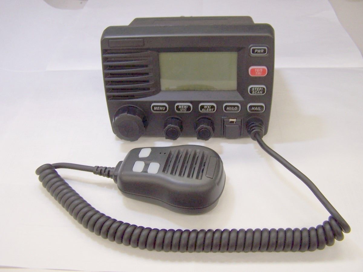
AMWUT601Marine VHF Radio (GMDSS) with Wireless Mircrophone
Uniden America Corporation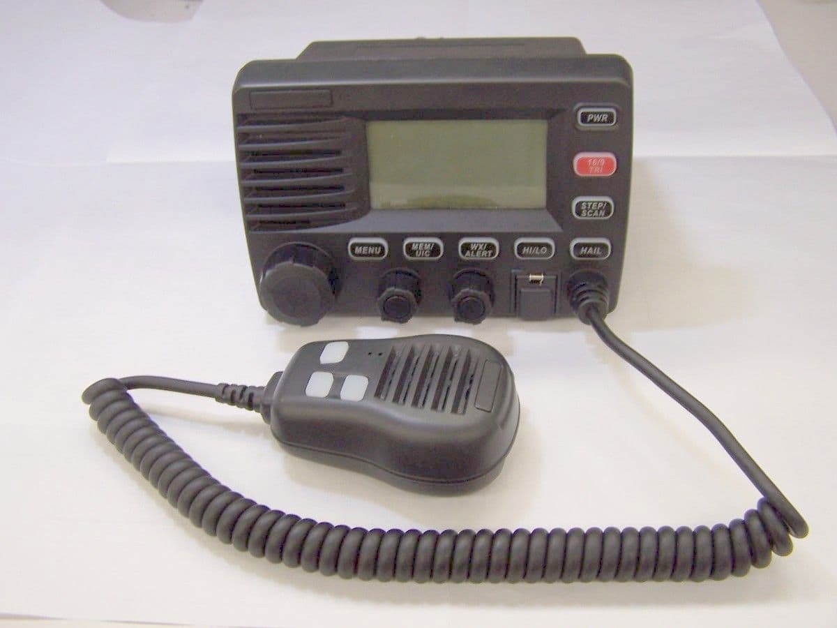
Click to zoom
Application Details
- Equipment Class
- GVH - Part 80 VHF Transmitter (GMDSS)
- Date of Grant
- Feb 07, 2005
- Application Purpose
- Original Equipment
- Date of Application
- Feb 07, 2005
- Equipment Note
- Marine VHF Radio (GMDSS) with Wireless Mircrophone
- Frequency Range
- 156.52500000 - 156.52500000
- Company
- Uniden America Corporation
- Country
- United States
Documents & Files
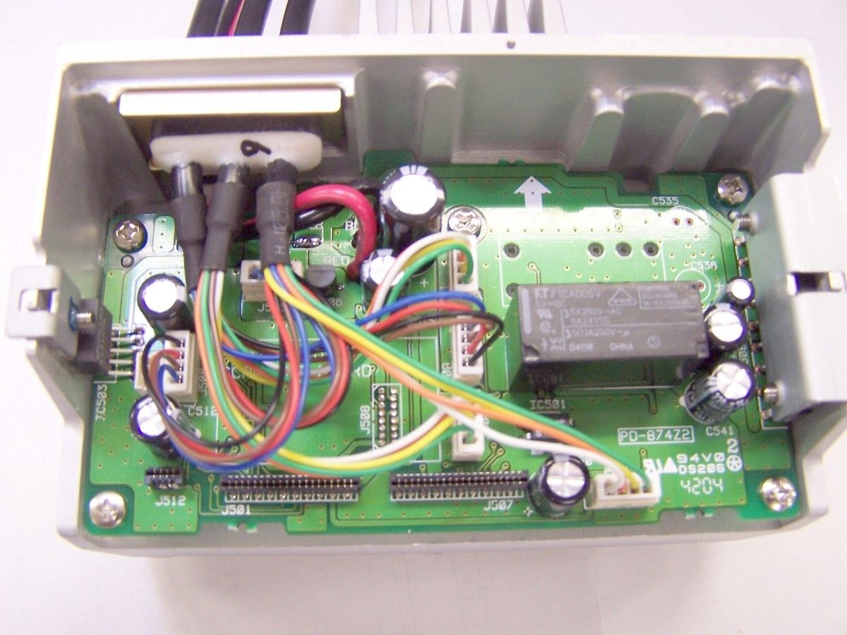
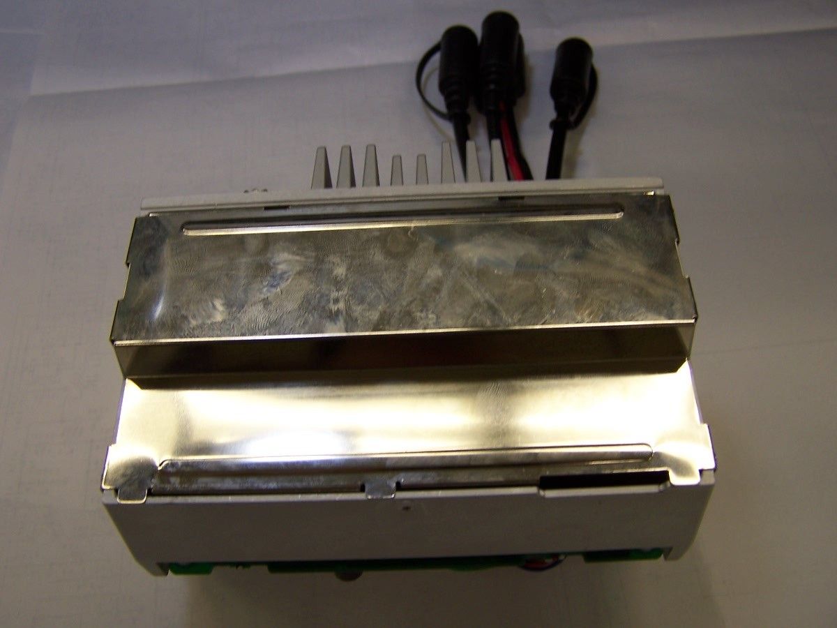
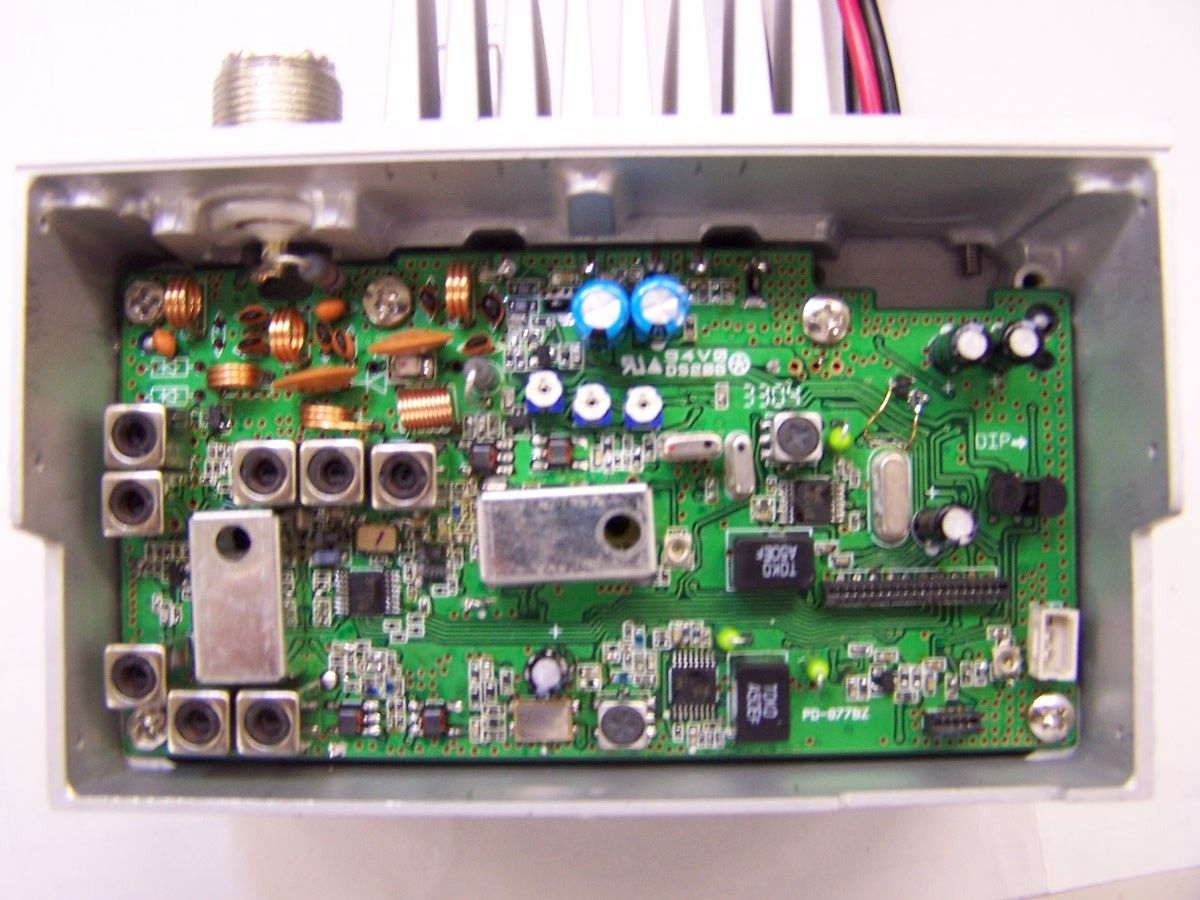
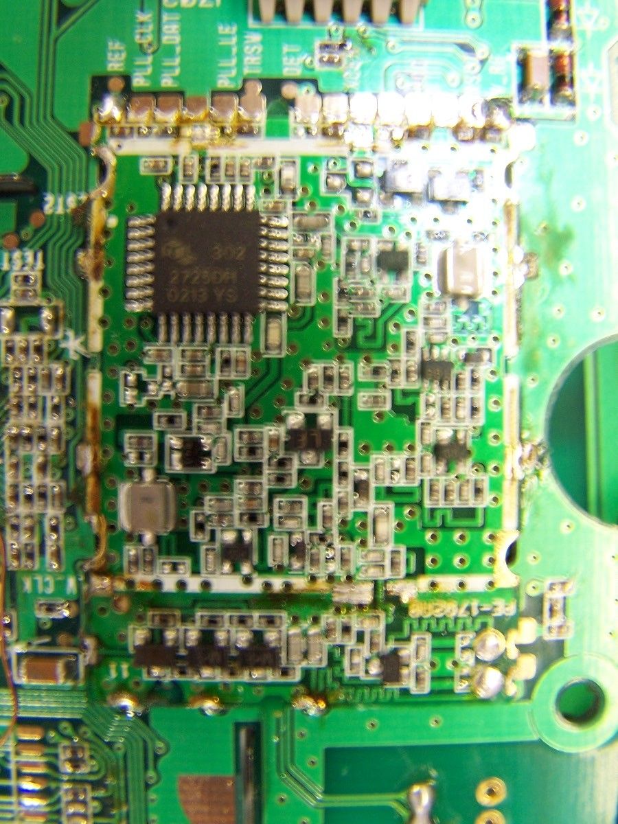
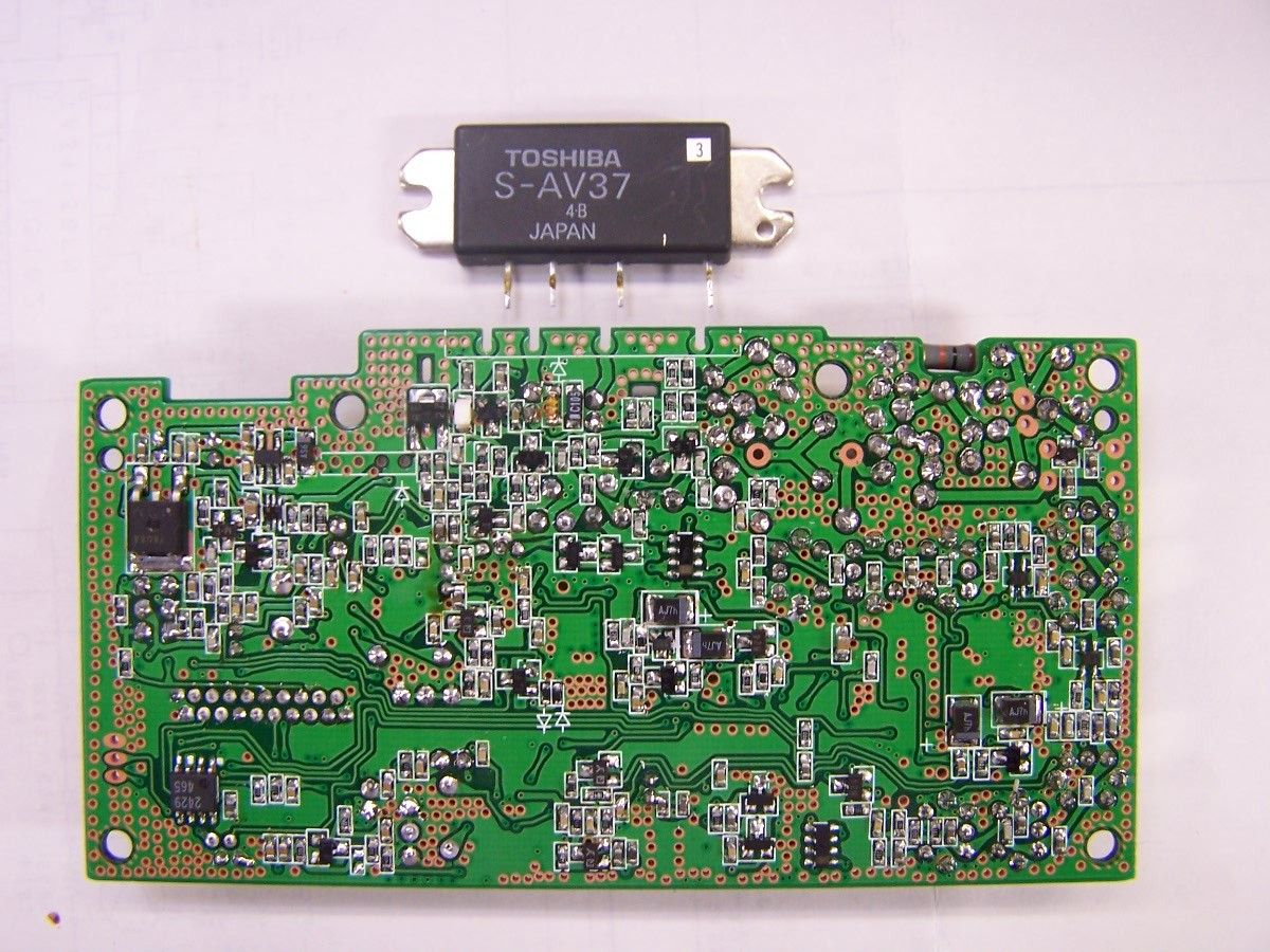
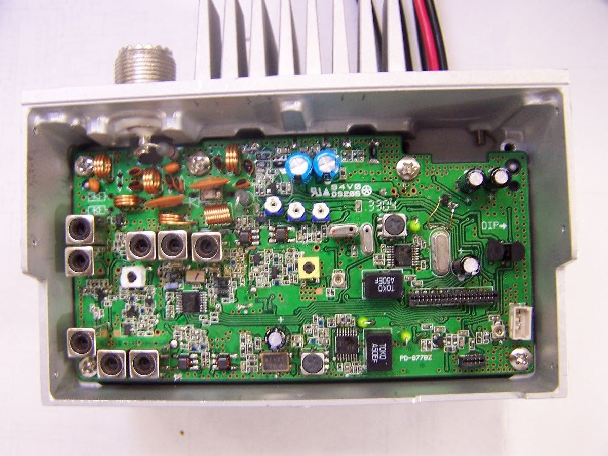
Document Text
Text extracted from the exhibit documents filed with the FCC. Open a document above to read the original.
Users Manual
UM-525 MANUAL OWNER’S Marine Radio Owner’s Manual UM525 Marine Radio UM525 Paper OM.fm Page 1 Tuesday, January 4, 2005 2:54 PM Maritime Radio Services Operation 2 Maritime Radio Services Operation Warning! This transmitter will operate on channels/frequencies that have restricted use in the United States. The channel assignments include frequencies assigned for exclusive use of the U.S. Coast Guard, use in Canada, and use in international waters. Operation on these frequencies without proper authorization is strictly forbidden. For frequencies/channels that are currently for use in the U.S. without an individual license, please contact the FCC Call Center at 1-888-CALL-FCC. For individuals requiring a license, such as commercial users, you should obtain a license application from your nearest FCC field office (for US users) or Industry Canada (for Canadian users). FCC / Industry Canada Information Certification .................................................................... FCC Part 80 or RSS-182/188 Output Power ............................................................ 1 Watt (low) and 25 Watts (high) Emission ....................................................................................... 16K0F3E, 16K0F2D Transmitter Frequency Range ............................................... 156.025 to 157.425 MHz FCC Identifier ........................................................................................... AMWUT601 IC Certification Number ............................................................................ 513C-UT601 This device complies with the GMDSS provisions with Part 80 of the FCC Rules, as well as Part 15 of the FCC Rules. Operation is subject to the condition that this device does not cause harmful interference. Unauthorized changes or modifications to this equipment may void compliance with the FCC Rules. Any change or modification must be approved in writing by Uniden Corporation. Changes or modifications not approved by Uniden could void the user’s authority to operate the equipment. The cords on this product and/or accessories contain lead, a chemical known to the State of California to cause birth defects or other reproductive harm. Wash hands after handling. Uniden works to reduce lead content in our PVC coated cords in our products and accessories. Maritime Radio Services Operation UM525 Paper OM.fm Page 2 Tuesday, January 4, 2005 2:54 PM Contents 3 Contents About Digital Selective Calling ............................................................................. 6 Introduction ............................................................................................................ 7 Feature Highlights ................................................................................................. 8 General Features ............................................................................................... 8 Weather Features ............................................................................................... 9 DSC Features ..................................................................................................... 9 Optional Features ............................................................................................... 9 Understanding Your Radio ..................................................................................11 About This Manual ........................................................................................... 11 How The Radio’s Controls Appear in This Manual ........................................... 11 Included With the Radio .......................................................................................13 Controls and Indicators .......................................................................................14 Front Panel ....................................................................................................... 14 Microphone ....................................................................................................... 14 Rear Panel Connectors .................................................................................... 14 Setting Up the Radio ............................................................................................15 Connecting the Antenna ................................................................................... 15 Connecting Power ............................................................................................ 15 Installation ........................................................................................................ 15 Choosing a Location ................................................................................... 16 Engine Noise Suppression .......................................................................... 16 Installing the Radio ...................................................................................... 17 Using a WHAM Microphone With the Radio .................................................... 17 A Look at the Radio .......................................................................................... 18 A Look at the Microphone ................................................................................ 19 A Look at the Display ....................................................................................... 19 Status Icons ................................................................................................. 19 Status Messages ..........................................................................................20 Basic Operation ....................................................................................................21 Turning the Radio On and Off .......................................................................... 21 Selecting a Channel ......................................................................................... 21 Transmitting and Receiving ...............................................…
Text truncated - open the document above for the full version.
Attestation Statements
January 7, 2005 TIMCO Engineering, Inc. 849 NW State Road 45 P.O. Box 370 Newberry, Florida 32669 Attn: Mr. Bruno Clavier RE: Job 2103JC4 – Your Email dated 12/16/2004 FCC ID: AMWUT601 Dear Mr. Clavier: Please accept this as Uniden’s response to your email of December 16, 2004. In the following pages, I will attempt to provide an acceptable reply to the specific questions. However, allow me to first make a general explanation of the relationship between the Job in question (2103JC4) for our Marine VHF Transceiver, identified as AMWUT601, and the 2.4 GHz DSS Wireless Microphone that is a dedicated component of the Marine VHF Transceiver. For your reference, a 2.4 GHz DSS Wireless Microphone was submitted to TIMCO in November 2004 and was tested under your Job 1917UT4. At the time that I made the submission, I verbally received confirmation from Ms. Sharon Hoffman that it would be possible for TIMCO to investigate the 2.4 GHz DSS Wireless Microphone, also identified as AMWUT601 as a Part 15.247 device, plus investigate as a TCB the combination of the wireless microphone as a component of the marine VHF radio under the rules for a Composite Device. Therefore, the 2.4 GHz DSS Wireless Microphone sample was tested at TIMCO’s facility, and the marine VHF transceiver was tested at Uniden’s FCC Registered Test Site in Japan. Although the above responds to your question in item 4, I felt that this should be explained first. Please let me know if you have any questions or concerns over this point. In the following pages, I will address the remainder of your questions in order of your email. Regards, James R. Haynes Vice President, Engineering and Regulatory Affairs Uniden’s Responses Your Question in the email of 12/16/04 1. RF exposure exhibit part 2.1091: Please provide such exhibit to support required separation distance to satisfy the FCC RF exposure requirements and limits for general population/uncontrolled environment. Uniden’s Response A new Owner’s Manual (Draft) is being submitted to replace the one that was originally submitted with this filing. The text in the following has not changed; however, the page numbers are different. On page 15 of the new Owner’s Manual, there are instructions for connecting the radio to an antenna. In the marine VHF transceiver market, except for portable devices, the radio manufacturer does not supply the antenna, which is the radiating element and the concern of FCC Part 2.1091. However, in the supplied Owner’s Manual on page 15, a separation distance is specified for small and large types of typical marine VHF antennas available for user installations. Basically, the distance for small antennas is “3 feet” and for large antennas, the separation distance is specified as “6 feet”. Please note that the same language is used in a similar marine VHF radio, identified as AMWUT910, that was directly filed to the FCC by Uniden America Corp. in August 2003. The Commission issued the Grant of Equipment Authorization for this device on 9/26/2003. The verbiage can be reviewed in the Owner’s Manual exhibit on page 11/64, which is maintained in the Commission’s database. Your Question 2. RF exposure – User’s manual: All qualified end-users of this device must have the knowledge to control their exposure conditions and/or duration, and the exposure conditions and/or duration of their passengers and bystanders, to comply with the General Population/Uncontrolled MPE limit and requirements. A label, as described in this filing, must be displayed on the device to direct users to specific training information for meeting Occupational Exposure Requirements. Users must be provided with the training information, antenna installation and transmitter operating conditions for satisfying RF exposure compliance. Uniden’s Response Please see the response to your question in item 1. However, the Owner’s Manual on page 15 provides the FCC’s suggested text for alerting users to the health risks associated with excessive radiation generated in marine VHF transmitters and emitted from the antenna. Your Question 3. FYI – The equipment class on form 731 was GVH. It will be changed to TNB for part 80 VHF transceiver. Uniden’s Response The subject Marine VHF Transceiver is being submitted as a compliant GMDSS radio that meets the requirements as mandated in Part 80.1101 in Subpart W of the Commission’s Rules. Therefore, we believe that the Equipment Class should remain “GVH”. However, in checking our original application Form 731, I noticed that the only emission designator filed was 16K0F3E. Please note that we are adding 12K6F2D to cover the emissions when Channel 70 is being used to transmit digital selective calling data. Additionally, an addendum to the Test Report is being filed that shows the bandwidth on emissions when the device is generating radio frequency signals on 156.525 MHz (Channel 70). Finally, please note that the equipment label as required in Part 80.1103(e) attests to the GMDSS compatibility. Your Question 4. Form 731 and Test report: There references to a part 15 device operation in the 2.4GHz. Please explain, as we do not have any information on the low power part 15 device. Uniden’s Response The body text of our letter covers this explanation. However, I will coordinate with TIMCO in the submission of a separate application Form 731 to cover the Part 15 portion of a composite filing. Your Question 5. Part 80.203(b) Frequency programming capability: Please provide an attestation for compliance with this section Uniden’s Response On behalf of grantee, Uniden America Corporation, I personally attest that the requirements mandated in Part 80.203(b) are met in the design and manufacture of the subject radio identified as AMWUT601. Further, the Owners Manual that is provided with each radio being marketed contains verbiage required in FCC Part 15.21 that cautions against unauthorized modifications or changes. Signed: Date: January 6, 2005 : Your Question 6. Part 80.203(c) T…
Text truncated - open the document above for the full version.
Cover Letter(s)
REQUEST FOR CONFIDENTIALITY December 14, 2004 To: Federal Communications Commission Equipment Authorization Branch Laboratory Division Office of Engineering and Technology 7435 Oakland Mills Road Columbia, Maryland 21046 Subject: Data for FCC Certification Applicant: Uniden America Corporation 181 N. Country Club Road, P.O. Box 580 Lake City, South Carolina 29560 James R. Haynes, Vice President, Engineering and Regulatory Affairs TYPE OF EQUIPMENT: Part 80 Marine VHF Ship Station Transceiver FCC IDENTIFIER: AMWUT601 Dear Sir or Madam: Some of the material included in this application contains trade secrets and proprietary information not customarily released to the public. Because public disclosure of the material might be harmful to the applicant and provide unjustified benefits to its competitors, it is requested that the following be withheld from public disclosure: Circuit Description Schematic Diagrams Block Diagrams Trade secrets and proprietary information can be held confidential. Therefore, we wish to invoke the act under the provisions of 47CFR, Sections 0.457(d) and 0.459. Please contact the undersigned if you have any questions or need any further information. Regards, James R. Haynes Vice President, Engineering and Regulatory Affairs
ID Label/Location Info
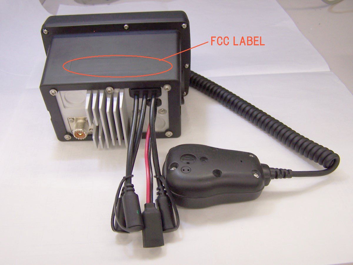
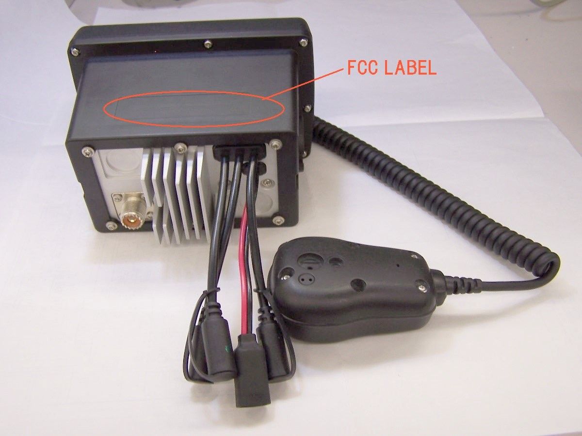
ID Label/Location Info The FCC Label complies with the section 2.925(d) of the FCC Rules and will be permanently affixed to the equipment. Size : 50 mm (W) x 22 mm (H)
Parts List/Tune Up Info
FORM-4 REFERENCE DIAGRAM NO. PAGE MODEL UNIT BLOCKISSUE DATE ISSUED UT601ZH RF2004/11/16KAWAGUCHI TITLEADJUST POINTSUB TITLE REF DIAGRAM *1 TG = TRACKING GENERATOR REV. CODE DATE LOT # / RN # REVISED BY CHECKED BY ENGLISH VERSION95.06 E0132RO (JED-207Z) <E0132.XLS> 28 ALIGNMENT PROCEDURE TP102 TP103 TP401 TP402 L40 5 L411 RT405 RT203RT202 RT101 L109 L114 L102 L101 L106 L104 L105 L119 L120 L121 TP101 FORM-4 REFERENCE DIAGRAM NO. 3-2 PAGE MODEL UNIT BLOCKISSUE DATE ISSUED UT601ZHFRONTFRONT+WHAM RF2004/11/16KWG TITLEFRONTSUB TITLETX REF. DIAGRAM FRONT PCB ADJ. POINT PD-875 TOP VIEW CT95 CLOCK ADJUSTCLOCK ADJUST 12.288MHz ENGLISH VERSION95.06 E0131RO (JED-207Z) <E0132.XLS> ALIGNMENT PROCEDURE Figure:3-2
Test Report
Test Report (VHF marine section) TEST PROCEDURES AND TEST SITE DESCRIPTION FCC ID: AMWUT601 UNI-NO.: UT601ZH MODEL: UM525(XX) Description: VHF MOBILE TYPE MARINE RADIO WITH 2.4GHz LOW POWER COMMUNICATION DEVEICE MEASUREMENT ITEMS Section No. 1. DC Voltage & Current into Final Device 2.1033(C)(8) 2. RF Output Power 2.1046 3. Modulation Characteristics (Audio Roll-off) 2.1047 & 80.213 4. Modulation Characteristics (Audio Frequency Response) 2.1047 5. Modulation Characteristics (Modulation Limiting) 2.1047 6. Occupied Bandwidth 2.1049(c)(1) & 80.211 7. Spurious & Harmonic Emission at Antenna Terminal 2.1051 8. Field Strength of Spurious & Harmonic Radiation 2.1053 9. Frequency Stability (Temperature) 2.1055 & 80.209 10. Frequency Stability (Voltage) 2.1055 & 80.209 11. Receiver radiated spurious emissions 80.217(b) NOTE: List of measurement equipment and test site description are included in this EXHIBIT. 1. DC Voltage & Current into Final Device 2.1033(C)(8) ------------------------------------------ To measure the DC Voltage and Current into Final Amplifying Device, the measuring equipment was connected to the actual P.C.Board of the transmitter. FCC limits: Not specified Test Results: Refer to test data 2. RF Output Power 2.1046 ------------------- The unit was tuned-up in accordance with the alignment procedure stated in the EXHIBIT-6, and was loaded into a 50 ohm resistive termination. The unit was powered through its normally supplied power cable by a DC power supply. Power supply voltage was set to nominal voltage at the power supply terminals with the transmitter off. The unit was operated for three consecutive test cycles of 15 minutes standby and 5 minutes in transmitting. At the end of the third 5 minutes period, the RF output power is measured. During the test, no components of the emission spectrum exceed the limit specified in the applicable rule part for occupied bandwidth or emission limitations. FCC limits: Not specified Test Results: Refer to test data 3. Modulation Characteristics (Audio Roll-off) 2.1047 & 80.213 ----------------------------------------------- To measure the audio roll-off filter response, an audio frequency oscillator and AF VTVM were connected to the actual P.C.Board of the transmitter. AF VTVM and an oscilloscope monitored the output of the audio filter. An AF input level was maintained was maintained constant at least 10 dB below the saturation level at maximum response frequency. The measurement was made under the above conditions by varying the frequency between 1 kHz and 100 kHz. FCC limits: 3 kHz - 15 kHz: -40 log 10 (F/3) dB Above 20kHz : At least -28 dB Test Results: Refer to test data 4. Modulation Characteristics (Audio Frequency Response) 2.1047 --------------------------------------------------------- Operate the unit under the standard test conditions and monitor the output with a modulation or a calibrated test receiver. With a 1000 Hz sine wave (applied through a dummy microphone circuit) used as a 0 dB reference, vary the modulating frequency from 300 to 3000 Hz and observe the level necessary to maintain a constant 30% modulation. FCC limits: 300 - 3000 Hz: 6dB/octave roll-off (+1/-3 dB) Test Results: Refer to test data 5. Modulation Characteristics (Modulation Limiting) 2.1047 ---------------------------------------------------- The transmitter shall be adjusted for full rated system deviation, 1000 Hz and reference it as 0dB input. With modulation frequencies of 300, 1000 and 3000 Hz respectively, vary the audio input to a level 20dB above that required at 100 Hz to produce 60% of rated system deviation. This is required for both up to and down modulation. Record the percent of full system deviation obtained as a function of input level. FCC limits: +/-5 kHz deviation Test Results: Refer to test data 6. Occupied Bandwidth 2.1049(c)(1) & 80.211 ---------------------- The spectrum of the modulated carrier was monitored by a panoramic method capable of 60dB amplitude range. The unit was modulated with a 2500 Hz audio signal at an input level 16dB above that required for 50% of maximum system deviation. In case the 100Hz of CTCSS tone or 100 bps of digital coded data modulation is indicated for this transmitter, a representative measurement data for this operation is also presented. Since the total deviation of the unit is designed as 4.7 kHz Div., the deviation of 2500Hz audio signal was set to 3.7 kHz Div., as the maximum deviation of tone or digital coded signal was continuously set to 1.0 kHz Div. At first, tone or digital signal was disabled and set the 2500 Hz audio signal to 1.85 kHz deviation (= 50% of 3.7 kHz deviation). Then, the input level of 2500Hz audio signal was increased by 16dB. In this condition, the tone or digital coded signal was then enabled and imposed with 2500Hz audio signal. FCC limits: a) -25dB (50 - 100% of assigned frequency) b) -35dB (100 - 250% of assigned frequency) c) 43 + 10log 10 (RF output power in Watts) dB or 80dB, whichever is lesser attenuation for more than 250% of assigned frequency Test Results: Refer to test data 7. Spurious & Harmonic Emission at Antenna Terminal 2.1051 ---------------------------------------------------- Spurious radiation are the radio frequency voltage or power generated within the equipment and appearing at the equipment's output terminals when properly loaded with its characteristic non-radiating load. The unit was modulated with a 2500 Hz tone at an input level 16dB greater than that required 50% modulation. The spectrum was scanned from the lowest frequency generated in the equipment to the tenth harmonic of the carrier. FCC limits: 43 + 10log 10 (RF output power in Watts) dB Test Results: Refer to test data 8. Field Strength of Spurious & Harmonic Radiation 2.1053 --------------------------------------------------- Measurement Procedure & Test Site Description Field strength measurements of radiated spurious emissions were made on a 3-meter range maintained by Uniden C…
Text truncated - open the document above for the full version.
Contact Information
Applicant
Paul Roby
Test Firm
Uniden CorporationKeizo Fujiwara
Technical Specifications
| # | Rule Parts | Frequency Range | Power Output | Emission | Tolerance |
|---|---|---|---|---|---|
| 4 | 80.1101(c)(4) | 156.525 MHz - 156.525 MHz | 1 W | 12K6F2D | 0.0005 % |
Other Applications from Uniden America Corporation
AMWUA2405
Apr 15, 2026RADAR DETECTOR
Equipment Class
JBP - Part 15 Class B Computing Device PeripheralAMWUA2406
Apr 15, 2026RADAR DETECTOR
Equipment Class
JBP - Part 15 Class B Computing Device PeripheralAMWUA2402
Jul 23, 2024RADAR DETECTOR
Equipment Class
CRD - Part 15 Radar Detector
AMWUA2404
Feb 17, 2024Wi-Fi Bluetooth Combo Module
Equipment Class
DTS - Digital Transmission System
AMWUA2301
Feb 15, 2023RADAR DETECTOR
Equipment Class
CRD - Part 15 Radar Detector