AMWUT647Handheld Marine Transceiver
Uniden America Corporation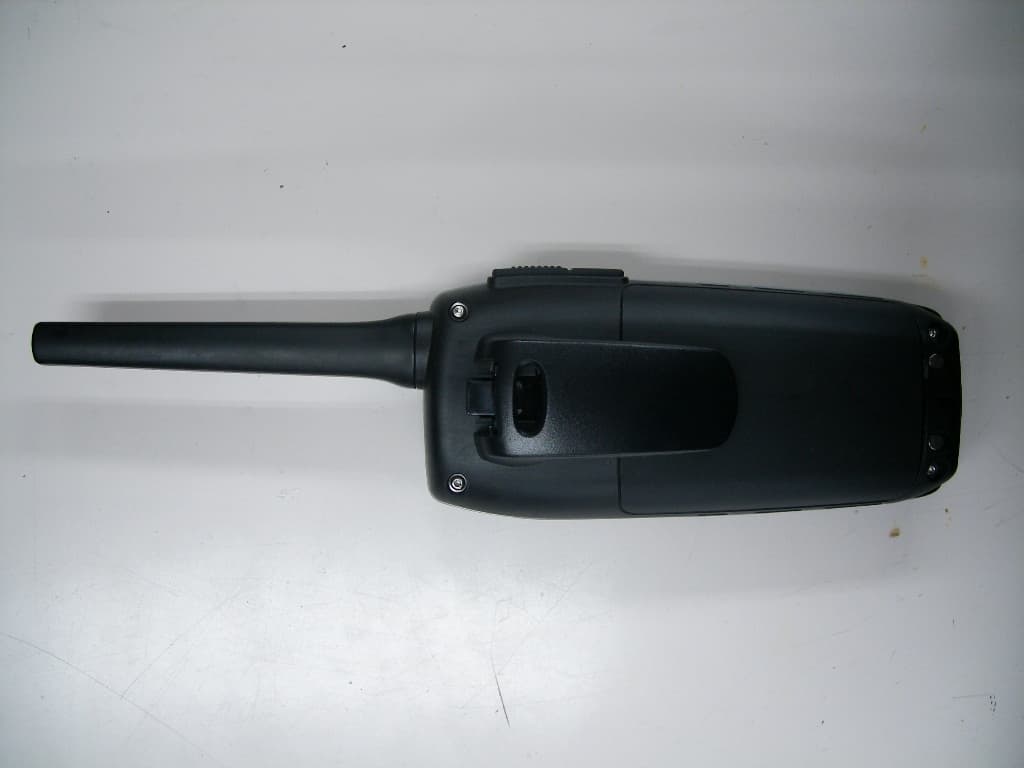
Click to zoom
Application Details
- Equipment Class
- TNF - Licensed Non-Broadcast Transmitter Held to Face
- Date of Grant
- Dec 23, 2013
- Application Purpose
- Original Equipment
- Date of Application
- Dec 23, 2013
- Equipment Note
- Handheld Marine Transceiver
- Frequency Range
- 156.05000000 - 157.42500000
- Company
- Uniden America Corporation
- Country
- United States
Documents & Files
Document Text
Text extracted from the exhibit documents filed with the FCC. Open a document above to read the original.
Users Manual
Atlantis 270 RADIO VHF MARITIME FLOTTANTE GUIDE D’UTILISATION FLOATING VHF MARINE RADIO OWNER’S MANUAL Making a Distress Call For future reference, write your boat’s name & call sign here: Speak slowly - clearly - calmly. 1. Make sure your radio is on. 2. Press the 16/9-TRI key to switch to Channel 16 (156.8 MHz). (If the corner of the display does not show 16, press the 16/9-TRI key again until it does.) 3. Press the Push to Talk key and say: “MAYDAY -- MAYDAY -- MAYDAY.” 4. Say “THIS IS {name of your boat (three times) and call sign/ boat registration number (once)}. ” 5. Repeat “MAYDAY {name of your boat}” once. 6. Tell where you are: (what navigational aids or landmarks are near, or read the latitude and longitude from your GPS). 7. State the nature of your distress (e.g. sinking, medical emergency, man overboard, on fire, adrift, etc.). 8. State the type of assistance you need (medical, towing, pumps, etc.). 9. Give the number of persons aboard and describe the condition of any injured persons. 10. Estimate present seaworthiness of your ship (e.g. how immediate is the danger due to flooding or fire). 11. Briefly describe your ship, giving ship name (i.e., “Blue Duck is 32 foot cabin cruiser, white hull, blue deck house”). 12. Say: “I WILL BE LISTENING ON CHANNEL 16.” 13. End the message by saying “THIS IS {name or call sign of your boat} , OVER.” 14. Release the Push to Talk key and listen. if you do not get an answer after 30 seconds, repeat your call beginning at step 3 above. Faire un appel De Détresse Pour toute référence ultérieure, transcrivez ci-dessous le nom et l’indicatif d’appel de votre bateau: Parlez lentement – clairement – calmement. 1. Vérifiez si votre radio est en marche. 2. Appuyez sur la touche 16/9-TRI du microphone afin de commuter au canal 16 (156,8 MHz). (Si le canal 16 n’apparaît pas à l’affichage, appuyez de nouveau sur la touche 16/9-TRI jusqu’à ce qu’il soit affiché.) 3. Appuyez sur le bouton de microphone Push to Talk et dites:“MAYDAY -- MAYDAY -- MAYDAY”. 4. Donnez l’identité de votre navire en disant : “ICI {nom de votre bateau (trois fois) ou indicatif d’appel et le numéro d’identification de votre bateau (une fois)}”. 5. Dites “MAYDAY {nom ou indicatif d’appel de votre bateau} une fois”. 6. Donnez votre position : (quels sont les points de repère ou aides à la navigation près de vous ou lisez les coordonnées de longitude et de latitude apparaissant sur votre dispositif GPS). 7. Révélez la nature de votre détresse (par exemple, nous sommes en train de couler, urgence médicale, un homme à la mer, un incendie, nous sommes à la dérive, etc. 8. Révélez la nature de l’aide désirée (médicale, remorquage, essence, etc.) 9. Donnez le nombre de personnes à bord et les conditions des blessés, s’il y en a. 10. Donnez la condition de navigabilité actuelle de votre navire, tel que le degré de l’urgence par rapport une inondation, et une incendie. 11. Donnez une brève description de votre navire en donnant le nom du bateau (par exemple, “Blue Duck est un yacht de croisière de 32 pieds, avec une coque blanche et un rouffle bleu.). 12. Dites : “JE VAIS ÉCOUTER SUR LE CANAL 16”. 13. Terminez le message en disant “ICI {nom ou indicatif d’appel de votre bateau}, À VOUS”. 14. Relâchez le bouton Push to Talk du microphone et écoutez. si vous n’obtenez pas de réponse après 30 secondes, répétez l’appel encommençant à l’étape 3 ci-dessus. table of Contents Introduction.................................E-1 Features.......................................E-1 Getting.Started............................E-3 What’s.included............................E-3 Parts.of.the.Atlantis.270:...............E-4 Front.view....................................E-4 Back.view....................................E-4 Charger.......................................E-5 Reading.the.display......................E-6 Display.icons.and.. what.they.mean.......................E-6 How.It.Works...............................E-7 Normal.mode.operation................E-8 Normal.mode.with.. Weather.Alert.Watch...............E-8 Normal.mode.with.Triple.. Watch.or.Dual.Watch..............E-9 Scan.mode.operation...................E-9 Using.the.radio.in.scan.mode...... E-9 Scan.mode.with.Weather.Alert. Watch....................................E-10 Scan.mode.with.Triple.. Watch.or.Dual.Watch............E-10 Weather.mode.............................E-11 Using.the.radio.in.. weather.mode........................E-11 Weather.mode.with.. Weather.Alert.Watch..............E-11 Weather.mode.with.. Triple.Watch.or.Dual.Watch..E-12 Setting.Up.the.Hardware.......... E-12 Install.the.Battery.Pack...............E-12 Mounting.the.Charger.................E-13 Charging.the.Battery...................E-13 Important.notes.on.. charging.the.battery..............E-13 Attaching.the.Belt.Clip................E-14 Using.Your.Radio......................E-15 Changing.the.Volume.................E-15 Setting.the.Squelch.Level...........E-15 Changing.the.Channel................E-16 Making.a.Transmission...............E-16 Boosting.the.transmission.. power....................................E-16 Setting.Key.Lock.........................E-17 Setting.the.UIC.Channel.. Mode........................................E-17 Turning.the.Key.Beep.On.. and.Off.....................................E-17 Saving.a.Channel.to.. Memory....................................E-17 Scanning.Channels.in.. Memory....................................E-17 Battery.Save.Feature..................E-18 Maintenance.and. Troubleshooting.....................E-18 Common.Questions....................E-18 Specifications...........................E-20 Channels.and.Frequencies.. (MHz).......................................E-21 US.channel.frequencies.and. names...................................E-21 Canadian.channel.frequencies.. and.names............................E-23 International.channel.. frequencies.and.names.........E-25 Weather.channel.frequencies.. and.names............................E-27 …
Text truncated - open the document above for the full version.
External Photos
External Photos Front View Rear View External Photos Rear View, Battery Cover opened Front Left External Photos Front Right Charger Top External Photos Charger Front Charger Rear
Internal Photos
Internal Photos Case Opened, PCB Top PCB Top and antenna detached Internal Photos PCB bottom PCB bottom without Shield Internal Photos Charger Case Opened, PCB Bottom Charger PCB Top
RF Exposure Info
Applicant: Uniden America Corporation FCC ID: AMWUT647 IC: 513C-UT647 Model(s): Atlantis 270 DUT Type: Portable VHF PTT Marine Radio Transceiver 156.025-157.425 MHz 2013 Celltech Labs Inc. This document is not to be reproduced in whole or in part without the prior written permission of Celltech Labs Inc. Page 1 of 31 Date(s) of Evaluation Nov 27 & 28, 2013 Test Report Serial No. 111813AMW-1269 Test Report Revision No. Rev. 1.0 (1st Release) Test Report Issue Date December 9, 2013 Description of Test(s) Specific Absorption Rate RF Exposure Category Gen. Pop. / Uncontrolled Test Lab Certificate No. 2470.01 DECLARATION OF COMPLIANCE SAR RF EXPOSURE EVALUATION FCC & IC Name CELLTECH LABS INC. Test Lab Information Address 21-364 Lougheed Road, Kelowna, B.C. V1X 7R8 Canada Test Lab Accreditation(s) A2LA ISO/IEC 17025:2005 (A2LA Test Lab Certificate No. 2470.01) Name UNIDEN AMERICA CORPORATION Applicant Information Address 4700 Amon Carter Boulevard, Fort Worth, Texas 76155 United States Application Type(s) FCC TCB Certification IC CB Certification Standard(s) Applied FCC 47 CFR §2.1093 IC Health Canada Safety Code 6 FCC KDB 447498 D01v05r01 FCC KDB 643646 D01v01r01 FCC KDB 865664 D02v01r01 FCC KDB 865664 D01v01r02 IC RSS-102 Issue 4 Procedure(s) Applied IEEE 1528-2013 IEC 62209-1:2005, 62209-2:2010 FCC Licensed Non-Broadcast Transmitter Held to Face (TNF) Device Classification(s) IC Maritime Radio Transmitter and Receiver (RSS-182) Device RF Exposure Category FCC/IC General Population / Uncontrolled Environment FCC ID: AMWUT647 Device Identifier(s) IC: 513C-UT647 Device Model(s) Model(s) Atlantis 270 Test Sample Serial No. None (Identical Prototype) Date of Sample Receipt November 18, 2013 Date(s) of Evaluations November 27 & 28, 2013 Test Sample Hardware Rev. No. n/a Test Sample Firmware Rev. No. n/a Device-Under-Test Description (DUT) Portable FM VHF Push-To-Talk (PTT) Marine Radio Transceiver VHF Transmit Frequency Range(s) 156.025 - 157.425 MHz (VHF Marine Band) Manuf. Rated Output Power 5.7 Watts Conducted +0.25 W / -0.35 W Hi Power (Boost mode) Measured RF Output Power 5.54 Watts 37.4 dBm Conducted 156.8 MHz (Ch. 16) Battery Type Tested Li-ion Polymer 7.4 V 1100 mAh P/N: BT-1035 Antenna Type Tested Stub (Non-detachable) P/N: n/a Body-worn Accessory Tested Belt-Clip is for carrying purposes only Face-held (FCC) 0.152 W/kg 1g 50% PTT duty factor Max. SAR Level(s) Evaluated Face-held (IC) 0.159 W/kg 1g 50% PTT duty factor FCC/IC Spatial Peak SAR Limit HEAD 1.6 W/kg 1g 50% PTT duty factor General Population / Uncontrolled Celltech Labs Inc. declares under its sole responsibility that this wireless portable device has demonstrated compliance with the Specific Absorption Rate (SAR) RF exposure requirements specified in FCC 47 CFR §2.1093 and Health Canada Safety Code 6 for the General Population / Uncontrolled Exposure environment. The device was tested in accordance with the measurement procedures specified in KDB 447498, Industry Canada RSS-102 Issue 4, IEEE Standard 1528-2013 and IEC International Standard 62209-2:2010. All measurements were performed in accordance with the SAR system manufacturer recommendations. I attest to the accuracy of data. All measurements were performed by me or were made under my supervision and are correct to the best of my knowledge and belief. I assume full responsibility for the completeness of these measurements and vouch for the qualifications of all persons taking them. The results and statements contained in this report pertain only to the device(s) evaluated. This test report shall not be reproduced partially, or in full, without the prior written approval of Celltech Labs Inc. Test Report Approved By Art Voss Engineering Technologist Celltech Labs Inc. Applicant: Uniden America Corporation FCC ID: AMWUT647 IC: 513C-UT647 Model(s): Atlantis 270 DUT Type: Portable VHF PTT Marine Radio Transceiver 156.025-157.425 MHz 2013 Celltech Labs Inc. This document is not to be reproduced in whole or in part without the prior written permission of Celltech Labs Inc. Page 2 of 31 Date(s) of Evaluation Nov 27 & 28, 2013 Test Report Serial No. 111813AMW-1269 Test Report Revision No. Rev. 1.0 (1st Release) Test Report Issue Date December 9, 2013 Description of Test(s) Specific Absorption Rate RF Exposure Category Gen. Pop. / Uncontrolled Test Lab Certificate No. 2470.01 TABLE OF CONTENTS 1.0 INTRODUCTION _____________________________________________ 4 2.0 SAR MEASUREMENT SYSTEM _________________________________ 4 3.0 RF CONDUCTED OUTPUT POWER MEASUREMENT _______________ 5 4.0 NO. OF TEST CHANNELS (N C ) _________________________________ 5 5.0 SAR PROBE CALIBRATION & MEASUREMENT FREQUENCIES__________________________________________________ 5 6.0 FLUID DIELECTRIC PARAMETERS _____________________________ 6 7.0 SAR MEASUREMENT SUMMARY _______________________________ 7 8.0 SAR SCALING (MANUFACTURER TOLERANCE) __________________ 7 9.0 DETAILS OF SAR EVALUATION ________________________________ 8 10.0 SAR EVALUATION PROCEDURES _____________________________ 8 11.0 SYSTEM PERFORMANCE CHECK _____________________________ 9 12.0 SIMULATED EQUIVALENT TISSUES __________________________ 10 13.0 SAR LIMITS _______________________________________________ 10 14.0 ROBOT SYSTEM SPECIFICATIONS ___________________________ 11 15.0 PROBE SPECIFICATION (ET3DV6) ____________________________ 11 16.0 BARSKI PLANAR PHANTOM_________________________________ 11 17.0 DEVICE HOLDER __________________________________________ 11 18.0 TEST EQUIPMENT LIST _____________________________________ 11 19.0 MEASUREMENT UNCERTAINTIES (IC ONLY) ___________________ 11 20.0 REFERENCES _____________________________________________ 11 APPENDIX A - SAR MEASUREMENT PLOTS ________________________ 11 APPENDIX B - SYSTEM PERFORMANCE CHECK PLOTS______________ 11 APPENDIX C - MEASURED FLUID DIELECTRIC PARAMETERS ________ 11 APPENDIX D - SAR TEST SETUP & DUT PHOTOGRAPHS _____________ 11 APPENDIX E - DIPOLE CALIBRATION ____________…
Text truncated - open the document above for the full version.
Test Report
FCC PART 80 AND IC RSS-182 (i5) TEST REPORT APPLICANT UNIDEN AMERICA CORPORATION 6225 N. State Highway 161, Suite 300 IRVING TEXAS 75038 USA FCC ID AMWUT647 IC CERTIFICATION 513C-UT647 MODEL NUMBER ATLANTIS 270, VHF75 PRODUCT DESCRIPTION HANDHELD MARINE TRANSCEIVER DATE SAMPLE RECEIVED 10/29/2013 DATE TESTED 11/4/2013 TESTED BY JOE SCOGLIO APPROVED BY JOE SCOGLIO TIMCO REPORT NO. 1828AUT13TestReport.docx TEST RESULTS PASS FAIL THE ATTACHED REPORT SHALL NOT BE REPRODUCED EXCEPT IN FULL WITHOUT THE WRITTEN APPROVAL OF TIMCO ENGINEERING, INC. Testing Certificate 0955-01 849 NW STATE ROAD 45 NEWBERRY, FL 32669 USA PH: 888.472.2424 OR 352.472.5500 FAX: 352.472.2030 EMAIL: [email protected] HTTP://WWW.TIMCOENGR.COM Applicant: UNIDEN AMERICA CORPORATION FCC ID: AMWUT647 IC CERT #: 513C-UT647 Report: U\UNIDEN AMW\1828AUT13\1828AUT13TestReport.docx Page 2 of 21 TABLE OF CONTENTS GENERAL REMARKS ........................................................................................................... 3 GENERAL INFORMATION .................................................................................................... 4 TEST PROCEDURES ............................................................................................................ 5 TECHNICAL DATA ............................................................................................................... 6 RF POWER OUTPUT ............................................................................................................ 7 MODULATION CHARACTERISTICS ...................................................................................... 8 AUDIO FREQUENCY RESPONSE ......................................................................................... 9 AUDIO LOW PASS FILTER ................................................................................................. 10 AUDIO INPUT VERSUS MODULATION ............................................................................... 11 OCCUPIED BANDWIDTH ................................................................................................... 12 SPURIOUS EMISSIONS AT ANTENNA TERMINALS (CONDUCTED) .................................... 14 FIELD STRENGTH OF SPURIOUS EMISSIONS .................................................................. 16 FREQUENCY STABILITY .................................................................................................... 18 EMC EQUIPMENT LIST ...................................................................................................... 19 EXTERNAL PHOTOS OF DUT ............................................................................................ 21 Applicant: UNIDEN AMERICA CORPORATION FCC ID: AMWUT647 IC CERT #: 513C-UT647 Report: U\UNIDEN AMW\1828AUT13\1828AUT13TestReport.docx Page 3 of 21 GENERAL REMARKS The attached report shall not be reproduced except in full without the written permission of Timco Engineering Inc. The test results relate only to the items tested. Summary The device under test does: fulfill the general approval requirements as identified in this test report not fulfill the general approval requirements as identified in this test report Attestations This equipment has been tested in accordance with the standards identified in this test report. To the best of my knowledge and belief, these tests were performed using the measurement procedures described in this report. All instrumentation and accessories used to test products for compliance to the indicated standards are calibrated regularly in accordance with ISO 17025: 2005 requirements. Testing Certificate # 0955-01 I attest that the necessary measurements were made, under my supervision, at: Timco Engineering Inc. 849 NW State Road 45 Newberry, Fl 32669 Authorized Signatory Name: Joe Scoglio Engineering Project Manager Date: 11/4/2013 Applicant: UNIDEN AMERICA CORPORATION FCC ID: AMWUT647 IC CERT #: 513C-UT647 Report: U\UNIDEN AMW\1828AUT13\1828AUT13TestReport.docx Page 4 of 21 GENERAL INFORMATION DUT Specification DUT Description HANDHELD MARINE TRANSCEIVER FCC ID AMWUT647 IC Certification 513C-UT647 Model Number ATLANTIS 270, VHF75 Operating Frequency 156.025-157.425 MHz Test Frequencies 156.050 MHz and 157.425 MHz Type of Emission 16K0G3E, 16KOF3E Modulation FM DUT Power Source 110–120Vac/50– 60Hz DC Power Battery Operated Exclusively Test Item Prototype Pre-Production Production Type of Equipment Fixed Mobile Portable Antenna Connector Fixed antenna Test Conditions The temperature was 26ºC Relative humidity of 50%. Modification to the DUT None Test Exercise The DUT was placed in continuous transmit mode. Applicable Standards ANSI/TIA 603-C:2004, FCC CFR 47 Part 80, IC RSS- 182 (issue 5) and RSS-GEN (issue 3) Test Facility Timco Engineering Inc. at 849 NW State Road 45 Newberry, FL 32669 USA. Applicant: UNIDEN AMERICA CORPORATION FCC ID: AMWUT647 IC CERT #: 513C-UT647 Report: U\UNIDEN AMW\1828AUT13\1828AUT13TestReport.docx Page 5 of 21 TEST PROCEDURES Power Line Conducted Interference: The procedure used was ANSI/TIA 603-C: 2004 using a 50uH LISN. Both lines were observed with the DUT transmitting. The bandwidth of the spectrum analyzer was 10 kHz with an appropriate sweep speed. Bandwidth 20 dB: The measurements were made with the spectrum analyzer's resolution bandwidth (RBW) = 1 MHz and the video bandwidth (VBW) = 3 MHz and the span set as shown on plot. Power Output: The RF power output was measured at the antenna feed point using a peak power meter. Antenna Conducted Emissions: The RBW = 100 kHz, VBW = 300 kHz and the span set to 10.0 MHz and the spectrum was scanned from 30 MHz to the 10 th harmonic of the fundamental. Above 1 GHz the resolution bandwidth was 1 MHz and the VBW = 3 MHz and the span to 50 MHz. Radiation Interference: The test procedure used was ANSI C63.4-2004 using an Agilent spectrum receiver with pre-selector. The bandwidth (RBW) of the spectrum receiver was 100 kHz up to 1 GHz and 1 MHz above 1 GHz with an ap…
Text truncated - open the document above for the full version.
Contact Information
Applicant
Paul Roby
Test Firm
Timco Engineering, Inc.Bruno Clavier
Technical Specifications
| # | Rule Parts | Frequency Range | Power Output | Emission | Tolerance |
|---|---|---|---|---|---|
| 4 | 8 | 156.05 MHz - 157.425 MHz | 1 W | 16K0F3E | 7.63 ppm |
Other Applications from Uniden America Corporation
AMWUA2405
Apr 15, 2026RADAR DETECTOR
Equipment Class
JBP - Part 15 Class B Computing Device PeripheralAMWUA2406
Apr 15, 2026RADAR DETECTOR
Equipment Class
JBP - Part 15 Class B Computing Device PeripheralAMWUA2402
Jul 23, 2024RADAR DETECTOR
Equipment Class
CRD - Part 15 Radar Detector
AMWUA2404
Feb 17, 2024Wi-Fi Bluetooth Combo Module
Equipment Class
DTS - Digital Transmission System
AMWUA2301
Feb 15, 2023RADAR DETECTOR
Equipment Class
CRD - Part 15 Radar Detector