AMWUT650VHF/GMRS/FRS Marine Radio - Portable
Uniden America Corporation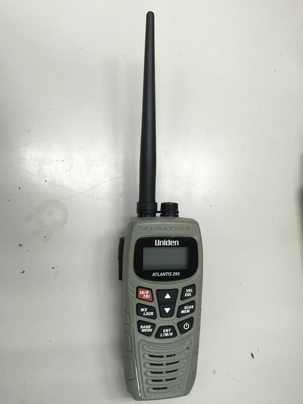
Click to zoom
Application Details
- Equipment Class
- FRF - Part 95 Family Radio Face Held Transmitter
- Date of Grant
- Dec 22, 2014
- Application Purpose
- Original Equipment
- Date of Application
- Dec 22, 2014
- Equipment Note
- VHF/GMRS/FRS Marine Radio - Portable
- Frequency Range
- 462.56250000 - 467.71250000
- Company
- Uniden America Corporation
- Country
- United States
Documents & Files
Document Text
Text extracted from the exhibit documents filed with the FCC. Open a document above to read the original.
Users Manual
ATLANTIS 290/294 ADDENDUM December 2014 FCC RF EXPOSURE INFORMATION In August 1996 the Federal Communications Commission (FCC) of the United States with its action in Report and Order FCC 96-326 adopted an updated safety standard for human exposure to radio frequency electromagnetic energy emitted by FCC regulated transmitters. Those guidelines are consistent with the safety standard previously set by both U.S. and international standards bodies. The design of the radio complies with the FCC guidelines and these international standards. This device complies with the SAR RF safety requirement when a 50% duty cycle (50% talk time) is observed. Never allow children to operate the radio without adult supervision and the knowledge of the following guidelines. WARNING! It is up to the user to properly operate this radio Do not use the radio with a damaged antenna. If a damaged antenna contacts the skin, a minor burn may result.
Users Manual
Atlantis 290 Atlantis 295 Radio VHF maritime à double bande + radio GMRS GUIDE D’UTILISATION Dual Band (GMRS + Marine VHF) Radio OWNER’S MANUAL Atlantis 290 Atlantis 295 MAKING A MARINE DISTRESS CALL For future reference, write your boat’s name & call sign here: Speak slowly - clearly - calmly. 1. Make sure your radio is on. 2. Press the 16/9-TRI key to switch to Channel 16 (156.8 MHz). (If the display does not show 16, press the 16/9-TRI key again until it does.) 3. Change the power level to HIGH. 4. Press the Push-to-Talk key (PTT) and say: “MAYDAY -- MAYDAY -- MAYDAY.” 5. Say “THIS IS {name of your boat (three times) and call sign/ boat registration number (once)}.” 6. Repeat “MAYDAY {name of your boat}” once. 7. Tell where you are: (what navigational aids or landmarks are near, or read the latitude and longitude from your GPS). 8. State the nature of your distress (e.g. sinking, medical emergency, man overboard, on fire, adrift, etc.). 9. State the type of assistance you need (medical, towing, pumps, etc.). 10. Give the number of persons aboard and describe the condition of any injured persons. 11. Estimate present seaworthiness of your ship (e.g. how immediate is the danger due to flooding or fire). 12. Briefly describe your ship, giving ship name (i.e., “Blue Duck is 32 foot cabin cruiser, white hull, blue deck house”). 13. Say: “I WILL BE LISTENING ON CHANNEL 16.” 14. End the message by saying “THIS IS {name or call sign of your boat}, OVER.” 15. Release PTT and listen. If you do not get an answer after 30 seconds, repeat your call beginning at step 3 above. FAIRE UN APPEL MARITIME DE DÉTRESSE Pour toute référence ultérieure, transcrivez ci-dessous le nom et l’indicatif d’appel de votre bateau: Parlez lentement – clairement – calmement. 1. Vérifiez si votre radio est en marche. 2. Appuyez sur la touche 16/9 TRI du microphone afin de commuter au canal 16 (156,8 MHz). (Si le canal 16 n’apparaît pas à l’affichage, appuyez de nouveau sur la touche 16/9 TRI jusqu’à ce qu’il soit affiché.) 3. Changez le niveau d’alimentation au niveau élevé “HIGH”. 4. Appuyez sur le bouton de microphone Push-to-Talk et dites:“MAYDAY -- MAYDAY -- MAYDAY”. 5. Donnez l’identité de votre navire en disant : “ICI {nom de votre bateau (trois fois) ou indicatif d’appel et le numéro d’identification de votre bateau (une fois)}”. 6. Dites “MAYDAY {nom ou indicatif d’appel de votre bateau} une fois”. 7. Donnez votre position : (quels sont les points de repère ou aides à la navigation près de vous ou lisez les coordonnées de longitude et de latitude apparaissant sur votre dispositif GPS). 8. Révélez la nature de votre détresse (par exemple, nous sommes en train de couler, urgence médicale, un homme à la mer, un incendie, nous sommes à la dérive, etc. 9. Révélez la nature de l’aide désirée (médicale, remorquage, essence, etc.) 10. Donnez le nombre de personnes à bord et les conditions des blessés, s’il y en a. 11. Donnez la condition de navigabilité actuelle de votre navire, tel que le degré de l’urgence par rapport une inondation, et une incendie. 12. Donnez une brève description de votre navire en donnant le nom du bateau (par exemple, “Blue Duck est un yacht de croisière de 32 pieds, avec une coque blanche et un rouffle bleu.). 13. Dites : “JE VAIS ÉCOUTER SUR LE CANAL 16”. 14. Terminez le message en disant “ICI {nom ou indicatif d’appel de votre bateau}, À VOUS”. 15. Relâchez le bouton Push-to-Talk du microphone et écoutez. Si vous n’obtenez pas de réponse après 30 secondes, répétez l’appel encommençant à l’étape 3 ci-dessus. Table of Contents MANUAL CONVENTIONS ................E-1 INTRODUCTION .................E-2 MARINE (VHF) MODE FEATURES .....................E-2 WEATHER (WX) MODE FEATURES .....................E-2 GMRS/FRS MODE FEATURES .....................E-2 GMRS Licensing Requirement ................E-3 COMMON FEATURES ......E-3 WATERPROOF SPECIFICATIONS...........E-4 GETTING STARTED ...........E-5 WHAT’S INCLUDED .........E-5 PARTS OF THE ATLANTIS 290/295 .........E-5 Front view .......................E-5 Back ...............................E-7 Charger ..........................E-7 READING THE DISPLAY ..E-8 Display icons and what they mean ...........E-8 HARDWARE SETUP ..........E-9 INSTALL THE BATTERY ..E-9 INSTALL ALKALINE BATTERIES .................E-10 MOUNT THE CHARGER ....................E-10 CHARGE THE BATTERY ......................E-11 INSTALL/REMOVE THE BELT CLIP ....................E-11 INSTALL OPTIONAL EXTERNAL SPEAKER/ MICROPHONE ..............E-12 ATLANTIS 290/295 OPERATION ...................E-12 COMMON OPERATIONS ...............E-12 Power On/Off ................E-12 Change the Volume .....E-12 Set the Squelch Level ..E-12 Set Key Lock ................E-13 Select Band Type .........E-13 Change the Channel ....E-13 Make a Transmission ...E-13 Save a Channel to Memory .....................E-14 Scan Channels in Memory ......................E-14 MENUS ............................E-14 OPERATION MODES ......E-16 Normal Mode Operation ..................E-17 Scan Mode Operation ...................E-18 Weather Watch Modes ........................E-19 MAINTENANCE / TROUBLESHOOTING ...E-23 COMMON QUESTIONS ..E-23 E-1 Uniden Atlantis 290/295 Radio Owner’s Manual See the inside front cover for instructions on making a Marine distress call! MANUAL CONVENTIONS This Owner’s Guide provides operations for both the Atlantis 290 and Atlantis 295 radios. These operations are identical between the two models. The two models are treated as a single entity and are described in single tense (for example, “the radio provides” instead of ‘the radios provide”) except where differences are specifically noted. Throughout this manual, “Atlantis 290/295” indicates both the Atlantis 290 and the Atlantis 295 radios. SPECIFICATIONS .............E-25 CHANNELS AND FREQUENCIES (MHZ) ............................E-26 US channel frequencies and names .................E-26 Canadian channel frequencies and names .................E-2…
Text truncated - open the document above for the full version.
Cover Letter(s)
Uniden America Corporation 3001 Gateway Drive, Suite 130 Irving, TX 75063 817-858-3300 Fax: 817-858-3333 12/12/2014 Federal Communications Commission Authorization and Evaluation Division 1435 Oakland Mills Road Columbia, MD 21046 United States of America Subject: Confidentiality Request regarding application for certification of FCC ID: AMWUT650 Applicant: Uniden America Corporation 3001 Gateway Drive, Suite 130 Irving, TX 75063 To Whom It May Concern: Pursuant to Sections 0.457 and 0.459 of the Commission's Rules, we hereby request confidential treatment of information accompanying this application as outlined below: Exhibit Type File Name Tuning Procedure AMWUT650_TUNING _PROCEDURE.pdf Operational Description AMWUT650_CIRCUIT_DESCRIPTION.pdf Block Diagram AMWUT650_BLOCK DIAGRAM.pdf Schematics AMWUT650_CIRCUIT DIAGRAM.pdf The above materials contain trade secrets and proprietary information not customarily released to the public. The public disclosure of these materials may be harmful to our company and provide unjustified benefits to our competitors. Sincerely, Renji Inuzuka Director, Engineering and Quality Uniden America Corporation
Cover Letter(s)
Uniden America Corporation 3001 Gateway Drive, Suite 130 Irving, TX 75063 817-858-3300 Fax: 817-858-3333 12/15/2014 Federal Communications Commission Equipment Authorization Branch 7435 Oakland Mills Road Columbia, MD 21046 To whom it may concern: We, Uniden America Corporation, hereby authorize Ben Hewson of Celltech Labs Inc. to act on our behalf in all matters relating to applications for equipment authorization, including the signing of all documents relating to these matters. Any and all acts carried out by Ben Hewson of Celltech Labs Inc. on our behalf shall have the same effect as acts of our own. We also hereby certify that no party to this application is subject to a denial of benefits, including FCC benefits, pursuant to Section 5301 of the Anti-Drug Abuse Act of 1988, 21 U.S. C. 853(a). Sincerely, Renji Inuzuka Director, Engineering and Quality Uniden America Corporation
ID Label/Location Info
Label Location Information Battery compartment on back Model Name, FCC ID, IC Number and Serial Number
Parts List/Tune Up Info
INQUIRY BOM BY MODEL or LOT MODELUT650ZV TOTAL457 ASSY CODEPARTS CODEDESCRIPTIONSPECREF NOQTY AT650ZVBAEBPDG1025AA1PCB:MAINPD-1025AA 1/3B1011 AT650ZVBAEBPDG1025AA2PCB:SWITCHPD-1025AA 2/3B1021 AT650ZVBAEBCNA812204GC:CERAMIC M/L (1005) TAPE22PF 50V J CHC1011 AT650ZVBAEBCNA812204GC:CERAMIC M/L (1005) TAPE22PF 50V J CHC1021 AT650ZVBAEBCNA818092GC:CERAMIC M/L (1005) TAPE8PF 50V D CHC1031 AT650ZVBAEBCNA816804GC:CERAMIC M/L (1005) TAPE68PF 50V J CHC1041 AT650ZVBAEBCNA814704GC:CERAMIC M/L (1005) TAPE47PF 50V J CHC1051 AT650ZVBAEBCNB111045GC:CERAMIC M/L (1005) TAPE0.1u 10V K BC1061 AT650ZVBAEBCNB811025GC:CERAMIC M/L (1005) TAPE0.001u 50V K BC1071 AT650ZVBAEBCNB111045GC:CERAMIC M/L (1005) TAPE0.1u 10V K BC1081 AT650ZVBAEBCNB811025GC:CERAMIC M/L (1005) TAPE0.001u 50V K BC1091 AT650ZVBAEBCNB813315GC:CERAMIC M/L (1005) TAPE330p 50V K BC1101 AT650ZVBAEBCNB901055GC:CERAMIC M/L (1005) TAPE1UF 6.3V K BC1111 AT650ZVBAEBCNA818092GC:CERAMIC M/L (1005) TAPE8PF 50V D CHC1121 AT650ZVBAEBCNA811002GC:CERAMIC M/L (1005) TAPE10PF 50V D CHC1131 AT650ZVBAEBCNA813098GC:CERAMIC M/L (1005) TAPE3PF 50V B CHC1141 AT650ZVBAEBCNA813304GC:CERAMIC M/L (1005) TAPE33PF 50V J CHC1151 AT650ZVBAEBCNA815091GC:CERAMIC M/L (1005) TAPE5PF 50V C CHC1161 AT650ZVBAEBCNB813315GC:CERAMIC M/L (1005) TAPE330p 50V K BC1171 AT650ZVBAEBCNB811025GC:CERAMIC M/L (1005) TAPE0.001u 50V K BC1181 AT650ZVBAEBCNB111045GC:CERAMIC M/L (1005) TAPE0.1u 10V K BC1191 AT650ZVBAEBCNB813315GC:CERAMIC M/L (1005) TAPE330p 50V K BC1201 AT650ZVBAEBCNB813315GC:CERAMIC M/L (1005) TAPE330p 50V K BC1211 AT650ZVBAEBCNB811025GC:CERAMIC M/L (1005) TAPE0.001u 50V K BC1221 AT650ZVBAEBCNB111045GC:CERAMIC M/L (1005) TAPE0.1u 10V K BC1231 AT650ZVBAEBCNB811025GC:CERAMIC M/L (1005) TAPE0.001u 50V K BC1241 AT650ZVBAEBCNB811025GC:CERAMIC M/L (1005) TAPE0.001u 50V K BC1261 AT650ZVBAEBCNB813315GC:CERAMIC M/L (1005) TAPE330p 50V K BC1271 AT650ZVBAEBCNB813315GC:CERAMIC M/L (1005) TAPE330p 50V K BC1281 AT650ZVBAEBCNB813315GC:CERAMIC M/L (1005) TAPE330p 50V K BC1291 AT650ZVBAEBCNB111045GC:CERAMIC M/L (1005) TAPE0.1u 10V K BC1581 AT650ZVBAEBCNA811014GC:CERAMIC M/L (1005) TAPE100PF 50V J CHC1591 AT650ZVBAEBCNB111045GC:CERAMIC M/L (1005) TAPE0.1u 10V K BC1621 AT650ZVBAEBCYE111065GC:CERAMIC M/L (2125)10UF 10V K B C-384C1691 AT650ZVBAEBCJY902216GC:ELECTROLYTIC220UF 6.3V M C-442C1701 AT650ZVBAEBCNB813315GC:CERAMIC M/L (1005) TAPE330p 50V K BC1711 AT650ZVBAEBCNB813315GC:CERAMIC M/L (1005) TAPE330p 50V K BC1721 AT650ZVBAEBCNB813315GC:CERAMIC M/L (1005) TAPE330p 50V K BC1731 AT650ZVBAEBCNB813315GC:CERAMIC M/L (1005) TAPE330p 50V K BC1741 AT650ZVBAEBCYE111065GC:CERAMIC M/L (2125)10UF 10V K B C-384C1871 AT650ZVBAEBCMM812204G C:CERAMIC M/L (1608) TAPE22PF 50V J CHC2011 AT650ZVBAEBCMM815604G C:CERAMIC M/L (1608) TAPE56PF 50V J CHC2021 AT650ZVBAEBCNB813315GC:CERAMIC M/L (1005) TAPE330p 50V K BC2031 AT650ZVBAEBCNB311035GC:CERAMIC M/L (1005) TAPE0.01UF 16V K BC2041 AT650ZVBAEBCMM811504G C:CERAMIC M/L (1608) TAPE15PF 50V J CHC2051 AT650ZVBAEBCNB813315GC:CERAMIC M/L (1005) TAPE330p 50V K BC2061 AT650ZVBAEBCNB813315GC:CERAMIC M/L (1005) TAPE330p 50V K BC2071 AT650ZVBAEBCNA811504GC:CERAMIC M/L (1005) TAPE15PF 50V J CHC2081 AT650ZVBAEBCNB813315GC:CERAMIC M/L (1005) TAPE330p 50V K BC2091 AT650ZVBAEBCNA815091GC:CERAMIC M/L (1005) TAPE5PF 50V C CHC2101 AT650ZVBAEBCNA812204GC:CERAMIC M/L (1005) TAPE22PF 50V J CHC2111 AT650ZVBAEBCNA811504GC:CERAMIC M/L (1005) TAPE15PF 50V J CHC2121 AT650ZVBAEBCNB813315GC:CERAMIC M/L (1005) TAPE330p 50V K BC2131 AT650ZVBAEBCNA814704GC:CERAMIC M/L (1005) TAPE47PF 50V J CHC2141 AT650ZVBAEBCMM813304G C:CERAMIC M/L (1608) TAPE33PF 50V J CHC2151 AT650ZVBAEBCMM811504G C:CERAMIC M/L (1608) TAPE15PF 50V J CHC2161 AT650ZVBAEBCNB813315GC:CERAMIC M/L (1005) TAPE330p 50V K BC2171 AT650ZVBAEBCNB813315GC:CERAMIC M/L (1005) TAPE330p 50V K BC2181 AT650ZVBAEBCNB813315GC:CERAMIC M/L (1005) TAPE330p 50V K BC2191 AT650ZVBAEBCNA811504GC:CERAMIC M/L (1005) TAPE15PF 50V J CHC2211 AT650ZVBAEBCNB813315GC:CERAMIC M/L (1005) TAPE330p 50V K BC2221 AT650ZVBAEBCNB111045GC:CERAMIC M/L (1005) TAPE0.1u 10V K BC2231 AT650ZVBAEBCYE111065GC:CERAMIC M/L (2125)10UF 10V K B C-384C2241 AT650ZVBAEBCNB111045GC:CERAMIC M/L (1005) TAPE0.1u 10V K BC2251 AT650ZVBAEBCNB813315GC:CERAMIC M/L (1005) TAPE330p 50V K BC2261 AT650ZVBAEBCNA819092GC:CERAMIC M/L (1005) TAPE9PF 50V D CHC2271 AT650ZVBAEBCNA817091GC:CERAMIC M/L (1005) TAPE7PF 50V C CHC2281 AT650ZVBAEBCNB813315GC:CERAMIC M/L (1005) TAPE330p 50V K BC2291 AT650ZVBAEBCNB111045GC:CERAMIC M/L (1005) TAPE0.1u 10V K BC2301 AT650ZVBAEBCNA815091GC:CERAMIC M/L (1005) TAPE5PF 50V C CHC2311 AT650ZVBAEBCNB813315GC:CERAMIC M/L (1005) TAPE330p 50V K BC2321 AT650ZVBAEBCNA813098GC:CERAMIC M/L (1005) TAPE3PF 50V B CHC2331 AT650ZVBAEBCNB111045GC:CERAMIC M/L (1005) TAPE0.1u 10V K BC2341 AT650ZVBAEBCNA819092GC:CERAMIC M/L (1005) TAPE9PF 50V D CHC2351 AT650ZVBAEBCNB813315GC:CERAMIC M/L (1005) TAPE330p 50V K BC2361 AT650ZVBAEBCNB813315GC:CERAMIC M/L (1005) TAPE330p 50V K BC2371 AT650ZVBAEBCNB813315GC:CERAMIC M/L (1005) TAPE330p 50V K BC2381 AT650ZVBAEBCNA816091GC:CERAMIC M/L (1005) TAPE6PF 50V C CHC2391 AT650ZVBAEBCMM811504G C:CERAMIC M/L (1608) TAPE15PF 50V J CHC2401 AT650ZVBAEBCMM811002G C:CERAMIC M/L (1608) TAPE10PF 50V D CHC2411 AT650ZVBAEBCMM812098G C: CERAMIC M/L (1608) TAPE2PF 50V B CHC2421 AT650ZVBAEBCNB813315GC:CERAMIC M/L (1005) TAPE330p 50V K BC2661 AT650ZVBAEBCNB813315GC:CERAMIC M/L (1005) TAPE330p 50V K BC2671 AT650ZVBAEBCNB111045GC:CERAMIC M/L (1005) TAPE0.1u 10V K BC2691 AT650ZVBAEBCNB901055GC:CERAMIC M/L (1005) TAPE1UF 6.3V K BC3111 AT650ZVBAEBCNA811804GC:CERAMIC M/L (1005) TAPE18PF 50V J CHC4011 AT650ZVBAEBCNB813315GC:CERAMIC M/L (1005) TAPE330p 50V K BC4161 AT650ZVBAEBCMM813314G C:CERAMIC M/L (1608) TAPE330PF 50V J CHC4401 AT650ZVBAEBCMM813314G C:CERAMIC M/L (1608) TAPE330PF 50V J CHC4471 AT650ZVBAEBCMM814091G C:CERAMIC M/L (1608) TAPE4PF 50V C CHC4501 AT650ZVBAEBCNA811098GC:CERAMIC M/L (1005) TAPE1PF 50V B CHC4521 AT650ZVBAEBCNA812204GC:CERAMIC M/L (1005) TAPE22PF 50V J CHC453…
Text truncated - open the document above for the full version.
RF Exposure Info
From: [email protected] [mailto:[email protected]] Sent: Thursday, June 05, 2014 6:19 AM To: Art Voss Subject: Response to Inquiry to FCC (Tracking Number 342483) FCC Home | Search | RSS | Updates | E-Filing | Initiatives | Consumers | Find People Office of Engineering and Technology Link to Federal Communications Commission Home Page Office of Engineering and Technology Inquiry on 05/21/2014 : Inquiry: This inquiry is per KDB 865664D0v01r03 - "Until the detailed design criteria and SAR target values are fully documented in subsequent IEC 62209 draft or final revisions, test labs should confirm the SAR target values and required measurement setup configurations through KDB inquiry when a shielded current loop is used for the first time. A KDB inquiry must be submitted to determine if any other alternative techniques may be acceptable." Attached is the procedure and the manufacturer's targets. Please advise if any additional information is required. Thank you Art Voss FCC response on 06/05/2014 This specific KDB inquiry is for a specific 150 MHz current loop only and is for purpose of using this loop in SAR system validation and verification measurements when all applicable SAR measurement requirements for the individual test device are satisfied. According to the calibration results, this loop has a very narrow tuning range; less than 2 – 3 MHz to meet SAR system validation and verification specifications. The return loss for head liquid is -19.4 dB, which does not meet the -20 dB specified in existing SAR measurement standards. The return loss for body liquid is -20 dB, which is considered marginal. In order to use this loop, it must be tuned to 150 MHz +/- 0.5 MHz or better to avoid additional concerns in comparing test results to the calibrated results. This must be clearly explained for the results shown in each applicable SAR report. Because of the narrow tuning range, it is unclear if there could be issues in scaling the SAR results when much lower than 1 W power is applied to perform the SAR system validation or verification without additional confirmation results. We highly recommend that close to 1 W be used and the results should be adjusted (scaled) for minor variations from the 1.0 W target. On the calibration certificate, it is indicated that IEC 62209-2 procedures are applied with respect to the frequency range of 300 MHz – 6 GHz. Please be aware that these loops are only defined at selected frequencies between 30 - 220 MHz in SAR measurement standards. The FCC does not have SAR measurement procedures for below 100 MHz due to availability of acceptable tissue-equivalent dielectric parameters and recipes. The dielectric parameters in IEC 62209-2 for below 100 MHz are not acceptable for FCC equipment certification testing. Therefore, only the 150 and 220 MHz loops within the series of loops defined in the on-going draft IEC 62209-2 document may be applicable for FCC equipment certification, provided the calibration results are reviewed through an initial KDB inquiry. You may use this specific 150 MHz current loop, CLA150 – SN: 4007, for applicable 150 MHz SAR system validation and verification to support FCC equipment certification that requires 150 MHz SAR measurements. Provided the concerns and conditions identified in this KDB inquiry are satisfied, a PBA is not necessary for equipment approval by a TCB. A copy of this KDB inquiry must be provided to each TCB for each FCC equipment approval that involves this specific current loop until further notice through applicable KDB publications. The TCB is responsible for verifying the required conditions are satisfied for using this current loop and to determine if a PBA is necessary, including proper SAR probe calibration and tissue-equivalent dielectric parameter/liquid requirements for using the equipment to test an applicable device. All SAR system validation and verification results must meet the normally required requirements in KDB 865664. This KDB inquiry applies to CLA150 – SN: 4007 only and is for purpose of making SAR measurements with a calibrated SAR probe for devices in the 150 MHz range covered by the probe calibration point frequency range when the required SAR measurement procedures are used. © Celltech Labs Inc – 2014 --- Proprietary --- ______________________________________________________________________________________ 21-364 Lougheed Road, Kelowna, British Columbia, Canada V1X 7R8 Tel: 1-250-765-7650 Fax: 1-250-765-7645 Date: 2 June, 2014 TO: FCC KDB Inquiry 342483 RE: 150 MHz Current Loop SAR Calibration Source Per KDB 865664 D01v01R03, Celltech Labs’ SAR System Verification and System Validation are performed per KDB865664D01v01r03, IEEE1528-2013, IEC 62209-1 and IEC 62209-2 using a SPEAG CLA-150 Current Loop calibration source. Below is a typical setup photo using the CLA-150 with an ELI 5.0 planar phantom, type QD OVA 002 A. The manufacturer’s calibration targets are attached.
RF Exposure Info
Applicant: Uniden America Corporation FCC ID: AMWUT650 IC: 513C-UT650 Model(s): Atlantis 295 DUT Type: Portable Multi-Band PTT Radio Transceiver VHF / GMRS 2013 Celltech Labs Inc. This document is not to be reproduced in whole or in part without the prior written permission of Celltech Labs Inc. Page 1 of 53 Date(s) of Evaluation Nov 11 – Dec 12 Test Report Serial No. 121514AMW-1313 Test Report Revision No. Rev. 1.1(2nd Release) Test Report Issue Date December 12, 2014 Description of Test(s) Specific Absorption Rate RF Exposure Category Gen. Pop. / Uncontrolled Test Lab Certificate No. 2470.01 DECLARATION OF COMPLIANCE SAR RF EXPOSURE EVALUATION - FCC / IC Original Filing Name CELLTECH LABS INC. TEST LAB INFORMATION Address 21-364 Lougheed Road, Kelowna, B.C. V1X 7R8 Canada TEST LAB ACCREDITATION Type ISO / IEC 17025 Accreditation A2LA Test Lab Certificate No. 2470.01 Name UNIDEN AMERICA CORPORATION APPLICANT INFORMATION Address 6225 North State Highway 161, Suite 300, Irving, Texas, 75038 STANDARDS APPLIED FCC 47 CFR §2.1093 IC Health Canada Safety Code 6 FCC KDB 447498 D01v05r02, KDB 865664 D01v01r03 IC RSS102 Issue 4 FCC KDB 643646 D01v01r01 IEC 62209-1:2005 PROCEDURES APPLIED IEEE IEEE 1528-2013 IEC 62209-2:2010 FCC Licensed Non-Broadcast Transmitter Held to Face (TNF) - FCC Part 95A (GMRS) FCC Licensed Non-Broadcast Transmitter Held to Face (TNF) - FCC Part 80 (VHF) DEVICE CLASSIFICATION IC General Radio Service Equipment Operating in Band 26.960 to 27.410 (Citizen Band) RRS-236 DEVICE DESCRIPTION Portable Push-To-Talk (PTT) Multi-Band Radio Transceiver APPLICATION TYPE Original Filing DATE(S) OF EVALUATION November 11 – December 12, 2014 SAMPLES RECEIVED Devices Tested FCC ID IC Certification Model Type Frequency Range Manufacturer's Rated Output Power AMWUT650 513C-UT650 Atlantis 295 System 156.025-157.425 MHz 462.550-462.725MHz 37.8dBm 34.8dBm Antennas Tested Batteries Tested Part Number Frequency Range (MHz) Length (mm) Diameter (mm) Part Number Output Voltage Capacity (mAh) Default N/A 7.4VDC 1100mAh Body-Warn Accessories Tested Audio Accessories Tested Part Number Description Part Number Description N/A Belt Clip N/A Speaker Mic EVALUATION RESULTS Head 1.028 Maximum SAR Level Evaluated FCC Body 1.251 Head 1.168 Maximum SAR Level Evaluated IC Body 1.468 W/kg 1g 50% PTT Duty Factor General Public / Uncontrolled FCC / IC Spatial Peak SAR Limit Head /Body 1.6 W/kg 1g 50% PTT Duty Factor General Public / Uncontrolled Celltech Labs Inc. declares under its sole responsibility that this wireless portable device has demonstrated compliance with the Specific Absorption Rate (SAR) RF exposure requirements specified in FCC 47 CFR §2.1093 and Health Canada Safety Code 6 for the General Population / Uncontrolled Exposure environment. The device was tested in accordance with the measurement procedures specified in FCC OET Bulletin 65, Supplement C (Edition 01-01), Industry Canada RSS-102 Issue 4, IEEE Standard 1528-2013 and International Standard IEC 62209-2:2010. All measurements were performed in accordance with the SAR system manufacturer recommendations. ***** This test report shall not be reproduced partially, or in full, without the prior written approval of Celltech Labs Inc. ***** The results and statements contained in this report pertain only to the device(s) evaluated I attest to the accuracy of data. All measurements were performed by me or were made under my supervision and are correct to the best of my knowledge and belief. I assume full responsibility for the completeness of these measurements and vouch for the qualifications of all persons taking them. Test Report Approved By Art Voss, P.Eng. Senior Engineer Celltech Labs Inc. Applicant: Uniden America Corporation FCC ID: AMWUT650 IC: 513C-UT650 Model(s): Atlantis 295 DUT Type: Portable Multi-Band PTT Radio Transceiver VHF / GMRS 2013 Celltech Labs Inc. This document is not to be reproduced in whole or in part without the prior written permission of Celltech Labs Inc. Page 2 of 53 Date(s) of Evaluation Nov 11 – Dec 12 Test Report Serial No. 121514AMW-1313 Test Report Revision No. Rev. 1.1(2nd Release) Test Report Issue Date December 12, 2014 Description of Test(s) Specific Absorption Rate RF Exposure Category Gen. Pop. / Uncontrolled Test Lab Certificate No. 2470.01 TABLE OF CONTENTS 1.0 INTRODUCTION _____________________________________________ 4 2.0 SAR MEASUREMENT SYSTEM _________________________________ 4 3.0 RF CONDUCTED OUTPUT POWER MEASUREMENT _______________ 5 4.0 NO. OF TEST CHANNELS (N C ) _________________________________ 5 5.0 SAR PROBE CALIBRATION & MEASUREMENT FREQUENCIES__________________________________________________ 5 6.0 FLUID DIELECTRIC PARAMETERS _____________________________ 6 7.0 SAR MEASUREMENT SUMMARY ______________________________ 10 8.0 SAR SCALING (MANUFACTURER TOLERANCE) _________________ 11 9.0 DETAILS OF SAR EVALUATION _______________________________ 12 10.0 SAR EVALUATION PROCEDURES ____________________________ 12 11.0 SYSTEM PERFORMANCE CHECK ____________________________ 13 12.0 SIMULATED EQUIVALENT TISSUES __________________________ 15 13.0 SAR LIMITS _______________________________________________ 16 14.0 ROBOT SYSTEM SPECIFICATIONS ___________________________ 17 15.0 PROBE SPECIFICATION (ET3DV6) ____________________________ 18 16.0 ELI PLANAR PHANTOM _____________________________________ 18 17.0 DEVICE HOLDER __________________________________________ 18 18.0 TEST EQUIPMENT LIST _____________________________________ 19 19.0 MEASUREMENT UNCERTAINTIES (IC ONLY) ___________________ 20 20.0 REFERENCES _____________________________________________ 22 APPENDIX A - SAR MEASUREMENT PLOTS ________________________ 23 APPENDIX B - SYSTEM PERFORMANCE CHECK PLOTS______________ 36 APPENDIX C - MEASURED FLUID DIELECTRIC PARAMETERS ________ 44 APPENDIX D - SAR TEST SETUP & DUT PHOTOGRAPHS _____________ 47 APPENDIX E - DIPOLE CALIBRATION _____________________________ 51 APPENDIX F - PROBE CALIBRATION _____…
Text truncated - open the document above for the full version.
RF Exposure Info
Applicant: Uniden America Corporation FCC ID: AMWUT650 IC: 513C-UT650 Model(s): Atlantis 295 DUT Type: Portable Multi-Band PTT Radio Transceiver VHF / GMRS 2013 Celltech Labs Inc. This document is not to be reproduced in whole or in part without the prior written permission of Celltech Labs Inc. Page 51 of 53 Date(s) of Evaluation Nov 11 – Dec 12 Test Report Serial No. 121514AMW-1313 Test Report Revision No. Rev. 1.1(2nd Release) Test Report Issue Date December 12, 2014 Description of Test(s) Specific Absorption Rate RF Exposure Category Gen. Pop. / Uncontrolled Test Lab Certificate No. 2470.01 APPENDIX E - DIPOLE CALIBRATION Date: June 19, 2014 Revision No. Rev. 1.1 450 MHz Dipole Extended Calibration Test Lab Certificate No. 2470.01 Dipole: D450V3 Serial Number: 1068 Last Calibrated: Apr. 27, 2012 Antenna Parameters with Head TSL Impedance Real (ohms) Deviation from cal Impedance Imaginary (ohms) Deviation from cal Return Loss (dB) Deviation from Cal Last Calibration 57.7 - -4.7 - -21.6 - Extended Cal May 29, 2013 55.1 2.6 -7.2 2.5 -21.5 0.4 Extended Cal May 13, 2014 57.9 0.2 -7.1 2.4 -20.1 -1.5 Antenna Parameters with Body TSL Impedance Real (ohms) Deviation from cal (ohms) Impedance Imaginary (ohms) Deviation from cal (ohms) Return Loss (dB) Deviation from Cal (%) Last Calibration 54.6 - -8.1 - -21.0 - Extended Cal May 8, 2013 51.3 3.3 -11.9 3.8 -20.1 4.3 Extended Cal June 19, 2014 51.2 3.4 -9.4 1.3 -20.2 3.8 Date: June 19, 2014 Revision No. Rev. 1.1 450 MHz Dipole Extended Calibration Test Lab Certificate No. 2470.01 Antenna VSWR with Head TSL Date: June 19, 2014 Revision No. Rev. 1.1 450 MHz Dipole Extended Calibration Test Lab Certificate No. 2470.01 Antenna VSWR with Body TSL Date: June 19, 2014 Revision No. Rev. 1.1 450 MHz Dipole Extended Calibration Test Lab Certificate No. 2470.01 Antenna VSWR with Head TSL Date: June 19, 2014 Revision No. Rev. 1.1 450 MHz Dipole Extended Calibration Test Lab Certificate No. 2470.01 Antenna VSWR with Body TSL Applicant: Uniden America Corporation FCC ID: AMWUT650 IC: 513C-UT650 Model(s): Atlantis 295 DUT Type: Portable Multi-Band PTT Radio Transceiver VHF / GMRS 2013 Celltech Labs Inc. This document is not to be reproduced in whole or in part without the prior written permission of Celltech Labs Inc. Page 52 of 53 Date(s) of Evaluation Nov 11 – Dec 12 Test Report Serial No. 121514AMW-1313 Test Report Revision No. Rev. 1.1(2nd Release) Test Report Issue Date December 12, 2014 Description of Test(s) Specific Absorption Rate RF Exposure Category Gen. Pop. / Uncontrolled Test Lab Certificate No. 2470.01 APPENDIX F - PROBE CALIBRATION Applicant: Uniden America Corporation FCC ID: AMWUT650 IC: 513C-UT650 Model(s): Atlantis 295 DUT Type: Portable Multi-Band PTT Radio Transceiver VHF / GMRS 2013 Celltech Labs Inc. This document is not to be reproduced in whole or in part without the prior written permission of Celltech Labs Inc. Page 53 of 53 Date(s) of Evaluation Nov 11 – Dec 12 Test Report Serial No. 121514AMW-1313 Test Report Revision No. Rev. 1.1(2nd Release) Test Report Issue Date December 12, 2014 Description of Test(s) Specific Absorption Rate RF Exposure Category Gen. Pop. / Uncontrolled Test Lab Certificate No. 2470.01 APPENDIX G - ELI PHANTOM CERTIFICATE OF CONFORMITY
Test Report
Test Report Serial No.: 121614AMW-T1313E80 Test Report Issue Date: Jan. 16 th 2014 Measurement Date(s): 1-16, Dec 2014 Test Report Revision No.: Rev. 1.1 Rule Part(s) Applied: FCC 47 CFR §2, §80,§95 Industry Canada RSS-182, RSS-119. . Test Site Registration(s): FCC Accredited Site Industry Canada Test Site Registration No. 3874A-1 Applicant: Uniden America Corporation FCC ID: AMWUT650 IC: 513C-UT650 DUT Type: Portable PTT Marine Radio Transceiver Freq.: VHF/GMRS/FRS 2014 Celltech Labs Inc. This document is not to be reproduced in whole or in part without the prior written permission of Celltech Labs Inc. Page 1 of 42 DECLARATION OF COMPLIANCE FCC PART 80, 95A, 95B …
Text truncated - open the document above for the full version.
Contact Information
Applicant
Paul Roby
Test Firm
CELLTECH LABS INC.Ben Hewson
Technical Specifications
| # | Rule Parts | Frequency Range | Power Output | Emission | Tolerance |
|---|---|---|---|---|---|
| 2 | 95B | 462.5625 MHz - 467.7125 MHz | 500.00 mW | 11K0F3E | 1.52 ppm |
Other Applications from Uniden America Corporation
AMWUA2405
Apr 15, 2026RADAR DETECTOR
Equipment Class
JBP - Part 15 Class B Computing Device PeripheralAMWUA2406
Apr 15, 2026RADAR DETECTOR
Equipment Class
JBP - Part 15 Class B Computing Device PeripheralAMWUA2402
Jul 23, 2024RADAR DETECTOR
Equipment Class
CRD - Part 15 Radar Detector
AMWUA2404
Feb 17, 2024Wi-Fi Bluetooth Combo Module
Equipment Class
DTS - Digital Transmission System
AMWUA2301
Feb 15, 2023RADAR DETECTOR
Equipment Class
CRD - Part 15 Radar Detector