AMWUU2791.9GHz UPCS CORDLESS PHONE-REPEATER
Uniden America Corporation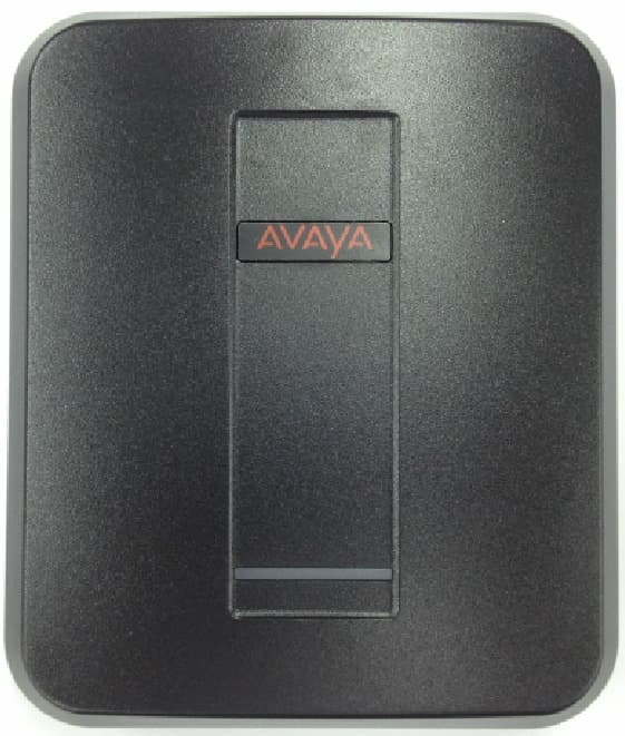
Click to zoom
Application Details
- Equipment Class
- PUB - Part 15 Unlicensed PCS Base Station
- Date of Grant
- Dec 05, 2012
- Application Purpose
- Original Equipment
- Date of Application
- Dec 05, 2012
- Equipment Note
- 1.9GHz UPCS CORDLESS PHONE-REPEATER
- Frequency Range
- 1921.53600000 - 1928.44800000
- Company
- Uniden America Corporation
- Country
- United States
Documents & Files
Document Text
Text extracted from the exhibit documents filed with the FCC. Open a document above to read the original.
Users Manual
Model: D100 DECT NA Model: D100 DECT Repeater NA Model: D160 DECT Handset NA July 2012 - Avaya IMPORTANT NOTICE Read all safety, installation, and user documentation prior to installing or operating this product. To view and download safety, installation, and user documentation go to: http://support.avaya.com. All information is subject to change without notice. Always check Avaya’s Support web site for updates – http://support.avaya.com. Important Safety Instructions When using your telephone equipment, basic safety precautions should always be followed to reduce the risk of fire, electric shock and injury to persons, including the following: This unit is NOT waterproof. DO NOT expose it to rain or moisture. Do not use this product near water, for example, near a bath tub, wash bowl, kitchen sink or laundry tub, in a wet basement or near a swimming pool. Avoid using a telephone (other than a cordless type) during an electrical storm. There may be a remote risk of electric shock from lightning. Do not use the telephone to report a gas leak in the vicinity of the leak. Use only the power cord and batteries indicated in the manual. Do not dispose of batteries in a fire. They may explode. Check with local codes for possible special disposal instructions. Do not place the handset in any charging cradle without the battery installed and the battery cover securely in place. SAVE THESE INSTRUCTIONS! CAUTION! Risk of explosion if battery is replaced by an incorrect type! Dispose of used batteries according to the instructions. Do not open or mutilate the battery. Disconnect the battery before shipping this product. Rechargeable Battery Warning If your equipment contains a rechargeable Nickel-Metal-Hydride (Ni-MH) battery; Nickel is a chemical known to the state of California to cause cancer. Do not short-circuit the battery. The batteries in this equipment may explode if disposed of in a fire. Do not charge the batteries in any charger other than the one specified in the owner's manual. Using another charger may damage the battery or cause it to explode. As part of our commitment to protecting our environment and conserving natural resources, Uniden voluntarily participates in an RBRC® industry program to collect and recycle used Ni- MH batteries within the United States. Please call 1-800-8-BATTERY for information on Ni-MH battery recycling in your area. (RBRC® is a registered trademark of the Rechargeable Battery Recycling Corporation.) Rechargeable batteries must be recycled or disposed of properly. COMPLIANCE INFORMATION FCC Part 15 Information This device complies with part 15 of the FCC rules. Operation is subject to the following two conditions: (1) This device may not cause harmful interference, and (2) This device must accept any interference received, including interference that may cause undesired operation. Privacy of communications may not be ensured when using this phone. FCC PART 15.105(b): Note: This equipment has been tested and found to comply with the limits for a Class B digital device, pursuant to part 15 of the FCC Rules. These limits are designed to provide reasonable protection against harmful interference in a residential installation. This equipment generates, uses and can radiate radio frequency energy and, if not installed and used in accordance with the instructions, may cause harmful interference to radio communications. However, there is no guarantee that interference will not occur in a particular installation. If this equipment does cause harmful interference to radio or television reception, which can be determined by turning the equipment off and on, the user is encouraged to try to correct the interference by one or more of the following measures: Reorient or relocate the receiving antenna. Increase the separation between the equipment and receiver. Connect the equipment into an outlet on a circuit different from that to which the receiver is connected. Consult the dealer or an experienced radio/TV technician for help. FCC RF Exposure Information This product complies with FCC radiation exposure limits under the following conditions: The base must be placed to allow a minimum of 20 cm (8 inches) between the antenna and all persons during normal operation. The base must not be collocated or operated in conjunction with any other antenna or transmitter. The handset is designed for body-worn operation and meets FCC RF exposure guidelines when used with any belt clip, carrying case, or other accessory supplied with this product. (All necessary accessories are included in the package; any additional or optional accessories are not required for compliance with the guidelines.) Third party accessories (unless approved by the manufacturer) should be avoided as these might not comply with FCC RF exposure guidelines. Industry Canada (I.C.) Notice Terminal equipment NOTICE: This equipment meets the applicable Industry Canada Terminal Equipment Technical Specifications. This is confirmed by the registration number. The abbreviation IC before the registration number signifies that registration was performed based on a Declaration of Conformity indicating that Industry Canada technical specifications were met. It does not imply that Industry Canada approved the equipment. Radio equipment The term IC before the radio certification number only signifies that Industry Canada technical specifications were met. Operation is subject to the following two conditions: (1) this device may not cause interference, and (2) this device must accept any interference, including interference that may cause undesired operation of the device. "Privacy of communications may not be ensured when using this telephone". Environmental Requirements Only use the cordless telephone in temperatures between -10 ºC to +50 ºC (+14 ºF to +122 ºF). Avoid exposing the cordless telephone to direct sunlight or close to other heat sources. Do not expose the cordless telephone to open flame. Keep the cord…
Text truncated - open the document above for the full version.
Cover Letter(s)
FCC Part 15D – Compliance Information amwuu279_part 15d declarations.doc 6-Feb-2012 page 1 (4) rev.1.5 EUT AND PRODUCT INFORMATION Type of Equipment UPCS (DECT 6.0) Applicant Name Uniden America Corporation Address 4700 Amon Carter Blvd, Fort Worth, Texas 76155 U.S.A Contact Jon Suehiro FP PP Repeater EUT Type/System FCC ID AMWUU279 Industry Canada ID 513C-UU279 Model name D100 DECT Repeater NA HW Version 1.0 SW Version 0.23 Max antenna Gain +2dBi Can the EUT be Initiating Device YES YES YES Does the EUT transmit signaling channels YES YES YES Max number of slots in use simultaneously 8 Test standard: FCC part 15D RSS-213, Issue 2 / RSS-GEN, Issue 3 Frequency Band 1921.536 – 1928.448 MHz # of RF Channels 5 Frame Period 10 ms Max. Burst length 10 ms Min. Burst Length 10 ms # of System Channels 60 (12 duplex channels per RF carrier) Operating Mode Simplex Duplex FCC Part 15D – Compliance Information amwuu279_part 15d declarations.doc 6-Feb-2012 page 2 (4) rev.1.5 ANTENNAS Base (FP) Repeater Antenna Type Internal External 1 Dipole 2 Dipole 3 4 Does RX and TX use the same antenna(s)? Yes No Handset (PP) Antenna Type Internal External 1 2 Does RX and TX use the same antenna(s)? Yes No ANTENNA DIVERSITY Antenna Diversity Supported TX RX Base (FP) Repeater 1 2 3 4 Handset (PP) 1 2 VOLTAGE AND TEMPERATURE RANGES VOLTAGES FP PP Repeater Nominal Voltage 120V AC Cut-Off Voltage (if applicable) N/A POWER SOURCE Type Manufacturer Base or Repeater AC Adapter Ten Pao International Ltd. Handset (PP) (charger) Data Connections PSTN Others (please specify) .... FCC Part 15D – Compliance Information amwuu279_part 15d declarations.doc 6-Feb-2012 page 3 (4) rev.1.5 ANCILLARY EQUIPMENT Description Type Manufacturer HOST DEVICE Description Type Manufacturer ADDITIONAL INFORMATION FCC Part 15D – Compliance Information amwuu279_part 15d declarations.doc 6-Feb-2012 page 4 (4) rev.1.5 MANUFACTURERS DECLARATIONS FCC part 15.323 (c)(5) The applicant declares that the system in this application has more than 40 duplex system access channels defined, and that the system is operating in Least Interfered Channel (LIC) mode in accordance with this section. Applicant Agrees Yes No FCC part 15.323 (c)(5) No device or group of co-operating devices located within 1m of each other shall during any frame period occupy more than 6 MHz of aggregate bandwidth, or alternatively, more than one third of the time and spectrum windows defined by the system. Applicant Agrees Yes No FCC part 15.323 (c)(10) The applicant hereby declares that the system in this application does use the criteria of (c)(10) of this section. Applicant Agrees Yes No FCC part 15.323 (c)(11) The applicant hereby declares that system in this application does not use the criteria of (c)(11) of this section. Applicant Agrees Yes No FCC part 15.323 (c)(12) The provisions of (c)(10) or (c)(11) of this section shall not be used to extend the range of spectrum occupied over space or time for the purpose of denying fair access to spectrum to other devices. Applicant Agrees Yes No FCC part 15.307 (b) The Applicant is a participating member of UTAM, Inc. and will provide an affidavit from UTAM, Inc. certifying this. Confirmed By Applicant Yes No ADDITIONAL REMARKS: > DECLARED BY: > Date Nov. 16, 2012 > Name (print) Jon Suehiro Signature
Cover Letter(s)
Uniden America Corporation 4700 Amon Carter Blvd. Fort Worth, TX 76155 817-858-3300 Fax: 817-858-3328 REQUEST FOR CONFIDENTIALITY November 16, 2012 To: Federal Communications Commission Equipment Authorization Branch, Lab Div., OET 7435 Oakland Mills Road Columbia, Maryland 21046 Subject: Data for FCC Certification Applicant: Uniden America Corporation 4700 Amon Carter Blvd. Fort Worth, Texas 76155 Jon Suehiro, Manager - Engineering and Regulatory Affairs TYPE OF EQUIPMENT: 1.9GHz UPCS Cordless Telephone – Repeater FCC IDENTIFIERS: AMWUU279 Dear Sir or Madam: Some of the material included in this application contains trade secrets and proprietary information not customarily released to the public. Because public disclosure of the material might be harmful to the applicant and provide unjustified benefits to its competitors, it is requested that the following be withheld from public disclosure: Circuit Description – file: AMWUU279_Circuit Description.pdf Schematic Diagram – file: AMWUU279_Schematic Diagram.pdf Block Diagram - file: AMWUU279_Block Diagram.pdf Trade secrets and proprietary information can be held confidential. Therefore, we wish to invoke the act under the provisions of 47CFR, Sections 0.457(d) and 0.459. Please contact the undersigned if you have any questions or need any further information. Regards, Jon Suehiro Manager, Engineering and Regulatory Affairs
External Photos
“ ““ “D100 DECT D100 DECT D100 DECT D100 DECT Repeater Repeater Repeater Repeater NA NANA NA” ”” ”External Photos External PhotosExternal Photos External Photos Front View (“D100 DECT Repeater NA”) Rear View (“D100 DECT Repeater NA”) Rear Cover Opened (“D100 DECT Repeater NA”) Connect AC Adapter Jack (“D100 DECT Repeater NA”) Rear Cover Closed (“D100 DECT Repeater NA”)
ID Label/Location Info
Equipment Identification Label (D100 DECT Repeater NA) Equipment Labels: The following markings are permanently affixed to the Repeater Unit: 1) 36.5 mm(W) x 12.5 mm(H) by Label 2) 21.5 mm(W) x 5 mm(H) by Label 3) 48 mm(W) x 25 mm(H) by Label 4) 19.5 mm(W) x 9.5 mm(H) by Engraving 5) 12.5 mm(W) x 6.0 mm(H) by Engraving
Internal Photos
D100 DECT D100 DECT D100 DECT D100 DECT Repeater Repeater Repeater Repeater NA NANA NA” ”” ”Internal InternalInternal Internal Photos Photos Photos Photos Rear Cover Opend (“D100 DECT Repeater NA”) Shield Case Opened [Bottom view] (“D100 DECT Repeater NA”) Main PCB Top View (“D100 DECT Repeater NA”) Shield Case Opened [Top view] (“D100 DECT Repeater NA”)
RF Exposure Info
FCC ID: AMWUU279 MPE Calculation for FCC Uncontrolled Environment Formula from page 18 of OET Bulletin 65, Edition 97 -01 where: S = power density P = power input to the antennaG = power gain of the antenna in the direction of i nterest relative to an isotropic radiator R = distance to the center of radiation of the ante nna Source Based Time Averaged Duty Cycle is 100% in ca lculation below Maximum peak output power at antenna input terminal : 19.90 (dBm) Maximum peak output power at antenna input terminal : 0.098 (W) Maximum antenna gain: 0.80 (dBi) Maximum antenna gain: 1.202 (numeric) Prediction distance: 20 (cm) Prediction frequency: 1925 (MHz) Time Averaged Duty Cycle 100 % MPE limit for uncontrolled exposure at prediction f requency: 10.00 (W/m^2) Power density at prediction frequency: 0.0234 (mW/cm^2) Power density at prediction frequency: 0.234 (W/m^2) Maximum allowable antenna gain: 17.11 (dBi) Margin of Compliance: 16.31 (dB) 2 4 R PG S π =
Test Report
Nemko AS, Gaustadalléen 30, P.O.Box 73 Blindern, NO-0314 Oslo Norway T +47 22 96 03 30 F +47 22 96 05 50 Enterprise number NO974404532 Visiting address: Nemko Kjeller, Instituttveien 6, P.O.Box 96, NO-2027 Kjeller Norway T +47 64 84 57 00 F +47 64 84 57 05 Test report no. : 220964-2 Item tested : DRS 100 DECT Repeater NA Type of equipment : UPCS Wireless Relay Station FCC ID : AMWUU279 Client : Uniden America Corporation FCC Part 15, subpart D Isochronous UPCS Device 1920 - 1930 MHz Industry Canada RSS-213, Issue 2 2 GHz Licence-exempt Personal Communications Service Devices (LE-PCS) 2 November 2012 Authorized by : .......................... .................... Jan G Eriksen Technical Verificator TEST REPORT FCC part 15D Report no.: 220964-2 FCC ID: AMWUU279 Nemko AS, N-2007 Kjeller Page 2 (50) CONTENTS 1 GENERAL INFORMATION ............................................................................................................... 3 1.1 Testhouse Info ................................................................................................................................... 3 1.2 Client Information .............................................................................................................................. 3 1.3 Manufacturer (if other than client) ...................................................................................................... 3 2 TEST INFORMATION ....................................................................................................................... 4 2.1 Tested Item........................................................................................................................................ 4 2.2 Description of Tested Device ............................................................................................................. 4 2.3 Exposure Evaluation .......................................................................................................................... 4 2.4 Test Environment .............................................................................................................................. 5 2.5 Test Period ........................................................................................................................................ 5 2.6 Test Engineer(s) ................................................................................................................................ 5 2.7 Test Equipment ................................................................................................................................. 5 2.8 Other Comments ............................................................................................................................... 5 3 TEST REPORT SUMMARY .............................................................................................................. 6 3.1 General .............................................................................................................................................. 6 3.2 Test Summary ................................................................................................................................... 7 4 TEST RESULTS ................................................................................................................................ 8 4.1 Power Line Conducted Emissions ..................................................................................................... 8 4.2 Coordination with fixed microwave .................................................................................................. 10 4.3 Digital Modulation Techniques ........................................................................................................ 10 4.4 Labeling Requirements ................................................................................................................... 10 4.5 Antenna Requirement...................................................................................................................... 11 4.6 Channel Frequencies ...................................................................................................................... 11 4.7 Automatic Discontinuation of Transmission .................................................................................... 12 4.8 Peak Power Output ......................................................................................................................... 13 4.9 Emission Bandwidth B ..................................................................................................................... 18 4.10 Power Spectral Density ................................................................................................................... 21 4.11 In-Band Unwanted Emissions, Conducted ...................................................................................... 24 4.12 Out-of-band Emissions, Conducted................................................................................................. 26 4.13 Carrier Frequency Stability .............................................................................................................. 30 4.14 Frame Repetition Stability ............................................................................................................... 31 4.15 Frame Period and Jitter ................................................................................................................... 31 4.16 Monitoring Threshold, Least Interfered Channel ............................................................................. 33 4.17 Threshold Monitoring Bandwidth ..................................................................................................... 35 4.18 Reaction Time and Monitoring Interval ............................................................................................ 36 4.19 Time and Spectrum Window Access Procedure ...........................................................…
Text truncated - open the document above for the full version.
Test Setup Photos
FCC ID: AMWUU279 Project no.: 220964 Page 1 of 1 PHOTOS OF TEST SET-UP Antenna Gain test Power line Conducted Emissions Test
Contact Information
Applicant
Paul Roby
Test Firm
Nemko ASFrode Sveinsen
Technical Specifications
| # | Rule Parts | Frequency Range | Power Output |
|---|---|---|---|
| 1 | 15D | 1.92 GHz - 1.93 GHz | 98.00 mW |
Other Applications from Uniden America Corporation
AMWUA2405
Apr 15, 2026RADAR DETECTOR
Equipment Class
JBP - Part 15 Class B Computing Device PeripheralAMWUA2406
Apr 15, 2026RADAR DETECTOR
Equipment Class
JBP - Part 15 Class B Computing Device PeripheralAMWUA2402
Jul 23, 2024RADAR DETECTOR
Equipment Class
CRD - Part 15 Radar Detector
AMWUA2404
Feb 17, 2024Wi-Fi Bluetooth Combo Module
Equipment Class
DTS - Digital Transmission System
AMWUA2301
Feb 15, 2023RADAR DETECTOR
Equipment Class
CRD - Part 15 Radar Detector