AMWUU499UPCS Handset DCX100
Uniden America Corporation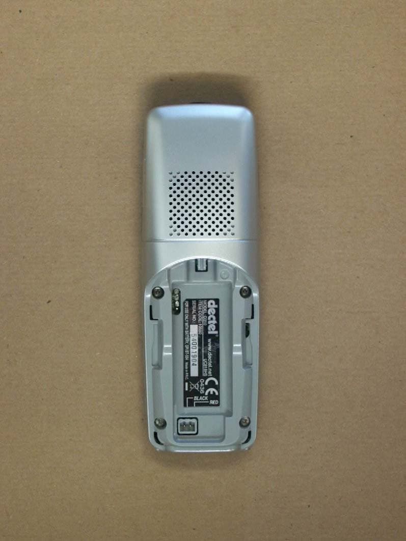
Click to zoom
Application Details
- Equipment Class
- PUE - Part 15 Unlicensed PCS portable Tx held to ear
- Date of Grant
- Jun 15, 2006
- Application Purpose
- Original Equipment
- Date of Application
- Jun 15, 2006
- Equipment Note
- UPCS Handset DCX100
- Frequency Range
- 1921.54000000 - 1927.45000000
- Company
- Uniden America Corporation
- Country
- United States
Documents & Files
Document Text
Text extracted from the exhibit documents filed with the FCC. Open a document above to read the original.
Users Manual
UU01499BZ_1 6/16/06 7:13 PM Page i Welcome Congratulations on your purchase of the Uniden DCX100 accessory handset and charger. This expansion handset is compatible with models in the following series: DECT1060, DECT1060-2, DECT1080, and DECT1080-2. You can place this fully featured cordless handset anywhere your home has AC power. Note: Illustrations in this manual are used for explanation purposes. Some illustrations may differ from the actual unit. Accessibility Uniden provides a customer service hotline for accessibility questions. If you have a disability and need customer service assistance or if you have any questions about how Uniden’s products can accommodate persons with disabilities, please call the accessibility voice/TTY line: 1-800-874-9314. A representative is available to talk to you M-F, 8:00 am to 5:00 pm, CST. After hours, you can leave us a message, and we will call you back. Information is also available on our website, www.uniden.com, under the “Accessibility” link. Important! The DCX100 accessory handset will not operate until it is registered to a Uniden main base. This manual describes how to set up your new accessory handset; for more detailed instructions on operating your new handset, please refer to the manual supplied with your base. Uniden ® is a registered trademark of Uniden America Corporation. [1] UU01499BZ_1 6/16/06 7:13 PM Page 1 Terminology Used in this Manual Checking the Package Contents Make sure your package contains the following items. If any items are missing or damaged, contact our Customer Service Hotline. See page 10 for contact information. • Cordless Handset • Charging Cradle • AC Adapter, model # AD-0005 (Input: 120V AC 60 Hz / Output: 9V DC 210 mA) • Rechargeable NiMH Battery Pack, model # BT-1002 (Capacity: 800 mAh, 2.4V) • Printed Material Installing Your Accessory Handset Follow these steps to get your new handset ready to use. Step 1: Connect the Charger 1Connect the AC adapter (AD-0005) to the DC INjack and to a standard 120V AC wall outlet. 2Set the charger on a desk or tabletop. [2] Base Charger Accessory Handset Standby Talk The main part of the phone that connects to your phone line and lets you make and receive calls. A cradle that charges an accessory handset. It connects to power but not to a phone line. A handset that works with an expandable phone base. Accessory handsets must be registered to a base. The handset is not in use. If it is off the cradle, no line has been activated. No dial tone is present. A telephone line has been activated on the handset enabling a dial tone. UU01499BZ_1 6/16/06 7:13 PM Page 2 •Use only the supplied AC adapter (AD-0005). Do not use other AC adapters. • Place the charger close to the AC outlet so that you can unplug the AC adapter easily. Step 2: Install the Batteries and charge your new handset for 15-20 hours 1Remove the battery compartment cover. Press down on the semi-circle indent and slide the cover off. 2Charge the battery for 15-20 hours before using. To charge the batteries, place the handset on the charger. While charging, the symbol scrolls. When the battery is fully charged and the phone is off the cradle, all the bars of the battery symbol will be filled. If the symbol does not appear, reposition the handset in the charger, ensuring that the charging points contact. NOTE: Once your handset is fully charged, your phone is designed for the charge LED to turn off for approximately 4 seconds during the following instances: 1) just after reaching a full charge 2) 1 minute after reaching a full charge 3) every 5 minutes after reaching a full charge To alleviate the charge LED from blinking on the charger base, you can simply remove the handset from the charging cradle. You may also select to leave the handset in the cradle which will not damage the unit. Once fully charged, you may notice the charge LED light will turn off for 4 seconds every 5 minutes. This is normal operation and does not mean your unit is defective. [3] UU01499BZ_1 6/16/06 7:13 PM Page 3 • Use only the Uniden battery supplied with your phone. • Recharge your handset on a regular basis by returning the handset to the charger after each phone call. Step 3: Register the Handset YOU NEED TO REGISTER THE DCX100 TO THE MAIN BASE BEFORE USE! For Main Base Models DECT1060/DECT1060-2/DECT1080/ DECT1080-2. When you register a new handset to your base, you will be asked to enter the base PIN code. The pre-set PIN code is 0000. If you wish, you can change this code, see owner's manual for detailed instruction. Before registering, make sure that you have the base and handset in front of you. Also, make sure all handsets and the base are in standby mode. On the handset you want to register: 1Press to access the main menu. 2Press up or down key until “ Add.Settings” is displayed and press . Pressor to display “ Register” and press . Pressor to select your base number and press . On your original base: Press and hold Find HSfor approx. 3 seconds. You are now in ‘registration mode’. If the base already has the maximum number of handsets (6) registered to it, you will need to de-register one of the existing handsets before you can register the new handset. See the section on the next page for de-registering handsets. [4] UU01499BZ_1 6/16/06 7:13 PM Page 4 On the handset you want to register: Enter the base PIN code. Pre-set base PIN code is 0000. You will hear a confirmation tone when registration is complete. When in standby mode, the new handset number will be displayed. The handset will automatically be allocated with the next available handset number. If registration is unsuccessful, the display will show Not Registered and you will need to follow the registration procedure again. De-register a Handset or a Base If you have more than one handset registered to your base or more than one base registered to your handset(s), you can de- register both the handset from the base or the base from the handset. Before deregistering, make…
Text truncated - open the document above for the full version.
Cover Letter(s)
Declaration concerning Antenna Specification June 9, 2006 To: Federal Communications Commission Equipment Authorization Branch Laboratory Division Office of Engineering and Technology 7435 Oakland Mills Road Columbia, Maryland 21046 Applicant: Uniden America Corporation 181 N. Country Club Road, P.O. Box 580 Lake City, South Carolina 29560 James R. Haynes, Vice President, Engineering and Regulatory Affairs Dear Sir or Madam: I hereby declare that the product identified by the FCC Identifier AMWUU499 will fulfill the requirements for FCC testing as related to the antenna type. Additionally, this product conforms to the FCC recommendation with regards to the internal antenna type. It is specified as: Antenna type: Internal inverted -F wire antenna (1/4 wave antenna) Gain of the antenna.......< 3dBi Frequency range ...........1920 -1930MHz. The mounting of the antenna is fixed to the radio module and no other antenna should be used. Please contact the undersigned if you have any questions or need any further information. Regards, James R. Haynes Vice President, Engineering and Regulatory Affairs
Cover Letter(s)
REQUEST FOR CONFIDENTIALITY April 17, 2006 To: Federal Communications Commission Equipment Authorization Branch Laboratory Division Office of Engineering and Technology 7435 Oakland Mills Road Columbia, Maryland 21046 Subject: Data for FCC Certification Applicant: Uniden America Corporation 181 N. Country Club Road, P.O. Box 580 Lake City, South Carolina 29560 James R. Haynes, Vice President, Engineering and Regulatory Affairs TYPE OF EQUIPMENT: Unlicensed Personal Communications Services (PCS) Devices FCC RULES: Part 15, Subpart D FCC IDENTIFIER: AMWUU499 Dear Sir or Madam: Some of the material included in this application contains trade secrets and proprietary information not customarily released to the public. Because public disclosure of the material might be harmful to the applicant and provide unjustified benefits to its competitors, it is requested that the following be withheld from public disclosure: Operational Description - Circuit Description - Schematic Diagrams - Block Diagrams Trade secrets and proprietary information can be held confidential. Therefore, we wish to invoke the act under the provisions of 47CFR, Sections 0.457(d) and 0.459. Please contact the undersigned if you have any questions or need any further information. Regards, James R. Haynes Vice President, Engineering and Regulatory Affairs
Cover Letter(s)
1) if applicable rev. 1.4 UPCS_DECTbased_ICS_HANDSET.doc page 1 (6) -ETS- Dr. Genz GmbH, Germany Storkower Straße 38c D-15526 Reichenwalde b. Berlin Telephone: +49.33631.888.00 Fax: +49.33631.888.640 ELECTRONIC TECHNOLOGY SYSTEMS DR.GENZ GMBH UPCS (DECT based) – Implementation Conformance Statement Description : Handset Model : DCX100 (FCC ID: AMWUU499) Use : FP PP Repeater System Type HW version WORKING STAGE SW version Ver. 0.02 RFPI / PIN Decl. emission BW 1.4 MHz Decl. lower threshold -82.4 dBm DUT Decl.upper threshold 1) - 62.4 dBm Product information Standard: FCC part 15D other: Frequency band: 1920 – 1930 MHz other: Number of RF channels: 5 Number of logical channels: 60 (time and spectrum windows) Used slot type: single double Used slot(s): even odd For doubleslot connection even and odd slots are used Operating mode: simplex duplex other: 1) if applicable rev. 1.4 UPCS_DECTbased_ICS_HANDSET.doc page 2 (6) -ETS- Dr. Genz GmbH, Germany Storkower Straße 38c D-15526 Reichenwalde b. Berlin Telephone: +49.33631.888.00 Fax: +49.33631.888.640 ELECTRONIC TECHNOLOGY SYSTEMS DR.GENZ GMBH Antennas: Antenna Type Gain [dBi] internal external 1 2 3 FP: Do Tx and Rx use the same antenna(s)?: Yes No Antenna Type Gain [dBi] internal external 1 Metal < 3 2 3 PP: Do Tx and Rx use the same antenna(s)?: Yes No Antenna diversity: 1) Diversity supported Antenna Tx Rx 1 2 FP 3 1 2 Product information PP 3 1) if applicable rev. 1.4 UPCS_DECTbased_ICS_HANDSET.doc page 3 (6) -ETS- Dr. Genz GmbH, Germany Storkower Straße 38c D-15526 Reichenwalde b. Berlin Telephone: +49.33631.888.00 Fax: +49.33631.888.640 ELECTRONIC TECHNOLOGY SYSTEMS DR.GENZ GMBH Supply and supported temperature ranges (Manufacturer declaration): FP PP Repeater U normal [V] 2.4 V U min [V] 2.1 V U max [V] 2.8 V T min [°C] 0 T max [°C] +40 Power Source Type Manufacturer FP or WRS PP (charger) Basestation ?? Data connection: PSTN other Used radio module 1) : Type : Manufacturer : Ancillary equipment 1) : Description : Type : Manufacturer : Product information Host device 1) : Description : Type : Manufacturer : 1) if applicable rev. 1.4 UPCS_DECTbased_ICS_HANDSET.doc page 4 (6) -ETS- Dr. Genz GmbH, Germany Storkower Straße 38c D-15526 Reichenwalde b. Berlin Telephone: +49.33631.888.00 Fax: +49.33631.888.640 ELECTRONIC TECHNOLOGY SYSTEMS DR.GENZ GMBH Control software 1) : Name : Version : Manufacturer : Product information Additional remarks: 1) if applicable rev. 1.4 UPCS_DECTbased_ICS_HANDSET.doc page 5 (6) -ETS- Dr. Genz GmbH, Germany Storkower Straße 38c D-15526 Reichenwalde b. Berlin Telephone: +49.33631.888.00 Fax: +49.33631.888.640 ELECTRONIC TECHNOLOGY SYSTEMS DR.GENZ GMBH FCC 15.323 (c) (5): This device or group of co-operating devices located within 1 meter of each other shall not during any frame period occupy more than 6 MHz of aggregate bandwidth, or alternatively more than one third of the time and spectrum windows defined by the system. Manufacturer agrees: Yes No FCC 15.323 (c) (12): This device shall not use the provisions of (c) (10) or (c) (11) to extend the range of spectrum occupied over space or time for the purpose of denying fair access to spectrum to other devices. Manufacturer agrees: Yes No FCC 15.307 (b): The applicant is a participating member of UTAM, Inc. and will provide a related affidavit from UTAM, Inc. in course of certification. Confirmation by applicant: Yes No FCC 15.319 (f) Automatic discontinuation of transmission: This device shall automatically discontinue transmission in case of either absence of information to transmit or operational failure. Automatic break off the transmissions means break off of connection and break of transmissions which are not control and signalling information or repetitive codes of complete frame or burst intervals. In case of devices using basics of DECT technology at least fixed parts and repeaters are using control and signalling information without direct connection to their remote station. Please fill in the table below with the reaction of the EUT (FP and/or PP) using A, B or C. Reaction of EUT Situation FP PP Verdict 1 Switch-off counter part A 2 Hook-on by counter part Not possible 3 Switch-off by EUT A 4 Hook-on at EUT side A 5 Remove power from EUT A 6 Remove power from counterpart A Manufacturer declarations A – Connection break down, cease of transmit B – Connection break down, EUT transmits signalling information C – Connection break down, counter part transmits signalling information 1) if applicable rev. 1.4 UPCS_DECTbased_ICS_HANDSET.doc page 6 (6) -ETS- Dr. Genz GmbH, Germany Storkower Straße 38c D-15526 Reichenwalde b. Berlin Telephone: +49.33631.888.00 Fax: +49.33631.888.640 ELECTRONIC TECHNOLOGY SYSTEMS DR.GENZ GMBH Supplement Additional remarks: Declared by: Date: 4-11-2006 Name (print): Yoshinobu Fujiwara Signature:
External Photos
ELECTRONIC TECHNOLOGY SYSTEMS DR.GENZ GMBH ETS Dr. Genz GmbH, Germany Registration number: G0M20604-0398-C-1 Page 1 of 11 Appendix A. Pictures ELECTRONIC TECHNOLOGY SYSTEMS DR.GENZ GMBH ETS Dr. Genz GmbH, Germany Registration number: G0M20604-0398-C-1 Page 2 of 11 ELECTRONIC TECHNOLOGY SYSTEMS DR.GENZ GMBH ETS Dr. Genz GmbH, Germany Registration number: G0M20604-0398-C-1 Page 3 of 11
ID Label/Location Info
Equipment Identification Label Equipment Labels: The following Labels are permanently affixed to the equipment. 1) HANDSET: 31.5 mm (W) X 15.2 mm (H)
Internal Photos
ELECTRONIC TECHNOLOGY SYSTEMS DR.GENZ GMBH ETS Dr. Genz GmbH, Germany Registration number: G0M20604-0398-C-1 Page 4 of 11 ELECTRONIC TECHNOLOGY SYSTEMS DR.GENZ GMBH ETS Dr. Genz GmbH, Germany Registration number: G0M20604-0398-C-1 Page 5 of 11 ELECTRONIC TECHNOLOGY SYSTEMS DR.GENZ GMBH ETS Dr. Genz GmbH, Germany Registration number: G0M20604-0398-C-1 Page 6 of 11 ELECTRONIC TECHNOLOGY SYSTEMS DR.GENZ GMBH ETS Dr. Genz GmbH, Germany Registration number: G0M20604-0398-C-1 Page 7 of 11
RF Exposure Info
ELECTRONIC TECHNOLOGY SYSTEMS DR. GENZ GMBH TEST - REPORT SAR Compliance Test Report Test report no.: G0M20604-0398-S-8 SAR ELECTRONIC TECHNOLOGY SYSTEMS STORKOWER STRASSE 38C, D-15526 REICHENWALDE B. BERLIN DR. GENZ GMBH PHONE +49-33631-888 00 FAX +49-33631-888 660 ETS Dr. Genz GmbH, Germany Registration number: G0M20604-0398-S-8 Page 1 of 25 ELECTRONIC TECHNOLOGY SYSTEMS DR.GENZ GMBH TABLE OF CONTENTS 1 General information 1.1 Notes 1.2 Testing laboratory 1.3 Details of approval holder 1.4 Manufacturer 1.5 Application details 1.6 Test item 1.7 Test results 1.8 Test standards 2 Technical test 2.1 Summary of test results 2.2 Test environment 2.3 Test equipment utilized 2.4 Definitions 2.5 Measurement system description 2.6 Test system specification 2.7 Measurement procedure 2.8 Reference points 2.9 Test positions 2.10 Measurement uncertainty 3 Tissue and system verification 3.1 Tissue verification 3.2 System verification 4 Test Results 5 References 6 Appendix ETS Dr. Genz GmbH, Germany Registration number: G0M20604-0398-S-8 Page 2 of 25 ELECTRONIC TECHNOLOGY SYSTEMS DR.GENZ GMBH 1 General Information 1.1 Notes The purpose of conformity testing is to increase the probability of adherence to the essential requirements or conformity specifications, as appropriate. The complexity of the technical specifications, however, means that full and thorough testing is impractical for both technical and economic reasons. Furthermore, there is no guarantee that a test sample which has passed all the relevant tests conforms to a specification. The existence of the tests nevertheless provides the confidence that the test sample possesses the qualities as maintained and that is performance generally conforms to representative cases of communications equipment. The test results of this test report relate exclusively to the item tested as specified in 1.5. The test report may only be reproduced or published in full. Reproduction or publication of extracts from the report requires the prior written approval of the ELECTRONIC TECHNOLOGY SYSTEMS DR. GENZ GMBH. I attest to the accuracy of data. All measurements reported herein were performed by me or were made under my supervision and are correct to the best of my knowledge and belief. I assume full responsibility for the completeness of these measurements and vouch for the qualification of all persons taking them. Tester: 11.05.2006 Mr. Handrik Date ETS-Lab. Name Signature Technical responsibility for area of testing: 11.05.2006 N. Kaspar Date ETS Name Signature ETS Dr. Genz GmbH, Germany Registration number: G0M20604-0398-S-8 Page 3 of 25 ELECTRONIC TECHNOLOGY SYSTEMS DR.GENZ GMBH 1.2 Testing laboratory 1.2.1 Location ELECTRONIC TECHNOLOGY SYSTEM DR. GENZ GMBH (ETS) Storkower Straße 38c D-15526 Reichenwalde b. Berlin Germany Telephone : +49 33631 888 00 Fax : +49 33631 888 660 1.2.2 Details of accreditation status ACCREDITED TESTING LABORATORY DAR-REGISTRATION NUMBER: TTI-P-G 126/96 FCC FILED TEST LABORATORY REG. NO. 96970 BLUETOOTH QUALIFICATION TEST FACILITY (BQTF) ACCREDITED BY BLUETOOTH QUALIFICATION REVIEW BOARD INDUSTRY CANADA FILED TEST LABORATORY REG. NO. IC 3470 A2LA ACCREDITED Certificate Number 1983-01 1.3 Details of approval holder Name : Uniden America Corporation Street : 181 N. Country Club Road P.O. Box 580, Town : Lake City, South Carolina, 29560 Country : USA Telephone : 843-374-3852 Fax : 843-374-8393 Contact : Mr. James R. Haynes E-Mail : [email protected] 1.4 Manufacturer: (if applicable) Name : Street : Town : Country : ETS Dr. Genz GmbH, Germany Registration number: G0M20604-0398-S-8 Page 4 of 25 ELECTRONIC TECHNOLOGY SYSTEMS DR.GENZ GMBH 1.5 Application details Date of receipt of application : 12.04.2006 Date of receipt of test item : 12.04.2006 Date of test : 08.05.2006 - 09.05.2006 1.6 Test item FCC ID : AMWUU499 Description of test item : DECT 6.0, Handset Type identification : DCX100 / AMWUU499 Brand Name : Brand Name: Uniden Serial number : without; Identical prototype Device category : PUE (Part 15 unlicensed PCS portable TX held to ear) Technical data TX Frequency range : 1921.536 – 1928.448 MHz Max. Conducted RF output power : UPCS / 19.14 dBm (82 mW) Power supply : 2.4 V DC (2*1.2V Ni-Mh AA rechargeable batteries) Antenna Tx : integral Antenna RX : integral Antenna Gain : 3 dBi Antenna Type : Internal inverted -F wire antenna (1/4 wave antenna) Additional information : ./. 1.7 Test Results Max. SAR Measurement : 0.022 W/kg (averaged over 1 gram) This EUT has been shown to be capable of compliance for localized specific absorption rate (SAR) for uncontrolled environment/general population exposure limits specified in ANSI/IEEE Std. C95.1-1992 and had been tested in accordance with the measurement procedures specified in FCC/OET Bulletin 65 Supplement C (2001) and IEEE Std. 1528-2003, December 2003. ETS Dr. Genz GmbH, Germany Registration number: G0M20604-0398-S-8 Page 5 of 25 ELECTRONIC TECHNOLOGY SYSTEMS DR.GENZ GMBH 1.8 Test standards Standards : - IEEE Std. 1528-2003, December 2003 FCC Rule Part(s) : - FCC OET Bulletin 65, Supplement C, Edition 01-01 2 Technical test 2.1 Summary of test results Applicable Configuration Handset (Head) X Handset (Body) X Headset (Head) Body Worn Equipment EUT complies with the RF radiation exposure limits of the FCC as shown by the SAR measurement results. These measurements are taken to simulate the RF effects exposure under worst-case conditions. The EUT complies with the requirements in respect to all parameters subject to the test. The test results and statements relate only to the item(s) tested. Please note that the absorption and distribution of electromagnetic energy in the body are very complex phenomena that depend on the mass, shape, and size of the body, the orientation of the body with respect to the field vectors, and the electrical properties of both the body and the environment. Other variables that may play a substantial role in possible biological effects are those that cha…
Text truncated - open the document above for the full version.
RF Exposure Info
ETS Dr. Genz GmbH, Germany Registration number: G0M20604-0398-S-8 Appendix B ELECTRONIC TECHNOLOGY SYSTEMS DR.GENZ GMBH Appendix B Measurement Plots Date/Time: 5/8/2006 15:22:46 Test Laboratory: ELECTRONIC TECHNOLOGY SYSTEMS DR. GENZ GMBH Dipol Valid.1900(h)_250mW 8.5.2006 DUT: Dipole 1900 MHz; Type: D1900V2; Serial: 5d025 Communication System: CW; Frequency: 1900 MHz;Duty Cycle: 1:1 Medium: Head 1900 MHz Medium parameters used: f = 1900 MHz; σ = 1.42 mho/m; ε r = 39.9; ρ = 1000 kg/m 3 Phantom section: Flat Section DASY4 Configuration: z Probe: ET3DV6 - SN1711; ConvF(4.84, 4.84, 4.84); Calibrated: 11/21/2005 z Sensor-Surface: 4mm (Mechanical And Optical Surface Detection) z Electronics: DAE3 Sn522; Calibrated: 11/23/2005 z Phantom: SAM 12; Type: TP-1217; Serial: QD000P40CA z Measurement SW: DASY4, V4.6 Build 23; Postprocessing SW: SEMCAD, V1.8 Build 160 Dipol 1900 (250mW)/Area Scan (61x81x1): Measurement grid: dx=10mm, dy=10mm Maximum value of SAR (interpolated) = 12.2 mW/g Dipol 1900 (250mW)/Zoom Scan (7x7x7)/Cube 0: Measurement grid: dx=5mm, dy=5mm, dz=5mm Reference Value = 93.8 V/m; Power Drift = -0.008 dB Peak SAR (extrapolated) = 17.6 W/kg SAR(1 g) = 10.2 mW/g; SAR(10 g) = 5.41 mW/g Maximum value of SAR (measured) = 11.4 mW/g 0 dB = 11.4mW/g Date/Time: 5/9/2006 09:08:42 Test Laboratory: ELECTRONIC TECHNOLOGY SYSTEMS DR. GENZ GMBH Dipol Valid.1900(m)_250mW 9.5.2006 DUT: Dipole 1900 MHz; Type: D1900V2; Serial: 5d025 Communication System: CW; Frequency: 1900 MHz;Duty Cycle: 1:1 Medium: Muscle 1900 MHz Medium parameters used: f = 1900 MHz; σ = 1.58 mho/m; ε r = 51.9; ρ = 1000 kg/m 3 Phantom section: Flat Section DASY4 Configuration: z Probe: ET3DV6 - SN1711; ConvF(4.31, 4.31, 4.31); Calibrated: 11/21/2005 z Sensor-Surface: 4mm (Mechanical And Optical Surface Detection) z Electronics: DAE3 Sn522; Calibrated: 11/23/2005 z Phantom: SAM 12; Type: TP-1217; Serial: QD000P40CA z Measurement SW: DASY4, V4.6 Build 23; Postprocessing SW: SEMCAD, V1.8 Build 160 Dipol 1900 (250mW)/Area Scan (61x81x1): Measurement grid: dx=10mm, dy=10mm Maximum value of SAR (interpolated) = 13.8 mW/g Dipol 1900 (250mW)/Zoom Scan (7x7x7)/Cube 0: Measurement grid: dx=5mm, dy=5mm, dz=5mm Reference Value = 90.9 V/m; Power Drift = 0.018 dB Peak SAR (extrapolated) = 20.1 W/kg SAR(1 g) = 11.6 mW/g; SAR(10 g) = 6.04 mW/g Maximum value of SAR (measured) = 13.2 mW/g 0 dB = 13.2mW/g Date/Time: 5/8/2006 08:46:28 Test Laboratory: ELECTRONIC TECHNOLOGY SYSTEMS DR. GENZ GMBH left_ch2_cheek DUT: Uniden America Corporation; Type: DECT 6.0, Handset ; Serial: DCX100 / AMWUU499 Communication System: UPCS single slot; Frequency: 1924.99 MHz;Duty Cycle: 1:24 Medium: Head 1900 MHz Medium parameters used: f = 1924.99 MHz; σ = 1.44 mho/m; ε r = 39.7; ρ = 1000 kg/m 3 Phantom section: Left Section DASY4 Configuration: z Probe: ET3DV6 - SN1711; ConvF(4.54, 4.54, 4.54); Calibrated: 11/21/2005 z Sensor-Surface: 4mm (Mechanical And Optical Surface Detection) z Electronics: DAE3 Sn522; Calibrated: 11/23/2005 z Phantom: SAM 12; Type: TP-1217; Serial: QD000P40CA z Measurement SW: DASY4, V4.6 Build 23; Postprocessing SW: SEMCAD, V1.8 Build 160 DCX100 / AMWUU499/Area Scan (71x131x1): Measurement grid: dx=10mm, dy=10mm Maximum value of SAR (interpolated) = 0.013 mW/g DCX100 / AMWUU499/Zoom Scan (8x8x7)/Cube 0: Measurement grid: dx=5mm, dy=5mm, dz=5mm Reference Value = 2.44 V/m; Power Drift = 0.048 dB Peak SAR (extrapolated) = 0.019 W/kg SAR(1 g) = 0.012 mW/g; SAR(10 g) = 0.00708 mW/g Maximum value of SAR (measured) = 0.013 mW/g 0 dB = 0.013mW/g Date/Time: 5/8/2006 09:19:30 Test Laboratory: ELECTRONIC TECHNOLOGY SYSTEMS DR. GENZ GMBH left_ch2_tilted DUT: Uniden America Corporation; Type: DECT 6.0, Handset ; Serial: DCX100 / AMWUU499 Communication System: UPCS single slot; Frequency: 1924.99 MHz;Duty Cycle: 1:24 Medium: Head 1900 MHz Medium parameters used: f = 1924.99 MHz; σ = 1.44 mho/m; ε r = 39.7; ρ = 1000 kg/m 3 Phantom section: Left Section DASY4 Configuration: z Probe: ET3DV6 - SN1711; ConvF(4.54, 4.54, 4.54); Calibrated: 11/21/2005 z Sensor-Surface: 4mm (Mechanical And Optical Surface Detection) z Electronics: DAE3 Sn522; Calibrated: 11/23/2005 z Phantom: SAM 12; Type: TP-1217; Serial: QD000P40CA z Measurement SW: DASY4, V4.6 Build 23; Postprocessing SW: SEMCAD, V1.8 Build 160 DCX100 / AMWUU499/Area Scan (71x131x1): Measurement grid: dx=10mm, dy=10mm Maximum value of SAR (interpolated) = 0.010 mW/g DCX100 / AMWUU499/Zoom Scan (8x8x7)/Cube 0: Measurement grid: dx=5mm, dy=5mm, dz=5mm Reference Value = 2.27 V/m; Power Drift = 0.035 dB Peak SAR (extrapolated) = 0.014 W/kg SAR(1 g) = 0.00836 mW/g; SAR(10 g) = 0.00468 mW/g Maximum value of SAR (measured) = 0.009 mW/g 0 dB = 0.009mW/g Date/Time: 5/8/2006 11:28:36 Test Laboratory: ELECTRONIC TECHNOLOGY SYSTEMS DR. GENZ GMBH right_ch4_cheek DUT: Uniden America Corporation; Type: DECT 6.0, Handset ; Serial: DCX100 / AMWUU499 Communication System: UPCS single slot; Frequency: 1921.54 MHz;Duty Cycle: 1:24 Medium: Head 1900 MHz Medium parameters used: f = 1921.54 MHz; σ = 1.44 mho/m; ε r = 39.7; ρ = 1000 kg/m 3 Phantom section: Right Section DASY4 Configuration: z Probe: ET3DV6 - SN1711; ConvF(4.54, 4.54, 4.54); Calibrated: 11/21/2005 z Sensor-Surface: 4mm (Mechanical And Optical Surface Detection) z Electronics: DAE3 Sn522; Calibrated: 11/23/2005 z Phantom: SAM 12; Type: TP-1217; Serial: QD000P40CA z Measurement SW: DASY4, V4.6 Build 23; Postprocessing SW: SEMCAD, V1.8 Build 160 DCX100 / AMWUU499/Area Scan (71x131x1): Measurement grid: dx=10mm, dy=10mm Maximum value of SAR (interpolated) = 0.016 mW/g DCX100 / AMWUU499/Zoom Scan (8x8x7)/Cube 0: Measurement grid: dx=5mm, dy=5mm, dz=5mm Reference Value = 2.49 V/m; Power Drift = -0.023 dB Peak SAR (extrapolated) = 0.035 W/kg SAR(1 g) = 0.014 mW/g; SAR(10 g) = 0.00845 mW/g Maximum value of SAR (measured) = 0.016 mW/g 0 dB = 0.016mW/g Date/Time: 5/8/2006 10:24:23 Test Laboratory: ELECTRONIC TECHNOLOGY SYSTEMS DR. GENZ GMBH right_ch2_cheek DUT: Uniden America Corpo…
Text truncated - open the document above for the full version.
Test Report
ELECTRONIC TECHNOLOGY SYSTEMS DR. GENZ GMBH TEST - REPORT FCC PART 15 D for Isochronous UPCS devices RSS-213 for LE-PCS devices FCC ID: AMWUU499 Test report no.: G0M20604-0398-C-1 Certificate 1983-01 ELECTRONIC TECHNOLOGY SYSTEMS STORKOWER STRASSE 38C, D-15526 REICHENWALDE B. BERLIN DR. GENZ GMBH PHONE +49-33631-888 00 FAX +49-33631-888 66 ETS Dr. Genz GmbH, Germany Registration number: G0M20604-0398-C-1 Page 1 of 52 ELECTRONIC TECHNOLOGY SYSTEMS DR.GENZ GMBH TABLE OF CONTENTS 1 General information 1.1 Notes 1.2 Testing laboratory 1.3 Details of approval holder 1.4 Application details 1.5 Test item 1.6 Test standards 2 TECHNICAL TEST 2.1 Summary of test results 2.2 Test environment 2.3 Test equipment utilized 2.4 Examinations and Test Procedures 3 RESULTS OF EXAMINATIONS AND TESTS 3.1. Examinations and Test Procedures 3.1.1 Coordination with fixed microwave service, FCC 15.307 (b) 3.1.2 Reference to Subpart B, FCC 15.309 (b) 3.1.3 Conducted limits AC Power line, FCC 15.315, 15.207; RSS-213 4.2; 6.3 3.1.4 Antenna requirement, FCC 15.317, 15.203 3.1.5 Modulation techniques, FCC 15.319 (b); RSS-213 6.1 3.1.6 Emission bandwidth, FCC 15.323 (a); FCC 15.31 (e); RSS-213 6.4 3.1.7 Peak Transmit Power, FCC 15.319 (c); RSS-213 4.3.1, 6:5 3.1.8 Power spectral density, FCC 15.319 (d); RSS-213 4.3.1, 6:6 3.1.9 Directional gain of the antenna, FCC 15.319 (e); RSS-213 4.1 (e) 3.1.10 Automatic discontinuation of transmission, FCC 15.319 (f); RSS-213 4.3.4 (a) ETS Dr. Genz GmbH, Germany Registration number: G0M20604-0398-C-1 Page 2 of 52 ELECTRONIC TECHNOLOGY SYSTEMS DR.GENZ GMBH 3.1.11 Radio frequency radiation exposure, FCC 15.319 (i); RSS-Gen 5.5 3.1.12 Monitoring threshold; Least interfered channel; FCC 15.323 (c)(2); (c)(5) (c)(9); RSS-213 4.3.4 (b)(2) 3.1.13 Monitoring of intended transmit window and maximum reaction time, FCC 15.323 (c)(1); RSS-213 4.3.4 (b)(1) 3.1.14 Monitoring bandwidth, FCC 15.323 (c)(7); RSS-213 4.3.4 (b)(7) 3.1.15 Random waiting interval, FCC 15.323 (c)(6); RSS-213 4.3.4 (b)(6) 3.1.16 Duration of transmission, FCC 15.323 (c)(3); RSS-213 4.3.4 (b)(3) 3.1.17 Connection acknowledgement, Unacknowledged transmissions, FCC 15.323 (c)(4); RSS-213 4.3.4 (b)(5) 3.1.18 Selected channel confirmation, Segment occupancy; FCC 15.323 (c)(5) 3.1.19 Monitoring antenna, FCC 15.323 (c)(8); RSS-213 4.3.4 (b)(8) 3.1.20 Duplex connections, FCC 15.323 (c)(10); RSS-213 4.3.4 (b)(10) 3.1.21 Alternative monitoring interval for co-located devices, FCC 15.323 (c)(11); RSS-213 4.3.4 (b)(11) 3.1.22 Fair access to spectrum related to (c)(10) and (c)(11), FCC 15.323 (c)(12); RSS-213 4.3.4 (b)(12) 3.1.23 Emissions inside and outside the sub-band, FCC 15.323 (d); RSS-213 6.7 3.1.24 Frame period, FCC 323 (e); RSS-213 4.3.(c). 3.1.25 Frequency stability, FCC 323 (f); RSS-213 6.8 3.1.26 Receiver spurious emissions; RSS-213 6.8 ETS Dr. Genz GmbH, Germany Registration number: G0M20604-0398-C-1 Page 3 of 52 ELECTRONIC TECHNOLOGY SYSTEMS DR.GENZ GMBH 1 General Information 1.1 Notes The purpose of conformity testing is to increase the probability of adherence to the essential requirements or conformity specifications, as appropriate. The complexity of the technical specifications, however, means that full and thorough testing is impractical for both technical and economic reasons. Furthermore, there is no guarantee that a test sample which has Passed all the relevant tests conforms to a specification. Neither is there any guarantee that such a test sample will interoperate with other genuinely open systems. The existence of the tests nevertheless provides the confidence that the test sample possesses the qualities as maintained and that is performance …
Text truncated - open the document above for the full version.
Contact Information
Applicant
Paul Roby
Test Firm
Eurofins Product Service GmbHRobert Kschiwan-Kaspar
Technical Specifications
| # | Rule Parts | Frequency Range | Power Output |
|---|---|---|---|
| 1 | 15D | 1.92 GHz - 1.93 GHz | 82.00 mW |
Other Applications from Uniden America Corporation
AMWUA2405
Apr 15, 2026RADAR DETECTOR
Equipment Class
JBP - Part 15 Class B Computing Device PeripheralAMWUA2406
Apr 15, 2026RADAR DETECTOR
Equipment Class
JBP - Part 15 Class B Computing Device PeripheralAMWUA2402
Jul 23, 2024RADAR DETECTOR
Equipment Class
CRD - Part 15 Radar Detector
AMWUA2404
Feb 17, 2024Wi-Fi Bluetooth Combo Module
Equipment Class
DTS - Digital Transmission System
AMWUA2301
Feb 15, 2023RADAR DETECTOR
Equipment Class
CRD - Part 15 Radar Detector