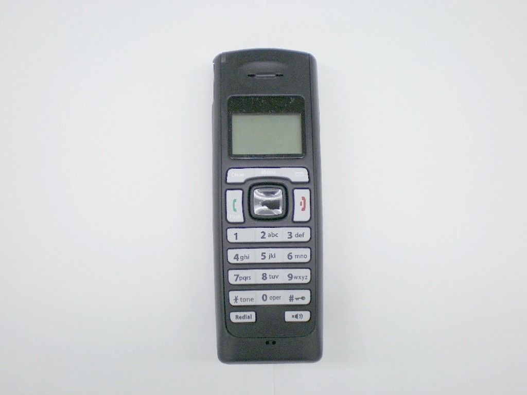
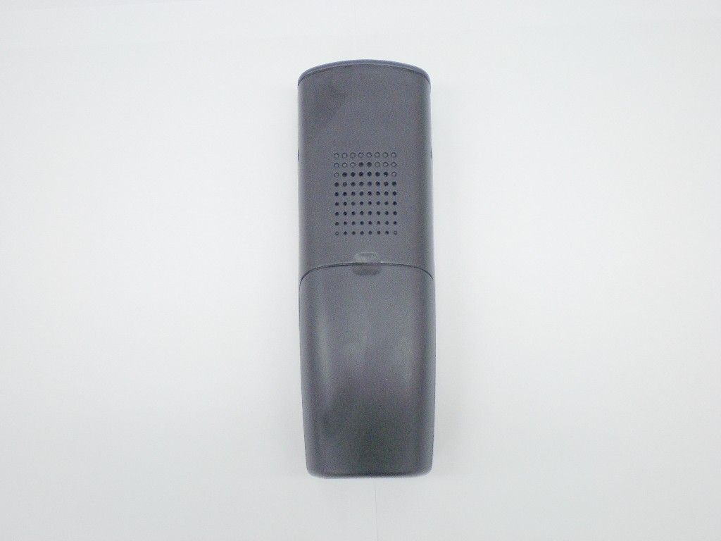
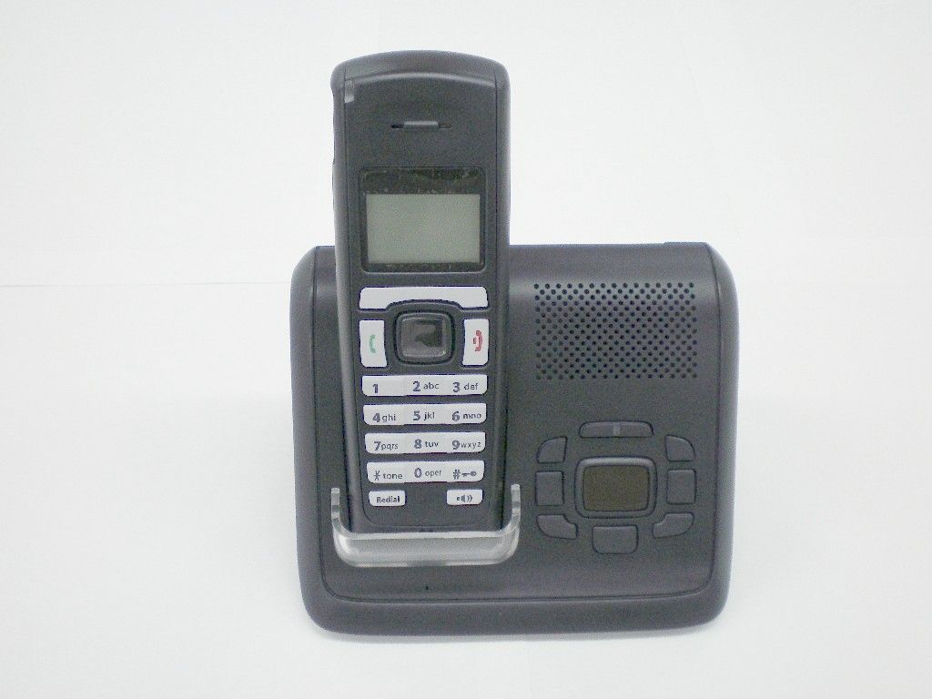
AMWUU6441.9 GHz UPCS CORDLESS TELEPHONE - HANDSET
Uniden America Corporation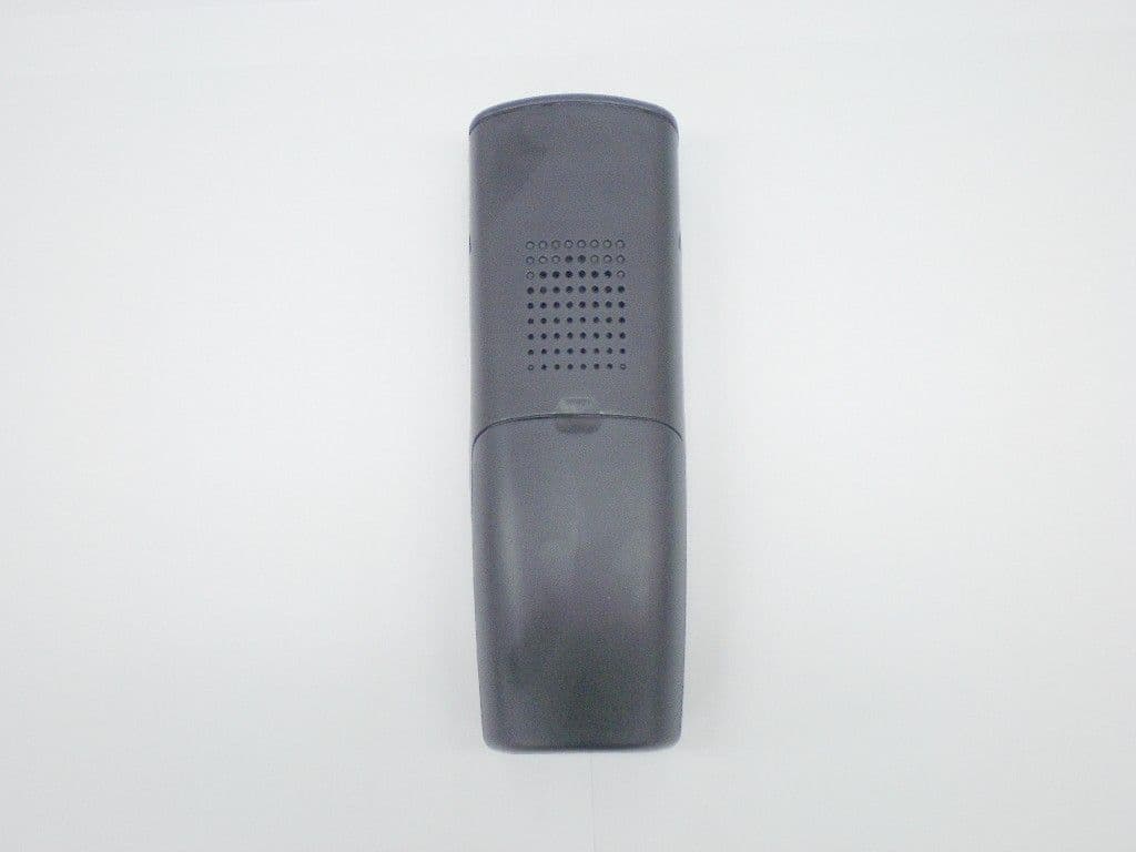
Click to zoom
Application Details
- Equipment Class
- PUE - Part 15 Unlicensed PCS portable Tx held to ear
- Date of Grant
- May 02, 2007
- Application Purpose
- Original Equipment
- Date of Application
- May 02, 2007
- Equipment Note
- 1.9 GHz UPCS CORDLESS TELEPHONE - HANDSET
- Frequency Range
- 1921.53600000 - 1928.44800000
- Company
- Uniden America Corporation
- Country
- United States
Documents & Files
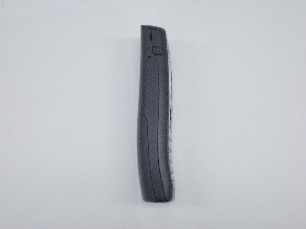
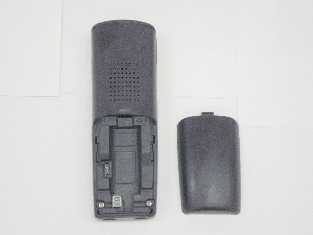
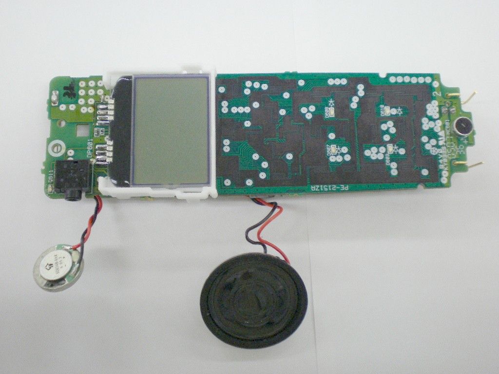
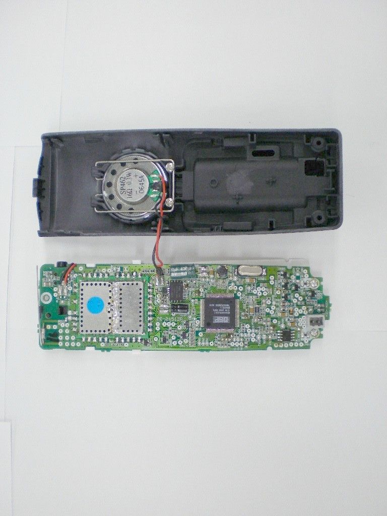
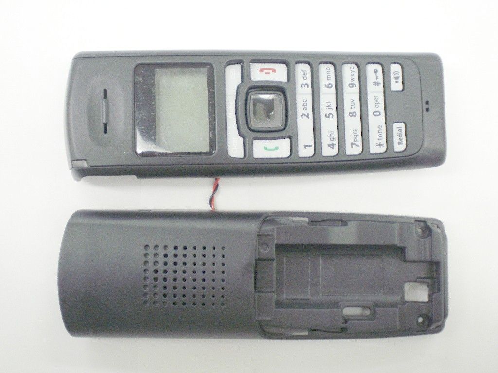
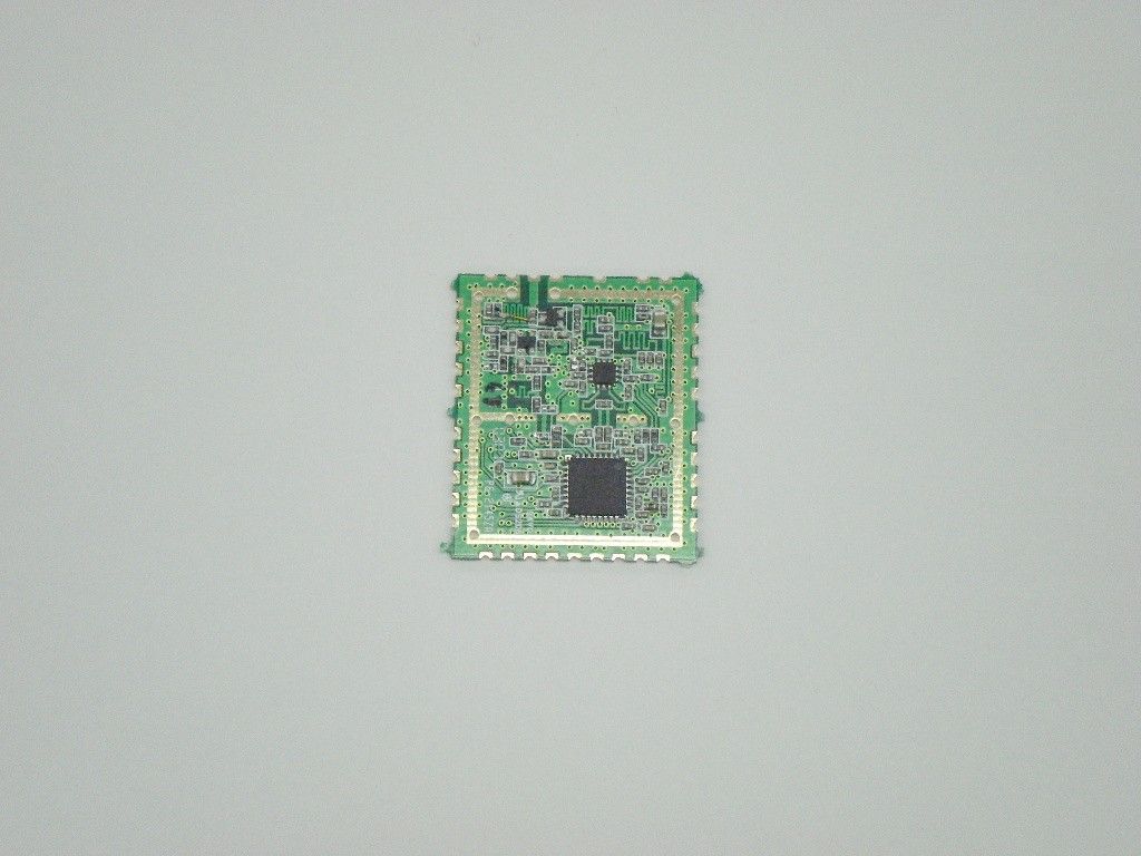
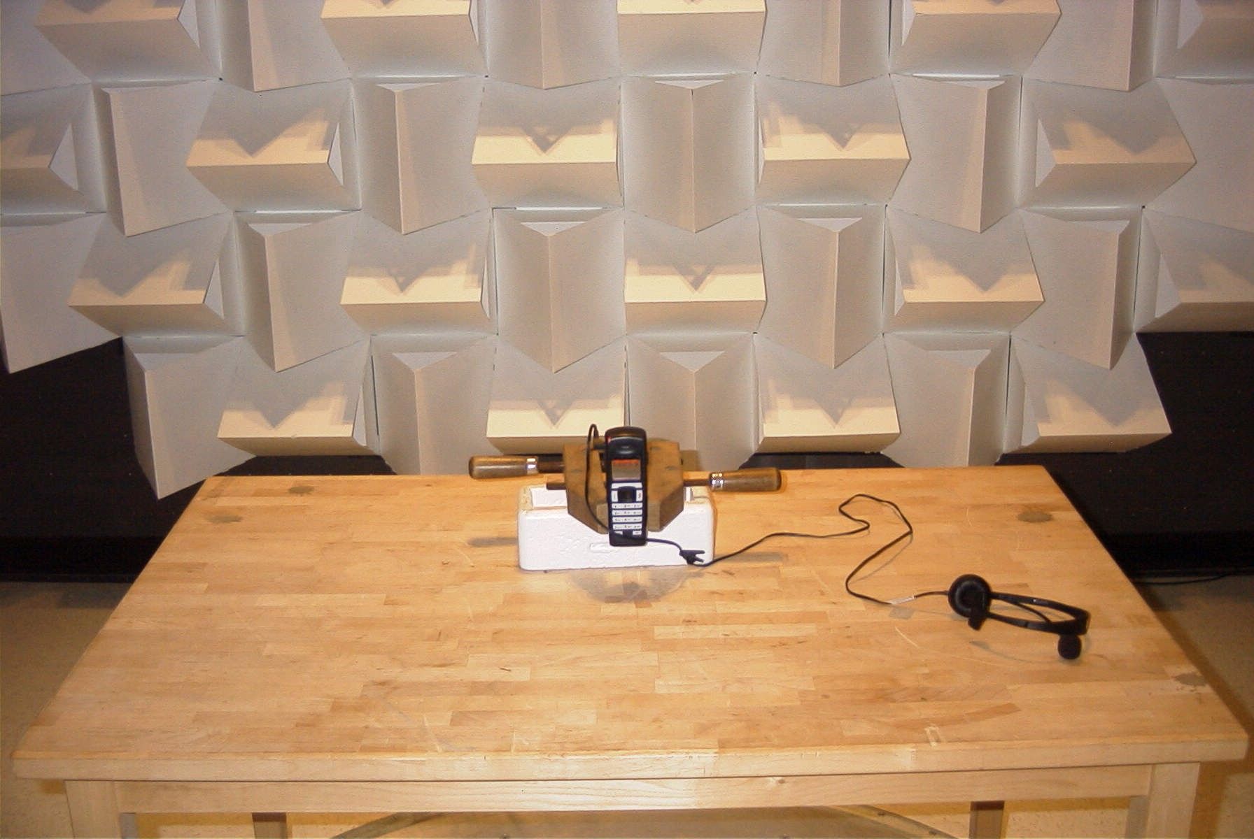
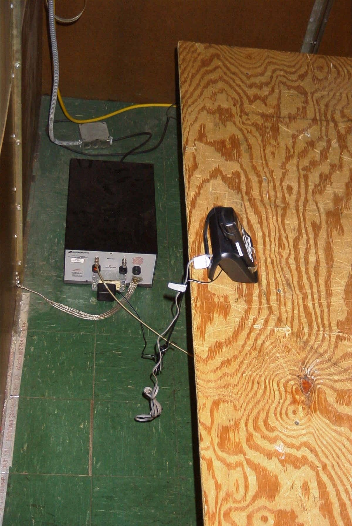
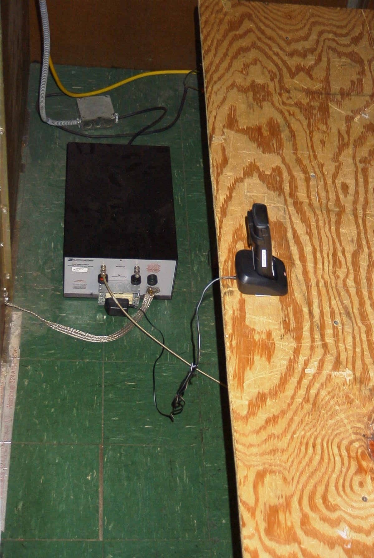
Document Text
Text extracted from the exhibit documents filed with the FCC. Open a document above to read the original.
Users Manual
WelcomeThank you for purchasing a Uniden Multi-Handsetphone.Note: Illustrations in this manual are used forexplanation purposes. Some illustrations in thismanual may differ from the actual unit.AccessibilityUniden provides a customer service hotline foraccessibility questions. If you have a disability andneed customer service assistance or if you haveany questions about how Uniden’s products canaccommodate persons with disabilities, please callthe accessibility voice/TTY line: 1-800-874-9314. A representative is available to talk to you M-F,8:00 am to 5:00 pm, CST. After hours, you canleave us a message, and we will call you back.Information is also available on our website, www.uniden.com, under the “Accessibility” link. Introducing your Digital Cordless Telephone• Crystal clear digital sound quality• Caller ID* to see who’s calling before you pick up the phone • 30 Number Caller ID• 100 Phonebook entries• Last 10 number redial• 10 handset ringer options (6 Melodies and 4 Tones) • Room monitor**• Sound enhancer lets you adjust the tone of your earpiece to your personal preference. • Integrated telephone answering machine (DECT180/DECT180-2 only) * Feature requires Caller ID service from your local telephone company. There is usually a feefor this service. ** Multiple handset are required for these features.In this guide you will find all the information youneed, explained simply to help you get the mostfrom your phone.IMPORTANTThis equipment is not designed for makingemergency calls when the power fails. Alternativearrangements should be made for access toemergency services. [1] UC504DH(DECT160-2) OM 8/17/06 3:37 PM Page 1 Setting up 4 Finding a location 4 Connecting your phone 4 Preparing the handsets 5 Installing and charging the handset battery pack 5 Battery Low Warning 6 Battery Performance 6 Setting the date and time 6 Connecting the telephone line cord 6 Your handset 7 Your base 8 Your handset display 9 Standby Display 10 Quick Guide 11 Using your phone 12 Make a call 12 Adjust the earpiece/speaker volume during a call 12 Make a call by pre-dialing 12 Handset range 12 Call timer 12 Handsfree 12End a call 13 Receive a call 13 Call Waiting 13 Receiving internal calls 13 Muting the ringer 13 Redial 14 Redial the last number called 14 Redial any of the last 10 numbers called 14 Store a redial number to the phonebook 14 Deleting numbers from the redial list 15 Mute (privacy) 15 Finding/paging handsets 15 Keypad lock 16 Conversation recording(DECT180/DECT180-2 only) 16 Using the phonebook 17 Store a phonebook name/number 17 View and dial a phonebook entry 18 Edit a phonebook name/number 18 Delete a phonebook name/number 19 Copy phonebook names/numbers 19 Check available memory space 19 Handset and base menu settings 20 Handset ringer volume 20 Handset ringer type 20 Auto talk 21 Sound enhancer 21 Appointment 21 Alarm 22 Handset name 22 Talk display 22 Language 23 Base ringer volume (DECT180/DECT180-2 only) 23 Base ringer type (DECT180/DECT180-2 only) 24 Prefix dialing 24 Seven-Digit Dialing 25 Call barring 25 [2] Contents UC504DH(DECT160-2) OM 8/17/06 3:37 PM Page 2 [3] Settings menu 26 Tones 26 Dial Mode 26 Tone Dialing Switch-Over 27 Registering a new handset 27 De-register a handset or a base 28 Base PIN code 29 Selecting a base 29 Resetting your phone 30 Default settings 31 Network services 32 Caller ID 32 Call Waiting Tone 32 Calls log 32 View the Calls log 33 Copy Calls log number to the phonebook 33 Delete Calls log entry(ies) 34 Message waiting (DECT160/DECT160-2 only) 34 Using extra handsets 35 Room monitor 35 Using room monitor 35 Call another handset (internal or intercom call) 36 Answer an external call while on an internal call 36 Transferring a call 36 Conference call 37 The Telephone Answering Machine(DECT180/DECT180-2 only) 38 Answering Machine Operation from a Handset 38 Message Playback 38 Record Memo 38 Answering Machine Settings 38 Answer on/off 39 Play/Delete/Record OGM 39 Select OGM 39 Setting Call Screen 39 Using Call Screen 39 Ring Delay 40 Message Length 40 Setting Remote PIN 40 Message Alert 40 Language 40 Using the Base Answering Machine 41 Remote Access Away from Home 42 Simple solutions 43 Handset/Base 43 Caller ID 44 Telephone Answering Machine(DECT180/DECT180-2 only) 44 General information 45 Specifications 45 Maintenance 45 Cleaning your product 45 Replacing the handset battery pack 45 Liquid Damage 46 Precautions 47 I.C. Notice 50 Warranty 51 UC504DH(DECT160-2) OM 8/17/06 3:37 PM Page 3 Setting upFollow these simple steps to prepare yourphone for use.Finding a location• The location should be close to both a phone jack and a continuous power outlet (one whichis not connected to a switch). • The base and handset should be kept away from sources of electrical noise such as motors,microwave ovens, and fluorescent lighting. • For better reception, place the base as high as possible. • The base should be placed in an open area for optimum range and reception. • If your home has wired alarm equipment connected to a phone line, be sure thatinstalling the system does not disable youralarm equipment. If you have questions aboutwhat will disable alarm equipment, contact yourtelephone company or a qualified installer. Connecting your phone1 Connect the base power supply to the back of the base. Plug the other end into the wallelectrical outlet.WARNINGUse only the power supply that came with your phone.Using another power supply could seriously damage your phone and invalidate your warranty.Do not connect the telephone line cord until your handset is fully charged. This will prevent the risk of the phone being answered before thebattery pack is charged. Answering the phone before the battery pack is fully charged mayprevent them from reaching their optimumcapacity. 2 If you have purchased a model containing multiple handsets and chargers, connect eachcharger's power supply to the charger base andplug into a wall electrical outlet. [4] UC504DH(DECT160-2) OM 8/17/06 …
Text truncated - open the document above for the full version.
Cover Letter(s)
REQUEST FOR CONFIDENTIALITY April 13, 2007 To: Federal Communications Commission Equipment Authorization Branch, Lab Div., OET 7435 Oakland Mills Road Columbia, Maryland 21046 Subject: Data for FCC Certification Applicant: Uniden America Corporation 181 N. Country Club Road, P.O. Box 580 Lake City, South Carolina 29560 James R. Haynes, Vice President, Engineering and Regulatory Affairs TYPE OF EQUIPMENT: 1.9 GHz UPCS Cordless Telephone FCC IDENTIFIERS: AMWUC511 and AMWUU644 Dear Sir or Madam: Some of the material included in this application contains trade secrets and proprietary information not customarily released to the public. Because public disclosure of the material might be harmful to the applicant and provide unjustified benefits to its competitors, it is requested that the following be withheld from public disclosure: Operational Spec - file: AMWUC511-UU644 Operational Specification.pdf Circuit Description - file: AMWUC511_CIRCUIT DESCRIPTION.pdf Schematic Diagram - file: AMWUC511_SCHEMATIC.pdf Block Diagram - file: AMWUC511_BASE_BLOCK.pdf Trade secrets and proprietary information can be held confidential. Therefore, we wish to invoke the act under the provisions of 47CFR, Sections 0.457(d) and 0.459. Please contact the undersigned if you have any questions or need any further information. Regards, James R. Haynes Vice President, Engineering and Regulatory Affairs
ID Label/Location Info
Equipment Identification Label Equipment Labels: The following Label is permanently affixed to the equipment. 1) HANDSET: 23 mm (W) X 15 mm (H) DECT2080
RF Exposure Info
Company: Uniden America Corporation FCC ID: AMWUU644 IC ID: 513C-UC511 Model(s): DECT2080 DUT: Portable UPCS/LE-PCS DECT Handset 1921.536 - 1928.448 MHz 2007 Celltech Labs Inc. This document is not to be reproduced in whole or in part without the prior written permission of Celltech Labs Inc. Page 1 of 45 Date(s) of Evaluation March 20, 2007 Test Report Serial No. 031907AMW -T822-S15T Report Revision No. Revision 1.1 Report Issue Date March 26, 2007 Description of Test(s) Specific Absorption Rate RF Exposure Category General Population Certificate No. 2470.01 R R F F E E X X P P O O S S U U R R E E E E V V A A L L U U A A T T I I O O N N S S P P E E C C I I F F I I C C A A B B S S O O R R P P T T I I O O N N R R A A T T E E S S S A A A R R R T T T E E E S S S T T T R R R E E E P P P O O O R R R T T T FOR UNIDEN AMERICA CORPORATION 1.9 GHz UPCS/LE-PCS DECT PORTABLE HANDSET MODEL(S): DECT2080 Test Report Serial No. 031907AMW-T822-S15T Test Report Revision No. Revision 1.1 (FCC ID Correction) Revision 1.0 (Initial Release) Test Lab and Location Celltech Compliance Testing & Engineering Lab (Celltech Labs Incorporated) 1955 Moss Court Kelowna, BC Canada V1Y 9L3 FCC ID: AMWUU644 IDENTIFIERS IC ID: 513C-UC511 TEST STANDARD(S) & PROCEDURE(S) APPLIED FCC OET Bulletin 65, Supplement C (01-01) Industry Canada RSS-102 Issue 2 IEEE 1528-2003 Certificate No. 2470.01 Test Report Prepared By: Cheri Frangiadakis Test Report Writer Celltech Labs Inc. Test Report Reviewed By: Jonathan Hughes General Manager Celltech Labs Inc. Company: Uniden America Corporation FCC ID: AMWUU644 IC ID: 513C-UC511 Model(s): DECT2080 DUT: Portable UPCS/LE-PCS DECT Handset 1921.536 - 1928.448 MHz 2007 Celltech Labs Inc. This document is not to be reproduced in whole or in part without the prior written permission of Celltech Labs Inc. Page 2 of 45 Date(s) of Evaluation March 20, 2007 Test Report Serial No. 031907AMW -T822-S15T Report Revision No. Revision 1.1 Report Issue Date March 26, 2007 Description of Test(s) Specific Absorption Rate RF Exposure Category General Population Certificate No. 2470.01 DECLARATION OF COMPLIANCE SAR RF EXPOSURE EVALUATION Test Lab and Location CELLTECH LABS INCORPORATED Testing and Engineering Services 1955 Moss Court Kelowna, BC V1Y 9L3 Canada Phone: 250-448-7047 Fax: 250-448-7046 e-mail: [email protected] web site: www.celltechlabs.com Company Information UNIDEN AMERICA CORPORATION Engineering Services Office 181 N. Country Club Road Lake City, SC 29560 United States FCC IDENTIFIER: AMWUU644 IC IDENTIFIER: 513C-UC511 Device Model(s): DECT2080 Rule Part(s) Applied: FCC 47 CFR §2.1093; Health Canada Safety Code 6 Test Procedure(s) Applied: FCC OET Bulletin 65, Supplement C (Edition 01-01) Industry Canada RSS-102 Issue 2 IEEE Standard 1525-2003 Device Classification(s): FCC Part 15 Unlicensed PCS portable Tx held to ear (PUE) IC 2 GHz Licence Exempt Personal Communications Service Device (LE-PCS) Device Description: 1.9 GHz UPCS/LE-PCS DECT Portable Handset Transmit Frequency Range: 1921.536 - 1928.448 MHz Mode of Operation: TDD (Time Division Duplexing) Modulation Type: FSK (Frequency Shift Keying) Max. Reference Power Level Measured: 17.64 dBm (58.1 mW) EIRP (1924.992 MHz) Max. Source-Based Time-Av. Duty Cycle: 4 % (Crest Factor: 1:25) Max. Source-Based Time-Av. Power Level: 3.66 dBm (2.32 mW) EIRP (1924.992 MHz) Antenna Type(s) Tested: Internal Battery Type(s) Tested: NiMH 2.4 V, 650 mAh Body-worn Accessories Tested: Plastic Belt-Clip (7 mm spacing) Audio Accessories Tested: Headset (Ear-Loop with Boom-Microphone P/N: ZA-133) Max. SAR Level(s) Evaluated: Head: 0.0204 W/kg (1g average) Body: 0.0125 W/kg (1g average) Celltech Labs Inc. declares under its sole responsibility that this wireless portable device is compliant with the Specific Absorption Rate (SAR) RF exposure requirements specified in FCC 47 CFR §2.1093 and Health Canada’s Safety Code 6. The device was tested in accordance with the measurement standards and procedures specified in FCC OET Bulletin 65, Supplement C (Edition 01-01), Industry Canada RSS-102 Issue 2 and IEEE Standard 1528-2003 for the General Population / Uncontrolled Exposure environment. All measurements were performed in accordance with the SAR system manufacturer recommendations. I attest to the accuracy of data. All measurements were performed by me or were made under my supervision and are correct to the best of my knowledge and belief. I assume full responsibility for the completeness of these measurements and vouch for the qualifications of all persons taking them. This test report shall not be reproduced partially, or in full, without the prior written approval of Celltech Labs Inc. The results and statements contained in this report pertain only to the device(s) evaluated. Test Report Approved By: Sean Johnston SAR Lab Manager Celltech Labs Inc. Company: Uniden America Corporation FCC ID: AMWUU644 IC ID: 513C-UC511 Model(s): DECT2080 DUT: Portable UPCS/LE-PCS DECT Handset 1921.536 - 1928.448 MHz 2007 Celltech Labs Inc. This document is not to be reproduced in whole or in part without the prior written permission of Celltech Labs Inc. Page 3 of 45 Date(s) of Evaluation March 20, 2007 Test Report Serial No. 031907AMW -T822-S15T Report Revision No. Revision 1.1 Report Issue Date March 26, 2007 Description of Test(s) Specific Absorption Rate RF Exposure Category General Population Certificate No. 2470.01 TABLE OF CONTENTS 1.0 INTRODUCTION ___________________________________________________________________ 4 2.0 DESCRIPTION OF DEVICE UNDER TEST (DUT)_________________________________________ 4 3.0 SAR MEASUREMENT SYSTEM ______________________________________________________ 5 4.0 MEASUREMENT SUMMARY _________________________________________________________ 6 MEASUREMENT SUMMARY (CONT.) _____________________________________________________ 7 5.0 DETAILS OF SAR EVALUATION______________________________________________________ 8 DETAILS OF SAR EVALUATION (CONT.) __…
Text truncated - open the document above for the full version.
Test Report
________________________________ ________________________________ TEST REPORT STANDARD (s): FCC Part 15, Subparts B, C, and D IC RSS-213 & ICES-003 UPCS / LE-PCS Isochronous Device Base & Handset: 1921.536 – 1928.448 MHz ANSI C63.17 - 1998 (or 2005 Draft where applicable) ANSI C63.4 – 2003 APPLICANT: UNIDEN AMERICA CORPORATION 181 N. COUNTRY CLUB RD. / P. O. BOX 580 LAKE CITY SC 29560 MODEL NUMBER: DCX200 (Handset) DECT2080 (Base) DESCRIPTION OF PRODUCT: 1.9 GHz UPCS/LE-PCS DECT Cordless Telephone FCC IDs: AMWUU644 (Handset) AMWUC511 (Base) IC: 513C-UC511 DATE SAMPLE RECEIVED FOR TESTING: 3/22/2007 DATE TESTED: 4/17/2007 TEST RESULTS: PASS FAIL 849 NW State Road 45 PO Box 370 Newberry, FL 32669 APPLICANT: UNIDEN AMERICA CORPORATION FCC ID: AMWUU644; AMWUC511 MODEL #: DCX200, AMWUC511 REPORT #: U\UNIDEN AMW\683AUT7\683AUT7TestReport.doc PAGE 2 of 28 PLEASE NOTE: THE ATTACHED REPORT SHALL NOT BE REPRODUCED EXCEPT IN FULL WITHOUT THE WRITTEN APPROVAL OF TIMCO ENGINEERING, INC. TABLE OF CONTENTS 1 GENERAL INFORMATION .............................................................................3 1.1 COMPLIANCE STATEMENT: ...............................................................3 1.2 EQUIPMENT UNDER TEST SPECIFICATION .......................................4 1.2.1 TRANSMITTER TECHNICAL CHARACTERISTICS ............4 2 TEST STANDARDS .......................................................................................5 3 TEST ENVIRONEMENT................................................................................. 5 4 TEST RESULTS ............................................................................................6 4.1 RADIATED PEAK TRANSMIT POWER..................................................6 4.1.1 BASE: ............................................................................ 7 4.1.2 HANDSET: ..................................................................... 7 4.2 TRANSMITTER SPURIOUS EMISSIONS ..............................................8 4.2.1 BASE: ............................................................................ 8 4.2.2 HANDSET: ..................................................................... 9 4.3 GENERAL RADIATED SPURIOUS EMISSIONS ....................................10 4.3.1 RADIATED SPURIOUS EMISSIONS ................................10 4.3.2 BASE in STAND-BY MODE:............................................11 4.3.3 HANDSET IN STAND-BY MODE: ....................................12 4.3.4 AC POWER LINES CONDUCTED SPURIOUS EMISSIONS: 13 4.3.5 TEST EQUIPMENT AND ANCILLARIES USED FOR TESTS 22 4.3.6 TEST SETUP PHOTOGRAPHS.........................................23 5 EUT EXTERNAL PHOTOGRAPHS .................................................................. 28 6 EUT INTERNAL PHOTOGRAPHS ................................................................... 28 7 LABEL PHOTOGRAPHS ................................................................................ 28 APPLICANT: UNIDEN AMERICA CORPORATION FCC ID: AMWUU644; AMWUC511 MODEL #: DCX200, AMWUC511 REPORT #: U\UNIDEN AMW\683AUT7\683AUT7TestReport.doc PAGE 3 of 28 1 GENERAL INFORMATION The test results relate only to the items tested. 1.1 COMPLIANCE STATEMENT: This equipment has been tested in accordance with the standards identified in this test report. To the best of my knowledge and belief, these tests were performed using the measurement procedures described in this report and demonstrate that the equipment complies with the appropriate standards. No modifications were made to the equipment during testing in order to demonstrate compliance with these standards. I attest that the necessary measurements were made, under my supervision, at TIMCO ENGINEERING, INC. located at 849 N.W. State Road 45, Newberry, Florida 32669. Authorized Signatory Name: Mario de Aranzeta Signature: < Mario de Aranzeta > Function: Engineer Date: 4/20/07 Test engineer name: Nam Nguyen Signature: <ON FILE> Date: 4/17/2007 APPLICANT: UNIDEN AMERICA CORPORATION FCC ID: AMWUU644; AMWUC511 MODEL #: DCX200, AMWUC511 REPORT #: U\UNIDEN AMW\683AUT7\683AUT7TestReport.doc PAGE 4 of 28 1.2 EQUIPMENT UNDER TEST SPECIFICATION Characterization of test item: Prototype Pre-production Production Construction of equipment: Single unit Multiple units (If multiple units describe each one clearly) TYPE OF EQUIPMENT: Fixed Mobile Portable Station X Transmitter Simplex X Integral antenna (Handset and Base) Receiver X Duplex Single antenna connector Transceiver Two antenna connector X Battery charger Vehicle battery adaptor Remote Control Head 1.2.1 TRANSMITTER TECHNICAL CHARACTERISTICS MAXIMUM RATED TRANSMITTER OUTPUT POWER: 70mW ERP for the Base and 72mW ERP for the Handset. APPLICANT: UNIDEN AMERICA CORPORATION FCC ID: AMWUU644; AMWUC511 MODEL #: DCX200, AMWUC511 REPORT #: U\UNIDEN AMW\683AUT7\683AUT7TestReport.doc PAGE 5 of 28 2 TEST STANDARDS FCC Part 15, Subparts B, C, and D IC RSS-213 & ICES-003 UPCS / LE-PCS Isochronous Device Base & Handset: 1921.536 – 1928.448 MHz ANSI C63.17 - 1998 (or 2005 Draft where applicable) ANSI C63.4 - 2003 3 TEST ENVIRONEMENT Temperature Normal test temperature (Tnom): 22 °C Extreme test temperatures (Tmax): n/a °C (Tmin): n/a °C Relative Humidity 50 % Details of power supply Normal test voltage Handset (Vnom): 2.4 VDC Base (Vnom): 9 VDC (from adapter) APPLICANT: UNIDEN AMERICA CORPORATION FCC ID: AMWUU644; AMWUC511 MODEL #: DCX200, AMWUC511 REPORT #: U\UNIDEN AMW\683AUT7\683AUT7TestReport.doc PAGE 6 of 28 4 TEST RESULTS 4.1 RADIATED PEAK TRANSMIT POWER Clause: 15.319 (c) Test procedure: ANSI C63.17 section 6.1.2 Technical requirements/Limits: The peak transmit power shall not exceed 100 μW multiplied by the square root of the emission bandwidth in hertz measured at 26dBc. The measured emissions bandwidth is 1.5 MHz max Limit = 100μW * √(BW in Hz)= 0.122W = 20.8 dBm and Radiated limit ≤ 118 dBμV/m at 3m by radiated measurement derived from Friis formula as follows P = (E*d) 2 /30G, where P = 0.122 W = 20.8 dB…
Text truncated - open the document above for the full version.
Test Report
1) if applicable rev. 1.4 UPCS_DECTbased_ICS_CLIP_BASE.doc page 1 (6) -ETS- Dr. Genz GmbH, Germany Storkower Straße 38c D-15526 Reichenwalde b. Berlin Telephone: +49.33631.888.00 Fax: +49.33631.888.640 ELECTRONIC TECHNOLOGY SYSTEMS DR.GENZ GMBH UPCS (DECT based) – Implementation Conformance Statement Description : Basestation Model : CLIP Basestation Use : FP PP Repeater System Type HW version WORKING STAGE SW version Ver. 0.02 RFPI / PIN Decl. emission BW 1.4MHz Decl. lower threshold DUT Decl.upper threshold 1) -62.4 dBm Product information Standard: FCC part 15D other: Frequency band: 1920 – 1930 MHz other: Number of RF channels: 5 Number of logical channels: 60 (time and spectrum windows) Used slot type: single double Used slot(s): even odd For doubleslot connection even and odd slots are used Operating mode: simplex duplex other: 1) if applicable rev. 1.4 UPCS_DECTbased_ICS_CLIP_BASE.doc page 2 (6) -ETS- Dr. Genz GmbH, Germany Storkower Straße 38c D-15526 Reichenwalde b. Berlin Telephone: +49.33631.888.00 Fax: +49.33631.888.640 ELECTRONIC TECHNOLOGY SYSTEMS DR.GENZ GMBH Antennas: Antenna Type Gain [dBi] internal external 1 PCB < 3 2 Metal < 3 3 FP: Do Tx and Rx use the same antenna(s)?: Yes No Antenna Type Gain [dBi] internal external 1 2 3 PP: Do Tx and Rx use the same antenna(s)?: Yes No Antenna diversity: 1) Diversity supported Antenna Tx Rx 1 2 FP 3 1 2 Product information PP 3 1) if applicable rev. 1.4 UPCS_DECTbased_ICS_CLIP_BASE.doc page 3 (6) -ETS- Dr. Genz GmbH, Germany Storkower Straße 38c D-15526 Reichenwalde b. Berlin Telephone: +49.33631.888.00 Fax: +49.33631.888.640 ELECTRONIC TECHNOLOGY SYSTEMS DR.GENZ GMBH Supply and supported temperature ranges (Manufacturer declaration): FP PP Repeater U normal [V] 6.0V U min [V] 5.0V U max [V] 9.0V T min [°C] +10 T max [°C] +40 Power Source Type Manufacturer FP or WRS AC/DC Wall Adaptor ?? PP (charger) Data connection: PSTN other Used radio module 1) : Type : Manufacturer : Ancillary equipment 1) : Description : Type : Manufacturer : Product information Host device 1) : Description : Type : Manufacturer : 1) if applicable rev. 1.4 UPCS_DECTbased_ICS_CLIP_BASE.doc page 4 (6) -ETS- Dr. Genz GmbH, Germany Storkower Straße 38c D-15526 Reichenwalde b. Berlin Telephone: +49.33631.888.00 Fax: +49.33631.888.640 ELECTRONIC TECHNOLOGY SYSTEMS DR.GENZ GMBH Control software 1) : Name : Version : Manufacturer : Product information Additional remarks: 1) if applicable rev. 1.4 UPCS_DECTbased_ICS_CLIP_BASE.doc page 5 (6) -ETS- Dr. Genz GmbH, Germany Storkower Straße 38c D-15526 Reichenwalde b. Berlin Telephone: +49.33631.888.00 Fax: +49.33631.888.640 ELECTRONIC TECHNOLOGY SYSTEMS DR.GENZ GMBH FCC 15.323 (c) (5): This device or group of co-operating devices located within 1 meter of each other shall not during any frame period occupy more than 6 MHz of aggregate bandwidth, or alternatively more than one third of the time and spectrum windows defined by the system. Manufacturer agrees: Yes No FCC 15.323 (c) (12): This device shall not use the provisions of (c) (10) or (c) (11) to extend the range of spectrum occupied over space or time for the purpose of denying fair access to spectrum to other devices. Manufacturer agrees: Yes No FCC 15.307 (b): The applicant is a participating member of UTAM, Inc. and will provide a related affidavit from UTAM, Inc. in course of certification. Confirmation by applicant: Yes No FCC 15.319 (f) Automatic discontinuation of transmission: This device shall automatically discontinue transmission in case of either absence of information to transmit or operational failure. Automatic break off the transmissions means break off of connection and break of transmissions which are not control and signalling information or repetitive codes of complete frame or burst intervals. In case of devices using basics of DECT technology at least fixed parts and repeaters are using control and signalling information without direct connection to their remote station. Please fill in the table below with the reaction of the EUT (FP and/or PP) using A, B or C. Reaction of EUT Situation FP Verdict 1 Switch-off counter part B 2 Hook-on by counter part B 3 Switch-off by EUT A 4 Hook-on at EUT side Not possible 5 Remove power from EUT A 6 Remove power from counterpart B Manufacturer declarations A – Connection break down, cease of transmit B – Connection break down, EUT transmits signalling information C – Connection break down, counter part transmits signalling information 1) if applicable rev. 1.4 UPCS_DECTbased_ICS_CLIP_BASE.doc page 6 (6) -ETS- Dr. Genz GmbH, Germany Storkower Straße 38c D-15526 Reichenwalde b. Berlin Telephone: +49.33631.888.00 Fax: +49.33631.888.640 ELECTRONIC TECHNOLOGY SYSTEMS DR.GENZ GMBH Supplement Additional remarks: Declared by: Date: 4-11-2006 Name (print): Yoshinobu Fujiwara Signature: Test Summary Requirement FCC Paragraph # IC RSS-213 Paragraph # Required Customer Declaration Test Pass Monitoring time 15.323(c)(1) 4.3.4(b)(1) Monitoring threshold 15.323(c)(2) 4.3.4(b)(2) Maximum transmit period 15.323(c)(3) 4.3.4(b)(3) System acknowledgement 15.323(c)(4) 4.3.4(b)(4) Least Interfered Channel, LIC 15.323(c)(5) 4.3.4(b)(5) Random waiting 15.323(c)(6) 4.3.4(b)(6) Monitoring bandwidth and reaction time 15.323(c)(7) 4.3.4(b)(7) Monitoring antenna 15.323(c)(8) 4.3.4(b)(8) Monitoring threshold relaxation 15.323(c)(9) 4.3.4(b)(9) Duplex system LBT 15.323(c)(10) 4.3.4(b)(10) Co-located device LBT 15.323(c)(11) 4.3.4(b)(11) Fair access 15.323(c)(12) 4.3.4(b)(12) Requirement FCC Paragraph # Required Customer Declaration Test Pass Coordination with fixed microwave 15.307(b) Cross reference 15.309(b) Labeling requirements 15.311, 15.19(a)(3) Power line conducted emissions 15.315, 15.207 Antenna requirement 15.315, 15.203 Digital modulation techniques 15.319(b) Peak transmit power 15.319(c) Power spectral density 15.319(d) Antenna Gain 15.319(e) Automatic discontinuation of transmission 15.319(f) Safety exposure levels 15.319(i…
Text truncated - open the document above for the full version.
Contact Information
Applicant
Paul Roby
Test Firm
Timco Engineering, Inc.S Sanders
Technical Specifications
| # | Rule Parts | Frequency Range | Power Output |
|---|---|---|---|
| 1 | 15D | 1.92 GHz - 1.93 GHz | 72.00 mW |
Other Applications from Uniden America Corporation
AMWUA2405
Apr 15, 2026RADAR DETECTOR
Equipment Class
JBP - Part 15 Class B Computing Device PeripheralAMWUA2406
Apr 15, 2026RADAR DETECTOR
Equipment Class
JBP - Part 15 Class B Computing Device PeripheralAMWUA2402
Jul 23, 2024RADAR DETECTOR
Equipment Class
CRD - Part 15 Radar Detector
AMWUA2404
Feb 17, 2024Wi-Fi Bluetooth Combo Module
Equipment Class
DTS - Digital Transmission System
AMWUA2301
Feb 15, 2023RADAR DETECTOR
Equipment Class
CRD - Part 15 Radar Detector