APYHRO000301900MHz GSM/GPRS Cellular Phone
Sharp Corporation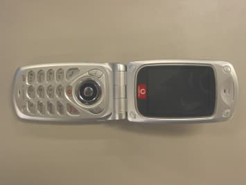
Click to zoom
Application Details
- Equipment Class
- PCE - PCS Licensed Transmitter held to ear
- Date of Grant
- May 04, 2003
- Application Purpose
- Original Equipment
- Date of Application
- May 04, 2003
- Equipment Note
- 1900MHz GSM/GPRS Cellular Phone
- Frequency Range
- 1850.20000000 - 1909.80000000
- Company
- Sharp Corporation
- Country
- Japan
Documents & Files
Document Text
Text extracted from the exhibit documents filed with the FCC. Open a document above to read the original.
Users Manual
7Your Phone Your Phone Please check the following carefully. Your phone should come complete with: • GSM 900/1800/1900 GPRS phone • Rechargeable Li-ion battery • AC charger • Hands free • User guide Accessories • Li-ion spare battery (XN-1BT11) • Cigarette lighter charger (XN-1CL10) • Car holder (XN-1CH11) • Data cable (RS232C cable: XN-1DC10) Some of the above accessories may not be offered by region. For details, please contact your dealer. (option) Getting Started8 Getting Started 22 23 24 25 26 1 2 3 4 5 6 7 16 8 9 10 11 12 13 14 15 17 18 19 20 21 9Getting Started 1. Earpiece 2. Navigation Keys (Arrow Keys): Move the cursor to select menu items, etc. Up/Down arrow keys: Search the Phonebook entries in stand-by mode. Left arrow key:Starts the Saved Picture in stand-by mode. Right arrow key:Displays the Phonebook menu or the list of Saved Pictures in stand-by mode. 3. Centre Key:Displays the Main Menu and executes the functions. in this manual indicates this key. 4. Left Soft Key:Executes the function at the bottom left on the screen. 5. Send Key:Makes or accepts calls, views the call in stand-by mode. 6. Voice Mail Key:Used to connect to Voice mail centre. (Depends on the SIM card.) 7. * /Shift Key, Finder Switch Key: Enters * or switch the text mode. Switches finders between main display and external display. Press and hold this key to switch input modes among three modes: Abc, ABC, abc and 123. 8. Main display 9. Hands free Connector 10. Right Soft Key:Executes the function at the bottom right on the screen. 11. “Vodafone live” Key: Used to access the “Vodafone live!” by opening the browser. 12. End/Power Key:Ends a call, turns power on/ off. 13. Keypad Getting Started10 14. #/Flash Light Key: Switches symbol screens. Press and hold this key to shift text input mode between Normal and T9 mode. Turns the flash on or off in Camera mode. 15. Microphone 16. External Connector:Used to connect either the charger or data cable. 17. Aerial 18. Flash light:Used as a flash or an auxiliary light in still camera/movie camera mode, for a battery charge indicator, or notification for incoming calls, data/fax calls or text messages. 19. Camera 20. Macro Dial:Turns the dial to normal () or macro () position. 21. External Display 22. Infrared Port:Sends and receives data via infrared. 23. Speaker 24. RF Connector 25. Side-Up/Side-Down Keys: Move the cursor to select menu items, adjust the earpiece volume, etc. 26. Battery Cover 11Getting Started Inserting the SIM Card and the Battery 1.Slide off the battery cover. 2.Slide the SIM card into the SIM holder. SIM card Getting Started12 3.Hold the battery so that the metal contacts of the battery are facing down, slide the guides on the top of the battery into the battery slots , and then insert it . 4.Replace the battery cover as shown below and slide it as shown. Note • Make sure that only 3V SIM cards are used. • Use only the approved battery (XN-1BT11). 13Getting Started Removing the SIM Card and the Battery 1.Make sure to turn off your phone and disconnect charger and other accessories. Slide off the battery cover. 2.Pick up the battery using the protruding edge and remove the battery from the phone. 3.Slide the SIM card by pushing the back of the card and remove it from the SIM holder. Getting Started14 Battery Disposal The device is supported by a battery. In order to protect the environment, please read the following points concerning battery disposal: • Take the used battery to your local waste depot, dealer or customer service centre for recycling. • Do not expose the used battery to an open flame, into water or dispose with the household waste. Charging the Battery You must charge the battery for at least 2 hours before using your phone for the first time. To Charge Using the Charger 1.Connect the charger to the external socket located at the bottom of the phone with the charger’s “PUSH TOP” mark facing towards you, and to an AC outlet. The flash light flashes red. Standard charging time: Approx. 2 hours. Flash light 15Getting Started Note • Charging time may be longer than above depending on the state of a battery and a surrounding situation. (See “Battery” on page 176.) To disconnect the charger Push and hold the side buttons of the charger, then disconnect the charger from the external socket of the phone. 2.When charging is complete, the flash light turns off. Unplug the charger from the AC outlet, then unplug the charger connector from the phone. Note • Do not use any non approved charger, this may damage your phone and invalidate any warranty, please see “Battery” on page 176 for details. • When the phone is charging, the animated battery status icon () will be displayed in the upper right of the screen. To Charge Using the Cigarette Lighter Charger The cigarette lighter charger (option) supplies power for charging from the cigarette lighter socket of a car. Battery Level Indicator The current battery level is displayed in the upper right hand side of the main display and the external display. Low Battery During Use When the battery is running low, an alarm will sound and the “” will appear on the main display and the external display. If you are using your phone and you hear the “low battery” alarm, attach your charger as soon as possible. The phone may not be able to continue normal operation if you continue to use it. The battery may only last five minutes before the phone itself powers down during a call. Charge LevelIndicators Full level (greater than 60%) Partial level (less than 60%) Partial level (less than 30%) Low level (less than 10%) Charging the battery is recommended. Empty Charge the battery. Getting Started16 Turning Your Phone On and Off To turn the power on, press and hold F for approximately 2 seconds. The stand-by screen appears. To turn the power off, press and hold F for approximately 2 seconds. Entering the PIN Code If activated you will be asked to enter a PIN (Personal Identification Number) code after turning on…
Text truncated - open the document above for the full version.
ID Label/Location Info
FCC ID Label & FCC ID Label Placement Location
Operational Description
7Your Phone Your Phone Please check the following carefully. Your phone should come complete with: • GSM 900/1800/1900 GPRS phone • Rechargeable Li-ion battery • AC charger • Hands free • User guide Accessories • Li-ion spare battery (XN-1BT11) • Cigarette lighter charger (XN-1CL10) • Car holder (XN-1CH11) • Data cable (RS232C cable: XN-1DC10) Some of the above accessories may not be offered by region. For details, please contact your dealer. (option) Getting Started8 Getting Started 22 23 24 25 26 1 2 3 4 5 6 7 16 8 9 10 11 12 13 14 15 17 18 19 20 21 9Getting Started 1. Earpiece 2. Navigation Keys (Arrow Keys): Move the cursor to select menu items, etc. Up/Down arrow keys: Search the Phonebook entries in stand-by mode. Left arrow key:Starts the Saved Picture in stand-by mode. Right arrow key:Displays the Phonebook menu or the list of Saved Pictures in stand-by mode. 3. Centre Key:Displays the Main Menu and executes the functions. in this manual indicates this key. 4. Left Soft Key:Executes the function at the bottom left on the screen. 5. Send Key:Makes or accepts calls, views the call in stand-by mode. 6. Voice Mail Key:Used to connect to Voice mail centre. (Depends on the SIM card.) 7. * /Shift Key, Finder Switch Key: Enters * or switch the text mode. Switches finders between main display and external display. Press and hold this key to switch input modes among three modes: Abc, ABC, abc and 123. 8. Main display 9. Hands free Connector 10. Right Soft Key:Executes the function at the bottom right on the screen. 11. “Vodafone live” Key: Used to access the “Vodafone live!” by opening the browser. 12. End/Power Key:Ends a call, turns power on/ off. 13. Keypad Getting Started10 14. #/Flash Light Key: Switches symbol screens. Press and hold this key to shift text input mode between Normal and T9 mode. Turns the flash on or off in Camera mode. 15. Microphone 16. External Connector:Used to connect either the charger or data cable. 17. Aerial 18. Flash light:Used as a flash or an auxiliary light in still camera/movie camera mode, for a battery charge indicator, or notification for incoming calls, data/fax calls or text messages. 19. Camera 20. Macro Dial:Turns the dial to normal () or macro () position. 21. External Display 22. Infrared Port:Sends and receives data via infrared. 23. Speaker 24. RF Connector 25. Side-Up/Side-Down Keys: Move the cursor to select menu items, adjust the earpiece volume, etc. 26. Battery Cover 11Getting Started Inserting the SIM Card and the Battery 1.Slide off the battery cover. 2.Slide the SIM card into the SIM holder. SIM card Getting Started12 3.Hold the battery so that the metal contacts of the battery are facing down, slide the guides on the top of the battery into the battery slots , and then insert it . 4.Replace the battery cover as shown below and slide it as shown. Note • Make sure that only 3V SIM cards are used. • Use only the approved battery (XN-1BT11). 13Getting Started Removing the SIM Card and the Battery 1.Make sure to turn off your phone and disconnect charger and other accessories. Slide off the battery cover. 2.Pick up the battery using the protruding edge and remove the battery from the phone. 3.Slide the SIM card by pushing the back of the card and remove it from the SIM holder. Getting Started14 Battery Disposal The device is supported by a battery. In order to protect the environment, please read the following points concerning battery disposal: • Take the used battery to your local waste depot, dealer or customer service centre for recycling. • Do not expose the used battery to an open flame, into water or dispose with the household waste. Charging the Battery You must charge the battery for at least 2 hours before using your phone for the first time. To Charge Using the Charger 1.Connect the charger to the external socket located at the bottom of the phone with the charger’s “PUSH TOP” mark facing towards you, and to an AC outlet. The flash light flashes red. Standard charging time: Approx. 2 hours. Flash light 15Getting Started Note • Charging time may be longer than above depending on the state of a battery and a surrounding situation. (See “Battery” on page 176.) To disconnect the charger Push and hold the side buttons of the charger, then disconnect the charger from the external socket of the phone. 2.When charging is complete, the flash light turns off. Unplug the charger from the AC outlet, then unplug the charger connector from the phone. Note • Do not use any non approved charger, this may damage your phone and invalidate any warranty, please see “Battery” on page 176 for details. • When the phone is charging, the animated battery status icon () will be displayed in the upper right of the screen. To Charge Using the Cigarette Lighter Charger The cigarette lighter charger (option) supplies power for charging from the cigarette lighter socket of a car. Battery Level Indicator The current battery level is displayed in the upper right hand side of the main display and the external display. Low Battery During Use When the battery is running low, an alarm will sound and the “” will appear on the main display and the external display. If you are using your phone and you hear the “low battery” alarm, attach your charger as soon as possible. The phone may not be able to continue normal operation if you continue to use it. The battery may only last five minutes before the phone itself powers down during a call. Charge LevelIndicators Full level (greater than 60%) Partial level (less than 60%) Partial level (less than 30%) Low level (less than 10%) Charging the battery is recommended. Empty Charge the battery. Getting Started16 Turning Your Phone On and Off To turn the power on, press and hold F for approximately 2 seconds. The stand-by screen appears. To turn the power off, press and hold F for approximately 2 seconds. Entering the PIN Code If activated you will be asked to enter a PIN (Personal Identification Number) code after turning on…
Text truncated - open the document above for the full version.
RF Exposure Info
in accordance with the requirements of FCC Report and Order: ET Docket 93-62, and OET Bulletin 65 Supplement C for Tri-Bands (GSM/DCS/PCS) Cellular Phone MODEL: GX20 FCC ID: APYHRO00030 April 23, 2003 REPORT NO: 03U1954-1 Prepared for Sharp Corporation Sharp Plaza Mahwah-City New Jersey, 07430 U.S.A Prepared by COMPLIANCE CERTIFICATION SERVICES 561F MONTEREY ROAD, MORGAN HILL, CA 95037, USA TEL: (408) 463-0885 REPORT NO: 03U1954-1 DATE: April 23, 2003 FCC ID: APYHRO00030 COMPLIANCE CERTIFICATION SERVICES Page: 2 of 25 This report shall not be reproduced except in full, without the written approval of CCS. This document may be altered or revised by Compliance Certification Services personnel only, and shall be noted in the revision section of the document. CERTIFICATE OF COMPLIANCE (SAR EVALUATION) DATES OF TEST: April 21-22, 2003 REPORT NO: 03U1954-1 APPLICANT: Sharp Corporation Sharp Plaza Mahwah, New Jersey - 07430 U.S.A MODEL: GX-20 FCC ID: APYHRO00030 DEVICE CATEGORY: PORTABLE DEVICES EXPOSURE CATEGORY: GENERAL POPULATION/UNCONTROLLED EXPOSURE Test Sample is a: Production unit Modulation type: GSM+GPRS Operating Mode: Maximum continuous output Tx Frequency: 1850.2 ~ 1909.8 MHz Max. O/P Power: (Conducted) GSM mode - 29.96 dBm GPRS mode - 29.95 dBm Max. SAR (1g): 0.416 W/Kg (Left head - touched position) 0.232 W/Kg (Body worn – GSM mode) 0.494 W/Kg (Body worn – GPRS mode) Application Type: Certification FCC Rule Part(s): 24 (E) Note: This device contains 900MHz and 1800GSM functions not operational in US territories. This report is only applicable for 1900MHz PCS band. This wireless portable device has been shown to be capable of compliance for localized specific absorption rate (SAR) for uncontrolled environment/general population exposure limits specified in ANSI/IEEE Std. C95.1-1992 and had been tested in accordance with the measurement procedures specified in FCC OET 65 Supplement C (released on 6/29/2001 see Test Report). I attest to the accuracy of data. All measurements reported herein were performed by me or were made under my supervision and are correct to the best of my knowledge and belief. I assume full responsibility for the completeness of these measurements and vouch for the qualifications of all persons taking them. Steve Cheng EMC Engineering Manager REPORT NO: 03U1954-1 DATE: April 23, 2003 FCC ID: APYHRO00030 COMPLIANCE CERTIFICATION SERVICES Page: 3 of 25 This report shall not be reproduced except in full, without the written approval of CCS. This document may be altered or revised by Compliance Certification Services personnel only, and shall be noted in the revision section of the document. TABLE OF CONTENTS 1. EUT DESCRIPTION .................................................................................................... 4 2. REQUIREMENTS FOR COMPLIANCE TESTING DEFINED BY THE FCC ...................... 5 3. DOSIMETRIC ASSESSMENT SETUP .......................................................................... 5 3.1. MEASUREMENT SYSTEM DIAGRAM ........................................................................................................6 3.2. SYSTEM COMPONENTS ............................................................................................................................7 4. EVALUATION PROCEDURE ...................................................................................... 9 5. MEASUREMENT UNCERTAINTY .............................................................................. 12 6. EXPOSURE LIMIT .................................................................................................... 13 7. EUT ARRANGEMENT .............................................................................................. 14 8. MEASUREMENT RESULTS ...................................................................................... 15 8.1. SYSTEM VALIDATION ..............................................................................................................................15 8.2. TEST LIQUID CONFIRMATION.................................................................................................................16 8.3. EUT TUNE-UP PROCEDURES .................................................................................................................17 8.4. EUT SETUP PHOTOS ...............................................................................................................................18 8.5. SAR MEASUREMENT RESULTS..............................................................................................................21 9. EUT PHOTOS .......................................................................................................... 22 10. EQUIPMENTS LIST & CALIBRATION INFORMATION ............................................... 23 11. REFERENCES ......................................................................................................... 24 12. ATTACHMENTS ...................................................................................................... 25 REPORT NO: 03U1954-1 DATE: April 23, 2003 FCC ID: APYHRO00030 COMPLIANCE CERTIFICATION SERVICES Page: 4 of 25 This report shall not be reproduced except in full, without the written approval of CCS. This document may be altered or revised by Compliance Certification Services personnel only, and shall be noted in the revision section of the document. 1. EUT DESCRIPTION APPLICANT: Sharp Corporation Sharp Plaza Mahwah, New Jersey - 07430 U.S.A MODEL: GX-20 FCC ID: APYHRO00030 DEVICE CATEGORY: PORTABLE DEVICES EXPOSURE CATEGORY: GENERAL POPULATION/UNCONTROLLED EXPOSURE Test Sample is a: Production unit Modulation type: GSM+GPRS Operating Mode: Maximum continuous output Tx Frequency: 1850.2 ~ 1909.8 MHz Max. O/P Power: (Conducted) GSM mode - 29.96 dBm GPRS mode - 29.95 dBm Max. SAR (1g): 0.416 W/Kg (Left head - touched position) 0.232 W/Kg (Body worn – GSM mode) 0.494 W/Kg (Body worn – GPRS mode) Application Type: Certification FCC Rule…
Text truncated - open the document above for the full version.
RF Exposure Info
Date/Time: 04/21/03 09:55:56 Test Laboratory: Compliance Certification Services File Name: D1800V2 SN 294_9.14 mW.da4 DUT: Dipole 1800 MHz Type & Serial Number: D1800V2 SN 294 Program: System Validation (ET3DV6 SN1577); I/P Power 250mW, Air temp 22.5degC, liquid temp 20.5degC Communication System: CW_1800 MHz; Frequency: 1800 MHz; Duty Cycle: 1:1 Medium: Head 1800 MHz ( σ = 1.4166 mho/m, ε = 39.4994, ρ = 1000 kg/m3) Phantom section: FlatSection DASY4 Configuration: - Probe: ET3DV6 - SN1577; ConvF(5.6, 5.6, 5.6); Calibrated: 2/7/2003 - Sensor-Surface: 4mm (Mechanical Surface Detection) - Electronics: DAE3 Sn427; Calibrated: 2/4/2003 - Phantom: SAM 1 - TP:1185 - Software: DASY4, V4.0 Build 51 Zoom Scan (5x5x7)/Cube 0: Measurement grid: dx=7.5mm, dy=7.5mm Reference Value = 89.4 V/m Peak SAR = 15.5 mW/g SAR(1 g) = 9.14 mW/g; SAR(10 g) = 4.81 mW/g Power Drift = 0.01 dB Area Scan (9x9x1): Measurement grid: dx=10mm, dy=10mm SAR in dB -16.7 -15.1 -13.4 -11.7 -10 -8.37 -6.7 -5.02 -3.35 -1.67 0 Date/Time: 04/22/03 09:50:48 Test Laboratory: Compliance Certification Services File Name: D1800V2 SN 294_9.26 mW.da4 DUT: Dipole 1800 MHz Type & Serial Number: D1800V2 SN 294 Program: System Validation (ET3DV6 SN1577); I/P Power 250mW, Air temp 22.5degC, liquid temp 20.5degC Communication System: CW_1800 MHz; Frequency: 1800 MHz; Duty Cycle: 1:1 Medium: Head 1800 MHz ( σ = 1.40734 mho/m, ε = 39.1497, ρ = 1000 kg/m3) Phantom section: FlatSection DASY4 Configuration: - Probe: ET3DV6 - SN1577; ConvF(5.6, 5.6, 5.6); Calibrated: 2/7/2003 - Sensor-Surface: 4mm (Mechanical Surface Detection) - Electronics: DAE3 Sn427; Calibrated: 2/4/2003 - Phantom: SAM 1 - TP:1185 - Software: DASY4, V4.0 Build 51 Zoom Scan (5x5x7)/Cube 0: Measurement grid: dx=7.5mm, dy=7.5mm Reference Value = 92 V/m Peak SAR = 15.8 mW/g SAR(1 g) = 9.26 mW/g; SAR(10 g) = 4.84 mW/g Power Drift = -0.02 dB Area Scan (9x9x1): Measurement grid: dx=10mm, dy=10mm SAR in dB -16.8 -15.1 -13.4 -11.8 -10.1 -8.4 -6.72 -5.04 -3.36 -1.68 0
RF Exposure Info
Date/Time: 04/21/03 19:08:18 Test Laboratory: Compliance Certification Services File Name: 1L-CH_0.386 mW.da4 Left Head ( Touch position ) SAR in dB -16.6 -14.9 -13.3 -11.6 -9.97 -8.31 -6.64 -4.98 -3.32 -1.66 0 Date/Time: 04/21/03 19:08:18 Test Laboratory: Compliance Certification Services File Name: 1L-CH_0.386 mW.da4 DUT: Sharp Type & Serial Number: GX20 Program: Left Head -Touch position; Air temp 22.5 deg C & Liquid temp 20.3 deg C Communication System: GSM 1900; Frequency: 1850.2 MHz; Duty Cycle: 1:8 Medium: Head 1900MHz ( σ = 1.3963 mho/m, ε = 39.12, ρ = 1000 kg/m3) Phantom section: LeftSection DASY4 Configuration: - Probe: ET3DV6 - SN1577; ConvF(5.3, 5.3, 5.3); Calibrated: 2/7/2003 - Sensor-Surface: 4mm (Mechanical Surface Detection) - Electronics: DAE3 Sn427; Calibrated: 2/4/2003 - Phantom: SAM 2 - TP:1050 - Software: DASY4, V4.0 Build 51 Zoom Scan (5x5x7)/Cube 0: Measurement grid: dx=7.5mm, dy=7.5mm Reference Value = 4.21 V/m Peak SAR = 0.593 mW/g SAR(1 g) = 0.386 mW/g; SAR(10 g) = 0.225 mW/g Power Drift = 0.05 dB Area Scan (16x10x1): Measurement grid: dx=10mm, dy=10mm SAR in dB -16.6 -14.9 -13.3 -11.6 -9.97 -8.31 -6.64 -4.98 -3.32 -1.66 0 Date/Time: 04/21/03 19:33:20 Test Laboratory: Compliance Certification Services File Name: 2M-CH_0.416 mW.da4 DUT: Sharp Type & Serial Number: GX20 Program: Left Head -Touch position; Air temp 22.5 deg C & Liquid temp 20.3 deg C Communication System: GSM 1900; Frequency: 1880 MHz; Duty Cycle: 1:8 Medium: Head 1900MHz ( σ = 1.3963 mho/m, ε = 39.12, ρ = 1000 kg/m3) Phantom section: LeftSection DASY4 Configuration: - Probe: ET3DV6 - SN1577; ConvF(5.3, 5.3, 5.3); Calibrated: 2/7/2003 - Sensor-Surface: 4mm (Mechanical Surface Detection) - Electronics: DAE3 Sn427; Calibrated: 2/4/2003 - Phantom: SAM 2 - TP:1050 - Software: DASY4, V4.0 Build 51 Zoom Scan (5x5x7)/Cube 0: Measurement grid: dx=7.5mm, dy=7.5mm Reference Value = 4.99 V/m Peak SAR = 0.65 mW/g SAR(1 g) = 0.416 mW/g; SAR(10 g) = 0.238 mW/g Power Drift = 0.06 dB Area Scan (16x10x1): Measurement grid: dx=10mm, dy=10mm SAR in dB -16.2 -14.6 -13 -11.3 -9.71 -8.1 -6.48 -4.86 -3.24 -1.62 0 Date/Time: 04/21/03 20:00:30 Test Laboratory: Compliance Certification Services File Name: 3H-CH_0.384 mW.da4 DUT: Sharp Type & Serial Number: GX20 Program: Left Head -Touch position; Air temp 22.5 deg C & Liquid temp 20.2 deg C Communication System: GSM 1900; Frequency: 1909.8 MHz; Duty Cycle: 1:8 Medium: Head 1900MHz ( σ = 1.3963 mho/m, ε = 39.12, ρ = 1000 kg/m3) Phantom section: LeftSection DASY4 Configuration: - Probe: ET3DV6 - SN1577; ConvF(5.3, 5.3, 5.3); Calibrated: 2/7/2003 - Sensor-Surface: 4mm (Mechanical Surface Detection) - Electronics: DAE3 Sn427; Calibrated: 2/4/2003 - Phantom: SAM 2 - TP:1050 - Software: DASY4, V4.0 Build 51 Zoom Scan (5x5x7)/Cube 0: Measurement grid: dx=7.5mm, dy=7.5mm Reference Value = 4.73 V/m Peak SAR = 0.605 mW/g SAR(1 g) = 0.384 mW/g; SAR(10 g) = 0.218 mW/g Power Drift = 0.03 dB Area Scan (16x10x1): Measurement grid: dx=10mm, dy=10mm SAR in dB -16.5 -14.8 -13.2 -11.5 -9.87 -8.23 -6.58 -4.94 -3.29 -1.65 0 Date/Time: 04/21/03 20:34:12 Test Laboratory: Compliance Certification Services File Name: 1L-CH_0.112 mW.da4 Left Head ( Tilt position ) SAR in dB -16.4 -14.8 -13.1 -11.5 -9.83 -8.19 -6.56 -4.92 -3.28 -1.64 0 Date/Time: 04/21/03 20:34:12 Test Laboratory: Compliance Certification Services File Name: 1L-CH_0.112 mW.da4 DUT: Sharp Type & Serial Number: GX20 Program: Left Head -Tilt position; Air temp 22.5 deg C & Liquid temp 20.3 deg C Communication System: GSM 1900; Frequency: 1850.2 MHz; Duty Cycle: 1:8 Medium: Head 1900MHz ( σ = 1.3963 mho/m, ε = 39.12, ρ = 1000 kg/m3) Phantom section: LeftSection DASY4 Configuration: - Probe: ET3DV6 - SN1577; ConvF(5.3, 5.3, 5.3); Calibrated: 2/7/2003 - Sensor-Surface: 4mm (Mechanical Surface Detection) - Electronics: DAE3 Sn427; Calibrated: 2/4/2003 - Phantom: SAM 2 - TP:1050 - Software: DASY4, V4.0 Build 51 Zoom Scan (5x5x7)/Cube 0: Measurement grid: dx=7.5mm, dy=7.5mm Reference Value = 7.57 V/m Peak SAR = 0.154 mW/g SAR(1 g) = 0.112 mW/g; SAR(10 g) = 0.0712 mW/g Power Drift = -0.008 dB Area Scan (16x10x1): Measurement grid: dx=10mm, dy=10mm SAR in dB -16.4 -14.8 -13.1 -11.5 -9.83 -8.19 -6.56 -4.92 -3.28 -1.64 0 Date/Time: 04/21/03 21:04:20 Test Laboratory: Compliance Certification Services File Name: 2M-CH_0.111 mW.da4 DUT: Sharp Type & Serial Number: GX20 Program: Left Head -Tilt position; Air temp 22.5 deg C & Liquid temp 20.3 deg C Communication System: GSM 1900; Frequency: 1880 MHz; Duty Cycle: 1:8 Medium: Head 1900MHz ( σ = 1.3963 mho/m, ε = 39.12, ρ = 1000 kg/m3) Phantom section: LeftSection DASY4 Configuration: - Probe: ET3DV6 - SN1577; ConvF(5.3, 5.3, 5.3); Calibrated: 2/7/2003 - Sensor-Surface: 4mm (Mechanical Surface Detection) - Electronics: DAE3 Sn427; Calibrated: 2/4/2003 - Phantom: SAM 2 - TP:1050 - Software: DASY4, V4.0 Build 51 Zoom Scan (5x5x7)/Cube 0: Measurement grid: dx=7.5mm, dy=7.5mm Reference Value = 7.47 V/m Peak SAR = 0.156 mW/g SAR(1 g) = 0.111 mW/g; SAR(10 g) = 0.0698 mW/g Power Drift = 0.07 dB Area Scan (16x10x1): Measurement grid: dx=10mm, dy=10mm SAR in dB -16.2 -14.6 -13 -11.3 -9.73 -8.1 -6.48 -4.86 -3.24 -1.62 0 Date/Time: 04/21/03 21:32:48 Test Laboratory: Compliance Certification Services File Name: 3H-CH_0.102 mW.da4 DUT: Sharp Type & Serial Number: GX20 Program: Left Head -Tilt position; Air temp 22.5 deg C & Liquid temp 20.3 deg C Communication System: GSM 1900; Frequency: 1909.8 MHz; Duty Cycle: 1:8 Medium: Head 1900MHz ( σ = 1.3963 mho/m, ε = 39.12, ρ = 1000 kg/m3) Phantom section: LeftSection DASY4 Configuration: - Probe: ET3DV6 - SN1577; ConvF(5.3, 5.3, 5.3); Calibrated: 2/7/2003 - Sensor-Surface: 4mm (Mechanical Surface Detection) - Electronics: DAE3 Sn427; Calibrated: 2/4/2003 - Phantom: SAM 2 - TP:1050 - Software: DASY4, V4.0 Build 51 Zoom Scan (5x5x7)/Cube 0: Measurement grid: dx=7.5mm, dy=7.5mm Reference Value = 7.18 V/m Peak SAR = 0.145 mW/g SAR(1 g) = 0.102 mW/g; SAR(10 g) = 0.063 mW/g Pow…
Text truncated - open the document above for the full version.
Test Report
Issue Date : April 26, 2003 Page 1 of 42 EMC EMISSION - TEST REPORT JQA APPLICATION No.: KL80030023 Name of Product: GSM-PCS Cellular Phone for USA and EU Model/Type No.: GX20 FCC ID: APYHRO00030 Applicant: Sharp Corporation Address: 2-13-1, Iida Hachihonmatsu, Higashihiroshima-city, : Hiroshima 739-0192, JAPAN Manufacturer: Sharp Corporation Address: 2-13-1, Iida Hachihonmatsu, Higashihiroshima-city, : Hiroshima 739-0192, JAPAN Receive date of EUT: April 14, 2003 Final Judgement :passed TEST RESULTS IN THIS REPORT are obtained in use of equipment that is traceable to National Institute of Advanced Industrial Science and Technology(AIST) under METI Japan and Communications Research Lab.(CRL) under MPHPT Japan. THE TEST RESULTS only responds to the test sample. This test report shall not be reproduced except in full. Authorized by: Takashi Yamanaka, Director JQA KITA-KANSAI Testing Center Page 2 of 42 DIRECTORY Page A) Documentation Directory2 Test Regulation / General Information3 - 4 Test Conditions5-18 Configuration of EUT / Operation mode of the EUT19 - 20 EUT Modification / Responsible Party / Deviation from Standard21 Test results / Measurement Uncertainty22 - 23 Summary24 Test System-Arrangement (Drawings) 25 Test-setup (Photographs) at worst case 26 B) Test data Transmitter Power(TP)27 Antenna Conducted Spurious Emission28 - 29 Maximum Transmitter Power(EIRP)30 Unwanted Radiation31 - 33 Occupied Bandwidth34 - 37 Band-Edge Emission38 - 40 Frequency Stability41 - 42 JQA Application No.: KL80030023Regulation : CFR 47 FCC Rules Part 24 Model No.: GX20Issue Date : April 26, 2003 FCC ID: APYHRO00030 JQA Application No.: KL80030023Regulation : CFR 47 FCC Rules Part 24 Model No.: GX20Issue Date : April 26, 2003 FCC ID: APYHRO00030 Page 3 of 42 TEST REGULATION FCC Rules and Regulations Part 24 (October 1, 2002) 1900 MHz systems ô- Narrowband PCS ò- Broadband PCS Test procedure: The tests were performed according to FCC Rules and Regulations Part 2 (October 1, 2002), and ANSI C63.4 (1992). GENERAL INFORMATION Test facility: 1) Test Facility located at Kita-Kansai : 1st Open Site (3 m Site) Test Facility located at Kameoka: 1st Open Site (3, 10 and 30 m, on common plane) : 2nd Open Site (3 and 10 m, on common plane) Test Facility located at Tsuru: Anechoic Chamber (3 and 10 m, on common plane) FCC filing No. : 31040/SIT 1300F2 2) KITA-KANSAI TESTING CENTER is recognized under the National Voluntary Laboratory Accreditation Program for satisfactory compliance established in Title 15, Part 285 Code of Federal Regulations. NVLAP Lab Code: 200191-0 Definitions for symbols used in this test report: ò- Black box indicates that the listed condition, standard or equipment is applicable for this Report. ô- Blank box indicates that the listed condition, standard or equipment is not applicable for this Report. JQA Application No.: KL80030023Regulation : CFR 47 FCC Rules Part 24 Model No.: GX20Issue Date : April 26, 2003 FCC ID: APYHRO00030 Page 4 of 42 Description of the Equipment Under Test (EUT): 1) Name: GSM-PCS Celluar Phone for USA and EU 2) Model/Type No.: GX20 3) Product Type: Prototype(Serial No.: PP1-048) 4) Category: Broadband PCS 5) EUT Authorization: - Verification- Certification- D.o.C.ôòô 6) Transmitting Frequency: 1850.2 MHz (512 ch) - 1909.8 MHz (810 ch) 7) Receiving Frequency: 1930.2 MHz (512 ch) - 1989.8 MHz (810 ch) 8) Integrated Antenna: Shortened Mono-pole Antenna 9) Emission Designations: 312KGXW 10) Maximum RF Output Power: 1698.0mW(EIRP) 11) Power Rating: 3.9VDC 12) Channel Numbers and Frequencies for PCS 1900MHz The carrier spacing is 200 kHz. The carrier frequency is designated by the absolute frequency channel number(ARFCN). The carrier frequency is expessed in the equation shown as follows: TX frequency(in MHz) = 1850.2 + 0.2 * ( n -512) RX frequency(in MHz) = 1930.2 + 0.2 * ( n -512) Where n : Channel Number( 512 n 810)≤≥ 13) Modulation Type : GMSK 14) Type of Commun…
Text truncated - open the document above for the full version.
Contact Information
Applicant
Taihei Ohtsuka(Deputy Division Manager, ESG & Q promotion unit)
Test Firm
Japan Quality Assurance Org.Katsumi Nishii
Technical Specifications
| # | Rule Parts | Frequency Range | Power Output | Emission | Tolerance |
|---|---|---|---|---|---|
| 1 | 24E | 1.85 GHz - 1.91 GHz | 1.698 W | 312KGXW | 2.5000000000 ppm |
Other Applications from Sharp Corporation
APYHRO00344
Sep 10, 2026Smart phone
Equipment Class
NII - Unlicensed National Information Infrastructure TXAPYHRO00343
Aug 17, 2026Smartphone
Equipment Class
DTS - Digital Transmission SystemAPYHRO00342
Jul 29, 2026Smart phone
Equipment Class
DXX - Part 15 Low Power Communication Device TransmitterAPYHRO00341
May 28, 2026Smart phone
Equipment Class
DTS - Digital Transmission SystemAPYHRO00340
Dec 01, 2025BT remote control
Equipment Class
DTS - Digital Transmission System