APYHRO000321900 MHz GSM Cellular Phone
Sharp Corporation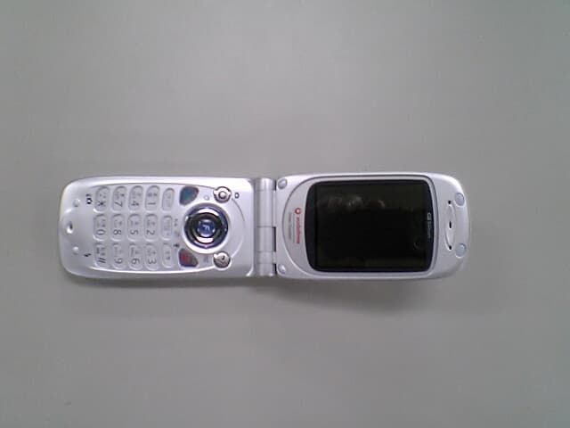
Click to zoom
Application Details
- Equipment Class
- PCE - PCS Licensed Transmitter held to ear
- Date of Grant
- Mar 31, 2004
- Application Purpose
- Original Equipment
- Date of Application
- Mar 31, 2004
- Equipment Note
- 1900 MHz GSM Cellular Phone
- Frequency Range
- 1850.20000000 - 1909.80000000
- Company
- Sharp Corporation
- Country
- Japan
Documents & Files
Document Text
Text extracted from the exhibit documents filed with the FCC. Open a document above to read the original.
Users Manual
V801 SH V801 SH Th is Manual includes an En glish Abridgement Glo bal Standard V801SH 16-1 Abridged English Manual For more information about handset operations and functions, please go to the Vodafone K.K. Website (www.vodafone.jp) for the full manual* or dial 157 from a Vodafone handset for Customer Service. Contents Accessories .................................... 16-2Safety Precautions ......................... 16-2General Notes ..............................16-10Minding Mobile Manners ..............16-14 ■ Basic Handset Etiquette....... 16-14 ■ Manner-Related Features..... 16-14 Handset Parts & Functions ...........16-15 ■ Handset (Front) .................... 16-15 ■ Handset (Side & Back) ......... 16-16 ■ Charging Battery .................. 16-18 ■ Display.................................. 16-20 ■ Symbols ................................ 16-23 ■ USIM Card ............................ 16-24 ■ USIM PINs ............................ 16-25 ■ Handset Codes .................... 16-25 Basic Handset Operations ............16-26 ■ Turning Handset On/Off ....... 16-26 ■ Display Language ................ 16-26 ■ Your Phone Number ............. 16-26 ■ Setting Clock ....................... 16-26 ■ Japan/International Mode..... 16-26 ■ Initiating a Call ...................... 16-26 ■ Redial ................................... 16-27 ■ Total Charges & Talk Time ... 16-27 ■ Incoming Call ....................... 16-27 ■ Placing a Caller on Hold....... 16-28 ■ Message Recorder & Voice Mail ... 16-28 ■ Forwarding a Call ................. 16-28 ■ Calling from Call History ....... 16-29 ■ Manner Mode ....................... 16-29 ■ Driving Mode ........................ 16-29 Entering Characters ......................16-30 ■ Character Types ................... 16-30 ■ Key Assignments.................. 16-31 ■ Symbols, Pictographs & Emoticons ... 16-32 Saving to Phone Book ..................16-33 ■ Phone Book Entry Items ....... 16-33 ■ New Phone Book Entries ...... 16-34 ■ Editing Phone Book .............. 16-35 ■ Saving from Call History ....... 16-35 Dialing from Phone Book ..............16-36 ■ Entry Number Search ........... 16-36 ■ Search by Reading............... 16-36 Mobile Camera .............................16-37 ■ Before Using Camera ........... 16-37 ■ Capturing Still Images .......... 16-37 Data Folder ...................................16-38 ■ Data Folder Contents............ 16-38 ■ Opening Data Folder ............ 16-39 ■ VGS Mail Attachments.......... 16-39 F Function Shortcuts ....................16-40Specifications ...............................16-44Customer Service .........................16-47 *Please note that the full manual may not be available in English at time of purchase. In this case, call Customer Service or check Vodafone Website again at a later date. 16-2 13151617 Abridged English Manual « Read safety precautions before using handset. « Observe precautions to avoid injury to self or others or damage to property. « Vodafone is not liable for any damages resulting from use of this product. ■ Symbols Make sure you thoroughly understand these symbols before reading on. Symbols and their meanings are described below: Accessories ■ Battery (SHBR01) * ( Type 1 lithium-ion battery ) ■ Rapid Charger (SHCR01) * ■ Desktop Holder (SHER01) * ■ Analog Conversion Cable ■ Optical Conversion Plug ■ Stereo Headphones ■ SD Memory Card ■ USB HOST Driver for V801SH (CD-ROM) *Additional quantities may be purchased separately. T Address accessory-related inquiries to Customer Service, General Information( AP. 16-47 ). Safety Precautions Before Using Handset D DD D A AA A N NN N G GG G E EE E R RR R Great risk of death or serious injury from improper use W WW W A AA A R RR R N NN N II I I N NN N G GG G Risk of death or serious injury from improper use C CC C A AA A U UU U T TT T II I I O OO O N NN N Risk of injury or damage to property from improper use 16-3 13151617 Abridged English Manual ■ Symbols Prohibited Actions Compulsory Actions Attention Required DANGER Handset, Battery & Charger ¤ Use only the specified battery, charger or holder Using non-specified equipment may cause malfunctions, electric shock or fire due to battery leakage, overheating or bursting. › Do not short-circuit charger terminals Keep metal objects away from charger terminals. Keep handset away from jewelry. Battery may leak, overheat, burst or ignite causing injury. Use a case to carry handset. Battery › Prevent injury from battery leakage, breakage or fire. Do not:« Heat or dispose of battery in fire. « Disassemble, modify or break battery. « Damage or solder battery. « Use a damaged or deformed battery. « Use non-specified charger. « Force battery into handset. « Charge or place battery near fire, heat sources or in extreme heat. « Use battery for other equipment. ¤ If battery fluid gets into eyes, do not rub them. Rinse with clean water and consult a doctor immediately. Eyes may be severely damaged. 16-4 13151617 Abridged English Manual WARNING Handset, Battery & Charger › Do not insert foreign objects into handset Do not put metal or flammable objects in handset, charger or holder. This may cause fire or electric shock. Keep handset out of the reach of children. fi Keep handset out of rain or extreme humidity Fire or electric shock may occur. › Keep handset away from liquid-filled containers Keep handset, charger and holder away from chemicals/liquids. Fire/electric shock may result. › Avoid sources of fire Prevent fire or explosion. Do not use handset in the presence of gas or fine particles (coal, dust, metal, etc.). › Do not use Mobile Light near people's faces Eyesight may be temporarily affected leading to accidents. › Keep SD Memory Card, Analog Conversion Cable & Optical Conversion Plug out of reach of small childrenIf swallowed accidentally, consult a doctor immediately. › Keep handset, charger or holder away from microwave ovensBattery or handset may leak, burst, overheat or ignite and cause accidents. f…
Text truncated - open the document above for the full version.
Cover Letter(s)
FDMA/TDMA(8slot) Class8 (TX: 1slot/RX:4slotTotal:5slot)
External Photos
V801SH Photo(External) V801SH Photo(External)V801SH Photo(External) V801SH Photo(External) V801SH Photo(External) V801SH Photo(External)V801SH Photo(External) V801SH Photo(External) V801SH Photo(Internal) V801SH Photo(Internal)V801SH Photo(Internal) V801SH Photo(Internal)
Internal Photos
V801SH Photo(Internal) V801SH Photo(Internal)V801SH Photo(Internal) V801SH Photo(Internal)
RF Exposure Info
IssueDate:March4,2004 Page 1 of 22 EMC SAR - TEST REPORT JQA APPLICATION No.: KL80030710 Name of Product: GSM-WCDMA Dual Cellular Phone Model/Type No.: V801SH FCC ID: APYHRO00032 Applicant : Sharp Corporation, Communication Systems Group Address : 2-13-1, Iida, Hachihonmatsu, Higashi-Hiroshima City, Hiroshima, 739-0192, Japan Manufacturer : Sharp Corporation, Communication Systems Group Address : 2-13-1, Iida, Hachihonmatsu, Higashi-Hiroshima City, Hiroshima, 739-0192, Japan Receive date of EUT: February 9, 2004 Final Judgement :Passed TEST RESULTS IN THIS REPORT are obtained in use of equipment that is traceable to National Institute of Advanced Industrial Science and Technology (AIST) under METI Japan, Communications Research Lab. (CRL) under MPHPT Japan, and Laboratory for EMF and Microwave Electronics at the Swiss Federal Authorized by: Institute of Technology (ETH) in Zürich, Switzerland. THE TEST RESULTS only responds to the test sample.Thistestreportshallnotbereproduced Takashi Yamanaka, Director except in full. JQA KITA-KANSAI Testing Center Page 2 of 22 DIRECTORY Page A) Documentation Directory2 Test Regulation / General Information3 - 5 SAR Measurement Set-up6 Test Configuration Positions7 - 9 Measurement Process10 Measurement Uncertainties11 Test Conditions12 EUT Tune-up Procedure13 EUT Modification / Responsible Party / Deviation from Standard14 Test results15 Summary16 EUT Photographs17 B) Test data Test System Validation18 Tissue Simulant Verification19 SAR Measurement Data20 - 21 Appendix22 JQA Application No. : KL80030710Regulation : CFR 47 FCC Rules Part 2 Model No.: V801SHIssue Date : March 4, 2004 FCC ID: APYHRO00032 JQA Application No. : KL80030710Regulation : CFR 47 FCC Rules Part 2 Model No.: V801SHIssue Date : March 4, 2004 FCC ID: APYHRO00032 Page 3 of 22 TEST REGULATION FCC Rules and Regulations Parts 2 Subpart J (October 1, 2002) {{- Mobile Devices (§2.1091)- Occupational/Controlled Exposure zz- Portable Devices (§2.1093)- General Population/Uncontrolled Exposure Test procedure: The SAR measurement procedures were specified in FCC/OET Bulletin 65 Supplement C (July, 2001) and IEEE Std. 1528-200X (Draft 6.5, January 2002). The exposure limits were specified in ANSI/IEEE C95.1-1999. GENERAL INFORMATION Description of the Equipment Under Test (EUT): 1) Name: GSM-WCDMA Dual Cellular Phone 2) Model/Type No.: V801SH 3) Product Type: Pre-production (S/N: 350228/00/004002/5) 4) EUT Authorization: - Verification- Certification- D.o.C.{z { 5) Transmitting Frequency: 1850.20 MHz - 1909.80 MHz 6) Receiving Frequency: 1930.20 MHz - 1989.80 MHz 7) Max. RF Output Power: 29.34 dBm 8) Power Rating: 4.0VDC Note : This device contains GSM 900 MHz, DCS 1800 MHz and WCDMA functions not operational in U.S. territories. This report is only appliance for PCS 1900 MHz band. Definitions for symbols used in this test report: z- Black box indicates that the listed condition, standard or equipment is applicable for this Report. {- Blank box indicates that the listed condition, standard or equipment is not applicable for this Report. JQA Application No. : KL80030710Regulation : CFR 47 FCC Rules Part 2 Model No.: V801SHIssue Date : March 4, 2004 FCC ID: APYHRO00032 Page 4 of 22 Description of the Antenna: Type: Fixed mono-pole antenna Dimensions: Maximum width 5.1 mm Maximum length 34.0 mm Location: Left side Battery Option: Lithium-ion Battery Pack SHBR01 (740mAh) Probe Specification: Construction: Symmetrical design with triangular core Built-in optical fiber for surface detection system Built-in shielding against static changes Calibration: In air form 10 MHz to 2.5 GHz In head tissue simulating liquid (HSL) and muscle tissue simulating liquid 900 MHz (accuracy ± 11.3%; k=2) 1800 MHz (accuracy ± 11.7%; k=2) 2450 MHz (accuracy ± 9.7%; k=2) Frequency: 10MHzto3GHz(dosimetry); Linearity: ±0.2 dB (30 MHz to 3 GHz) Directivity: ± 0.2 dB in HSL (rotation around probe axis) ± 0.4 dB in HSL (rotation normal probe axis) Dynamic Range: 5 μW/g to >100 mW/g; Linearity: ± 0.2 dB Surface Detection : ± 0.2 mm repeatability in air and clear liquids over diffuse reflecting surfaces Dimensions: Overall length 330 mm Tiplength16mm Body diameter 12 mm Tip diameter 6.8 mm Distance from probe tip to dipole centers 2.7 mm JQA Application No. : KL80030710Regulation : CFR 47 FCC Rules Part 2 Model No.: V801SHIssue Date : March 4, 2004 FCC ID: APYHRO00032 Page 5 of 22 Twin SAM Phantom: The shell corresponds to the specifications of the Specific Anthropomorphic Mannequin (SAM) phantom defined in IEEE 1528-200X, CENELEC 50361 and IEC 62209. It enables the dosimetric evaluation of left and right head phone usage as well as body mounted usage at the flat phantom region. A cover prevents evaporation of the liquid. Reference markings on the phantom allow the complete setup of all predefined phantom positions and measurement grids by manually teaching three points with the robot. Shell Thickness: 2 ± 0.2 mm Filling Volume: Volume Approx. 25 liters Dimensions: 810 × 1000 × 500 mm (H × L × W) Mounting Device for Transmitters: The Mounting Device enables the rotation of the mounted transmitter in spherical coordinates, whereby the rotation point is the ear opening. The devices can be easily and accurately positioned according to IEC, IEEE, CENELEC, FCC or other specifications. The device holder can be locked at different phantom locations (left head, right head, flat phantom). Typical Composition of Ingredients for Liquid Tissue: IngredientsFrequency (MHz) (% by weight)83519002450 HeadBodyHeadBodyHeadBody Water41.4552.4054.9040.4062.7073.20 Salt (NaCl)1.451.400.180.500.500.04 Sugar56.0045.000.0058.000.000.00 HEC1.001.000.001.000.000.00 Bactericide 0.100.100.000.100.000.00 TritonX-1000.000.000.000.0036.800.00 DGBE0.000.0044.920.000.0026.70 Salt : 99 % Pure Sodium ChlorideSugar : 98 % Pure Sucrose ++ Water : De-ionized, 16 M resistivityHEC : Hydroxyethyl CelluloseΩ + DGBE : 99 % Di (ethylene glycol) butyl ether, [2-(2-butoxyeth…
Text truncated - open the document above for the full version.
RF Exposure Info
APPENDIX Exhibit 1 System Validation Plots Date/Time: 02/27/04 12:03:12 Test Laboratory: JAPAN QUALITY ASSURANCE ORGANIZATION File Name: Validation_HSL1800_040227.da4 System Validation DUT: Dipole 1800 MHz; Type: D1800V2; Serial: 2d038 Program: Validation Communication System: CW; Frequency: 1800 MHz;Duty Cycle: 1:1 Medium: HSL1800 (σ = 1.454 mho/m, ε r = 38.39, ρ = 1000 kg/m 3 ) Phantom section: Flat Section Measurement Standard: DASY4 (High Precision Assessment) DASY4 Configuration: zProbe: ET3DV6 - SN1678; ConvF(5.15, 5.15, 5.15); Calibrated: 2004/02/15 zSensor-Surface: 4mm (Mechanical And Optical Surface Detection) zElectronics: DAE3 Sn508; Calibrated: 2004/02/06 zPhantom: SAM 1194; Type: QD 000 P40 CA; Serial: 1194 zMeasurement SW: DASY4, V4.1 Build 47; Postprocessing SW: SEMCAD, V1.6 Build 115 Antenna Input Power 250 mW/Area Scan (5x5x1): Measurement grid: dx=20mm, dy=20mm Reference Value = 91.5 V/m Power Drift = -0.007 dB Maximum value of SAR = 10.9 mW/g Antenna Input Power 250 mW/Zoom Scan (5x5x7)/Cube 0: Measurement grid: dx=8mm, dy=8mm, dz=5mm Peak SAR (extrapolated) = 18 W/kg SAR(1 g) = 10.2 mW/g; SAR(10 g) = 5.26 mW/g Reference Value = 91.5 V/m Power Drift = -0.007 dB Maximum value of SAR = 11.3 mW/g 0 dB = 11.3mW/g Date/Time: 03/01/04 10:59:40 Test Laboratory: JAPAN QUALITY ASSURANCE ORGANIZATION File Name: Validation_040301.da4 System Validation DUT: Dipole 1800 MHz; Type: D1800V2; Serial: 2d038 Program: Validation Communication System: CW; Frequency: 1800 MHz;Duty Cycle: 1:1 Medium: M1800 (σ = 1.555 mho/m, ε r = 53.92, ρ = 1000 kg/m 3 ) Phantom section: Flat Section Measurement Standard: DASY4 (High Precision Assessment) DASY4 Configuration: zProbe: ET3DV6 - SN1678; ConvF(4.65, 4.65, 4.65); Calibrated: 2004/02/15 zSensor-Surface: 4mm (Mechanical And Optical Surface Detection) zElectronics: DAE3 Sn508; Calibrated: 2004/02/06 zPhantom: SAM 1194; Type: QD 000 P40 CA; Serial: 1194 zMeasurement SW: DASY4, V4.1 Build 47; Postprocessing SW: SEMCAD, V1.6 Build 115 Antenna Input Power 250 mW/Area Scan (5x5x1): Measurement grid: dx=20mm, dy=20mm Reference Value = 89.2 V/m Power Drift = -0.09 dB Maximum value of SAR = 10.8 mW/g Antenna Input Power 250 mW/Zoom Scan (5x5x7)/Cube 0: Measurement grid: dx=8mm, dy=8mm, dz=5mm Peak SAR (extrapolated) = 16.1 W/kg SAR(1 g) = 9.66 mW/g; SAR(10 g) = 5.11 mW/g Reference Value = 89.2 V/m Power Drift = -0.09 dB Maximum value of SAR = 10.8 mW/g 0 dB = 10.8mW/g
RF Exposure Info
APPENDIX Exhibit 2 SAR Test Plots Date/Time: 02/27/04 13:37:36 Test Laboratory: JAPAN QUALITY ASSURANCE ORGANIZATION File Name: Left_low_touch.da4 Cheek/Touch 0512ch (1850.20MHz) DUT: GSM-WCDMA Dual Cellular Phone; Type: V801SH; Serial: 350228/00/004002/5 Program: Left Head Communication System: GSM 1900; Frequency: 1850.2 MHz;Duty Cycle: 1:8.5 Medium: HSL1900 (σ = 1.441 mho/m, ε r = 38.16, ρ = 1000 kg/m 3 ) Phantom section: Left Section Measurement Standard: DASY4 (High Precision Assessment) DASY4 Configuration: zProbe: ET3DV6 - SN1678; ConvF(5.15, 5.15, 5.15); Calibrated: 2004/02/15 zSensor-Surface: 4mm (Mechanical And Optical Surface Detection) zElectronics: DAE3 Sn508; Calibrated: 2004/02/06 zPhantom: SAM 1194; Type: QD 000 P40 CA; Serial: 1194 zMeasurement SW: DASY4, V4.1 Build 47; Postprocessing SW: SEMCAD, V1.6 Build 115 Cheek/Touch Position/Area Scan (16x10x1): Measurement grid: dx=10mm, dy=10mm Reference Value = 4.74 V/m Power Drift = -0.1 dB Maximum value of SAR = 0.422 mW/g Cheek/Touch Position/Zoom Scan (5x5x7)/Cube 0: Measurement grid: dx=8mm, dy=8mm, dz=5mm Peak SAR (extrapolated) = 0.65 W/kg SAR(1 g) = 0.394 mW/g; SAR(10 g) = 0.225 mW/g Reference Value = 4.74 V/m Power Drift = -0.1 dB Maximum value of SAR = 0.433 mW/g 0 dB = 0.433mW/g Date/Time: 02/27/04 14:11:46 Test Laboratory: JAPAN QUALITY ASSURANCE ORGANIZATION File Name: Left_middle_touch.da4 Cheek/Touch 0661ch (1880.00MHz) DUT: GSM-WCDMA Dual Cellular Phone; Type: V801SH; Serial: 350228/00/004002/5 Program: Left Head Communication System: GSM 1900; Frequency: 1880 MHz;Duty Cycle: 1:8.5 Medium: HSL1900 (σ = 1.441 mho/m, ε r = 38.16, ρ = 1000 kg/m 3 ) Phantom section: Left Section Measurement Standard: DASY4 (High Precision Assessment) DASY4 Configuration: zProbe: ET3DV6 - SN1678; ConvF(5.15, 5.15, 5.15); Calibrated: 2004/02/15 zSensor-Surface: 4mm (Mechanical And Optical Surface Detection) zElectronics: DAE3 Sn508; Calibrated: 2004/02/06 zPhantom: SAM 1194; Type: QD 000 P40 CA; Serial: 1194 zMeasurement SW: DASY4, V4.1 Build 47; Postprocessing SW: SEMCAD, V1.6 Build 115 Cheek/Touch Position/Area Scan (16x10x1): Measurement grid: dx=10mm, dy=10mm Reference Value = 5.32 V/m Power Drift = -0.04 dB Maximum value of SAR = 0.525 mW/g Cheek/Touch Position/Zoom Scan (5x5x7)/Cube 0: Measurement grid: dx=8mm, dy=8mm, dz=5mm Peak SAR (extrapolated) = 0.814 W/kg SAR(1 g) = 0.489 mW/g; SAR(10 g) = 0.273 mW/g Reference Value = 5.32 V/m Power Drift = -0.04 dB Maximum value of SAR = 0.538 mW/g 0 dB = 0.538mW/g Date/Time: 02/27/04 14:38:54 Test Laboratory: JAPAN QUALITY ASSURANCE ORGANIZATION File Name: Left_high_touch.da4 Cheek/Touch 0810ch (1909.80MHz) DUT: GSM-WCDMA Dual Cellular Phone; Type: V801SH; Serial: 350228/00/004002/5 Program: Left Head Communication System: GSM 1900; Frequency: 1909.8 MHz;Duty Cycle: 1:8.5 Medium: HSL1900 (σ = 1.441 mho/m, ε r = 38.16, ρ = 1000 kg/m 3 ) Phantom section: Left Section Measurement Standard: DASY4 (High Precision Assessment) DASY4 Configuration: zProbe: ET3DV6 - SN1678; ConvF(5.15, 5.15, 5.15); Calibrated: 2004/02/15 zSensor-Surface: 4mm (Mechanical And Optical Surface Detection) zElectronics: DAE3 Sn508; Calibrated: 2004/02/06 zPhantom: SAM 1194; Type: QD 000 P40 CA; Serial: 1194 zMeasurement SW: DASY4, V4.1 Build 47; Postprocessing SW: SEMCAD, V1.6 Build 115 Cheek/Touch Position/Area Scan (16x10x1): Measurement grid: dx=10mm, dy=10mm Reference Value = 5.12 V/m Power Drift = -0.03 dB Maximum value of SAR = 0.523 mW/g Cheek/Touch Position/Zoom Scan (5x5x7)/Cube 0: Measurement grid: dx=8mm, dy=8mm, dz=5mm Peak SAR (extrapolated) = 0.775 W/kg SAR(1 g) = 0.468 mW/g; SAR(10 g) = 0.259 mW/g Reference Value = 5.12 V/m Power Drift = -0.03 dB Maximum value of SAR = 0.519 mW/g 0 dB = 0.519mW/g Date/Time: 02/27/04 16:10:38 Test Laboratory: JAPAN QUALITY ASSURANCE ORGANIZATION File Name: Left_low_tilt.da4 Ear/Tilt 0512ch (1850.20MHz) DUT: GSM-WCDMA Dual Cellular Phone; Type: V801SH; Serial: 350228/00/004002/5 Program: Left Head Communication System: GSM 1900; Frequency: 1850.2 MHz;Duty Cycle: 1:8.5 Medium: HSL1900 (σ = 1.441 mho/m, ε r = 38.16, ρ = 1000 kg/m 3 ) Phantom section: Left Section Measurement Standard: DASY4 (High Precision Assessment) DASY4 Configuration: zProbe: ET3DV6 - SN1678; ConvF(5.15, 5.15, 5.15); Calibrated: 2004/02/15 zSensor-Surface: 4mm (Mechanical And Optical Surface Detection) zElectronics: DAE3 Sn508; Calibrated: 2004/02/06 zPhantom: SAM 1194; Type: QD 000 P40 CA; Serial: 1194 zMeasurement SW: DASY4, V4.1 Build 47; Postprocessing SW: SEMCAD, V1.6 Build 115 Ear/Tilt Position/Area Scan (16x10x1): Measurement grid: dx=10mm, dy=10mm Reference Value = 9.56 V/m Power Drift = -0.04 dB Maximum value of SAR = 0.135 mW/g Ear/Tilt Position/Zoom Scan (5x5x7)/Cube 0: Measurement grid: dx=8mm, dy=8mm, dz=5mm Peak SAR (extrapolated) = 0.191 W/kg SAR(1 g) = 0.13 mW/g; SAR(10 g) = 0.0837 mW/g Reference Value = 9.56 V/m Power Drift = -0.04 dB Maximum value of SAR = 0.136 mW/g 0 dB = 0.136mW/g Date/Time: 02/27/04 15:16:26 Test Laboratory: JAPAN QUALITY ASSURANCE ORGANIZATION File Name: Left_middle_tilt.da4 Ear/Tilt 0661ch (1880.00MHz) DUT: GSM-WCDMA Dual Cellular Phone; Type: V801SH; Serial: 350228/00/004002/5 Program: Left Head Communication System: GSM 1900; Frequency: 1880 MHz;Duty Cycle: 1:8.5 Medium: HSL1900 (σ = 1.441 mho/m, ε r = 38.16, ρ = 1000 kg/m 3 ) Phantom section: Left Section Measurement Standard: DASY4 (High Precision Assessment) DASY4 Configuration: zProbe: ET3DV6 - SN1678; ConvF(5.15, 5.15, 5.15); Calibrated: 2004/02/15 zSensor-Surface: 4mm (Mechanical And Optical Surface Detection) zElectronics: DAE3 Sn508; Calibrated: 2004/02/06 zPhantom: SAM 1194; Type: QD 000 P40 CA; Serial: 1194 zMeasurement SW: DASY4, V4.1 Build 47; Postprocessing SW: SEMCAD, V1.6 Build 115 Ear/Tilt Position/Area Scan (16x10x1): Measurement grid: dx=10mm, dy=10mm Reference Value = 10.1 V/m Power Drift = -0.005 dB Maximum value of SAR = 0.157 mW/g Ear/Tilt Position/Zoom Scan (5x5x7)/Cube 0: Measurement gri…
Text truncated - open the document above for the full version.
RF Exposure Info
APPENDIX Exhibit 3 Dosimetric E-Field Probe - ET3DV6, S/N: 1678 Calibration Data
RF Exposure Info
APPENDIX Exhibit 4 System Validation Dipole - D1800V2, S/N: 2d038 Calibration Data
RF Exposure Info
APPENDIX Exhibit 5 Transmitted Duty Cycle Plots Duty Cycle Plots Modulation Type: GSM 1900 Duty Cycle: 100 × (0.540/4.580) = 11.79% Duty Cycle Plots Modulation Type: GPRS 1900 Duty Cycle: 100 × (0.540/4.580) = 11.79%
Test Report
IssueDate:March4,2004 Page 1 of 36 TEST REPORTEMCEMISSION - JQA APPLICATION No.: KL80030711 Name of Product: GSM-WCDMA Dual Cellular Phone Model/Type No.: V801SH FCC ID: APYHRO00032 Applicant: Sharp Corporation, Communication Systems Group Address: 2-13-1, Iida Hachihonmatsu, Higashihiroshima-city, : Hiroshima 739-0192, JAPAN Manufacturer: Sharp Corporation, Communication Systems Group Address: 2-13-1, Iida Hachihonmatsu, Higashihiroshima-city, : Hiroshima 739-0192, JAPAN February 9, 2004Receive date of EUT: passedFinal Judgement: are obtained in use of equipment that is traceable to National TEST RESULTS IN THIS REPORT Institute of Advanced Industrial Science and Technology (AIST) under METI Japan and Communications Research Lab. (CRL) under MPHPT Japan. only responds to the test sample. This test report shall not be reproduced THE TEST RESULTS except in full. Authorized by: Takashi Yamanaka, Director JQA KITA-KANSAI Testing Center Page 2 of 36 DIRECTORY Page A) Documentation Directory2 Test Regulation / General Information3 - 4 Test Conditions5-18 Configuration of EUT / Operation mode of the EUT19 - 20 EUT Modification / Responsible Party / Deviation from Standard21 Test results / Measurement Uncertainty22 - 24 Summary25 26Test System-Arrangement (Drawings) 27Test-setup (Photographs) at worst case B) Test data - PCS1900 - Transmitter Power(TP)28 Antenna Conducted Spurious Emission29 - 30 Transmitter Power(EIRP)31 Unwanted Radiation32 - 33 Occupied Bandwidth34 Band-Edge Emission35 Frequency Stability36 JQA Application No.: KL80030711Regulation: CFR 47 FCC Rules Part 24 Model No.: V801SHIssue Date: March 4, 2004 FCC ID: APYHRO00032 JQA Application No.: KL80030711Regulation: CFR 47 FCC Rules Part 24 Model No.: V801SHIssue Date: March 4, 2004 FCC ID: APYHRO00032 Page 3 of 36 TEST REGULATION FCC Rules and Regulations Part 24 (October 1, 2002) 1900 MHz systems (Part 24) - Narrowband PCS{ - Broadband PCSz Test procedure: The tests were performed according to FCC Rules and Regulations Part 2 (October 1, 2002), and ANSI C63.4 (2001). GENERAL INFORMATION Test facility: 1) Test Facility located at Kita-Kansai: 1st Open Site (3 m Site) Test Facility located at Kameoka: 1st Open Site (3, 10 and 30 m, on common plane) : 2nd Open Site (3 and 10 m, on common plane) FCC filing No. : 31040/SIT 1300F2 2) KITA-KANSAI TESTING CENTER is recognizedunder the National Voluntary Laboratory Accreditation Program for satisfactory compliance established in Title 15, Part 285 Code of Federal Regulations. NVLAP Lab Code: 200191-0 Definitions for symbols used in this test report: - Black box indicates that the listed condition, standard or equipment is applicablez for this Report. - Blank box indicates that the listed condition, standard or equipment is not applicable{ for this Report. JQA Application No.: KL80030711Regulation: CFR 47 FCC Rules Part 24 Model No.: V801SHIssue Date: March 4, 2004 FCC ID: APYHRO00032 Page 4 of 36 Description of the Equipment Under Test (EUT): 1) Name: GSM-WCDMA Dual Cellular Phone 2) Model/Type No.: V801SH 3) Product Type: Pre-Production(Serial No.: 350228/00/004002/5) 4) Category: Broadband PCS 5) EUT Authorization:- Verification- Certification- D.o.C.{z { 6) Transmitting Frequency: 1850.2 MHz (512 ch) - 1909.8 MHz (810 ch)(PCS1900) 7) Receiving Frequency: 1930.2 MHz (512 ch) - 1989.8 MHz (810 ch) (PCS1900) 8) Integrated Antenna: Shortened Mono-pole Antenna 9) Emission Designations: 253KGXW(PCS1900) 10) Maximum RF Output Power: 1.300W(EIRP)(PCS1900) 11) Power Rating: 4.0VDC 12) Channel Numbers and Frequencies : PCS1900 Thecarrierspacingis200kHz. The carrier frequency is designated by the absolute frequency channel number (ARFCN). The carrier frequency is expressed in the equation shown as follows: TX frequency (in MHz) = 1850.2 + 0.2 × (n -512) RX frequency (in MHz) = 1930.2 + 0.2 × (n -512) Where n : Channel Number (512 n 810)≤≤ 13) Modulation Type : GMSK 14) Type of Communication System : GSM JQA Application No.: KL80030711Regulation: CFR 47 FCC Rules Part 24 Model No.: V801SHIssue Date: March 4, 2004 FCC ID: APYHRO00032 Page 5 of 36 TEST CONDITIONS Transmitter Power (TP) Measurement (§2.1046(a)) Test Procedure : The Transmitter Power was measured with a power meter, one 10 dB attenuator and a short, low loss cable. EUT10 dBPowerAntenna AttenuatorMeterTerminal Fig.1 Transmitter Power Measurement Test location : KITA-KANSAI Testing Center 7-7, Ishimaru, 1-Chome, Mino-Shi, Osaka, 562-0027, Japan -Shieldedroom{ KAMEOKA EMC Branch 9-1, Ozaki, Inukanno, Nishibetsuin-Cho, Kameoka-Shi, Kyoto, 621-0126, Japan -Shieldedroomz Used test instruments and sites : Model No.Device IDLast Cal. DateCal. Interval - E4417AB - 51August, 20031 Yearz - E9321AB - 52May, 20031 Yearz -6-20D-27{ - 4T-10D - 73{ - 4T-10D - 74{ -2-10D-79{ -2-10D-80{ - 54-10D - 82November, 20031 Yearz - 54-10D - 83{ Environmental conditions : Temperature:19 °CHumidity:39% JQA Application No.: KL80030711Regulation: CFR 47 FCC Rules Part 24 Model No.: V801SHIssue Date: March 4, 2004 FCC ID: APYHRO00032 Page 6 of 36 Antenna Conducted Spurious EmissionMeasurement (§2.1051,§24.238 ) Test Procedure : The Antenna Conducted Emission was measured with a spectrum analyzer. The test system is shown as follows: PCS1900 1) Frequency Range : 9kHz - 2.2GHz EUT10 dBSpectrumAntenna Att.(D-73)AnalyzerTerminal 2) Frequency Range : 2.2GHz -5.8GHz EUTHigh Pass10 dBPre-Amp.10dBSpectrumAntenna Filter(D-42)Att.(D-73)(A-21)Att.(D-74)AnalyzerTerminal 3) Frequency Range : 5.8GHz - 20GHz EUTHigh Pass10 dBPre-Amp.10dBSpectrumAntenna Filter(D-42)Att.(D-73)(A-33)Att.(D-74)AnalyzerTerminal Fig.2 Antenna Conducted Spurious Emission Measurement JQA Application No.: KL80030711Regulation: CFR 47 FCC Rules Part 24 Model No.: V801SHIssue Date: March 4, 2004 FCC ID: APYHRO00032 Page 7 of 36 Test location : KITA-KANSAI Testing Center 7-7, Ishimaru, 1-Chome, Mino-Shi, Osaka, 562-0027, Japan -Shieldedroomz KAMEOKA EMC Branch 9-1, Ozaki, Inukanno, Nishibetsuin-Cho, Kameoka…
Text truncated - open the document above for the full version.
Test Report
Page 1 of 7 Attachment A Occupied Bandwidth Measurement PCS1900 Test Date: February 10, 2004 Temp.: 20 ; Humi.: 40 %°C CHTransmitting26dB99%Data No.Frequency(MHz)BandwidthBandwidthPage 5121850.200321 kHz251 kHzPage 2 6611880.000324 kHz253 kHzPage 3 8101909.800319 kHz250 kHzPage 4 .Note) The point shown on "" is the Maximum Point Tester : Shigeru Kinoshita JQA Application No.: KL80030711Regulation : CFR 47 FCC Rules Part 24 Model No.: V801SHIssue Date : March 4, 2004 FCC ID: APYHRO00032 Page 2 of 7 Occupied Bandwidth Measurement Transmitting Frequency : 1850.200MHz (512 ch) JQA Application No.: KL80030711Regulation : CFR 47 FCC Rules Part 24 Model No.: V801SHIssue Date : March 4, 2004 FCC ID: APYHRO00032 JQA Application No.: KL80030711Regulation : CFR 47 FCC Rules Part 24 Model No.: V801SHIssue Date : March 4, 2004 FCC ID: APYHRO00032 Page 3 of 7 Occupied Bandwidth Measurement Transmitting Frequency : 1880.000MHz (661 ch) JQA Application No.: KL80030711Regulation : CFR 47 FCC Rules Part 24 Model No.: V801SHIssue Date : March 4, 2004 FCC ID: APYHRO00032 Page 4 of 7 Occupied Bandwidth Measurement Transmitting Frequency : 1909.800MHz (810 ch) JQA Application No.: KL80030711Regulation : CFR 47 FCC Rules Part 24 Model No.: V801SHIssue Date : March 4, 2004 FCC ID: APYHRO00032 Page 5 of 7 Band-Edge Emission Measurement PCS1900 Test Date: February 10, 2004 Temp.: 20 ; Humi.: 40 %°C 1) Low Band-Edge Measurement CHTransmittingBand-Edge Band-EdgeData Frequency(MHz)Frequency(MHz) Level[dBc]Page 5121850.2001850.000-41.4Page 6 2) High Band-Edge Measurement CHTransmittingBand-Edge Band-EdgeData Frequency(MHz)Frequency(MHz) Level[dBc]Page 8101909.8001910.000-38.4Page 7 Note) 1. *: The Data Page is one in Attachment A. 2..The point shown on "" is the Minimum Point Tester : Shigeru Kinoshita JQA Application No.: KL80030711Regulation : CFR 47 FCC Rules Part 24 Model No.: V801SHIssue Date : March 4, 2004 FCC ID: APYHRO00032 Page 6 of 7 Band-Edge Emissiom Measurement Transmitting Frequency : 1850.200MHz (512 ch) Band-Edge Frequency: 1850.000 MHz JQA Application No.: KL80030711Regulation : CFR 47 FCC Rules Part 24 Model No.: V801SHIssue Date : March 4, 2004 FCC ID: APYHRO00032 Page 7 of 7 Band-Edge Emissiom Measurement Transmitting Frequency : 1909.800MHz (810 ch) Band-Edge Frequency: 1910.000 MHz
Test Report
Page 1 of 13 Attachment B Antenna Conducted Spurious EmissionMeasurement (§2.1051,§24.238 ) Test Procedure : The Antenna Conducted Emission was measured with a spectrum analyzer. The test system is shown as follows: PCS1900 1) Frequency Range : 9kHz - 2.2GHz EUT10 dBSpectrumAntenna Att.(D-73)AnalyzerTerminal 2) Frequency Range : 2.2GHz -5.8GHz EUTHigh Pass10 dBPre-Amp.10dBSpectrumAntenna Filter(D-42) Att.(D-73) (A-21)Att.(D-74) AnalyzerTerminal…
Text truncated - open the document above for the full version.
Contact Information
Applicant
Taihei Ohtsuka(Deputy Division Manager, ESG & Q promotion unit)
Test Firm
Japan Qlty. Assur. Org. Kitakansai Testing CenterHiroyuki Nakamura
Technical Specifications
| # | Rule Parts | Frequency Range | Power Output | Emission | Tolerance |
|---|---|---|---|---|---|
| 1 | 24E | 1.85 GHz - 1.91 GHz | 1.3 W | 253KGXW | 2.5000000000 ppm |
Other Applications from Sharp Corporation
APYHRO00343
Aug 17, 2026Smartphone
Equipment Class
DTS - Digital Transmission SystemAPYHRO00342
Jul 29, 2026Smart phone
Equipment Class
DXX - Part 15 Low Power Communication Device TransmitterAPYHRO00341
May 28, 2026Smart phone
Equipment Class
DTS - Digital Transmission SystemAPYHRO00340
Dec 01, 2025BT remote control
Equipment Class
DTS - Digital Transmission SystemAPYHRO00339
Sep 17, 2025Smart phone
Equipment Class
NII - Unlicensed National Information Infrastructure TX