APYHRO00061Cellular Transceiver
Sharp Corporation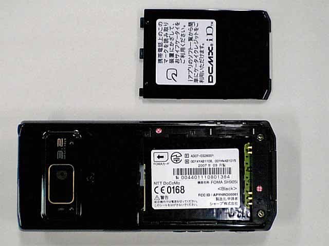
Click to zoom
Application Details
- Equipment Class
- PCE - PCS Licensed Transmitter held to ear
- Date of Grant
- Oct 11, 2007
- Application Purpose
- Original Equipment
- Date of Application
- Oct 11, 2007
- Equipment Note
- Cellular Transceiver
- Frequency Range
- 1850.20000000 - 1909.80000000
- Company
- Sharp Corporation
- Country
- Japan
Documents & Files
Document Text
Text extracted from the exhibit documents filed with the FCC. Open a document above to read the original.
Users Manual
50 e02_dv50_7e.fm Before Using the Handset dv50_e.book 50 ページ 2007年9月7日 金曜日 午前8時47分 24 e02_dv50_7e.fm Before Using the Handset ※Key illustrations are examples and may look different from actual keys. 1Earpiece Emits the other party’s voice. When in stand-by, listen to Record message/Voice memo using the earpiece. 2Display (nP. 28) 3i-mode/Guidance key i (,) Press to make or receive a Videophone call ( nP. 53, P. 67). Press to use i-mode (nP. 184). Press to execute the function displayed at the lower left of the display in guidance ( nP. 27). In stand-by, press twice to display the i- appli screen. Press for 1+ seconds to display the i- appli software list screen ( nP. 253). 4Multi-guide key (four-way key w and OK key t) (nP. 27) Press to display/select Menu, Redial, Received calls, Shortcut menu, Active marker ( nP. 405) as well as use these functions. In stand-by, press t for 1+ seconds to set/cancel Multi easy lock ( nP. 150). To disable, terminal security code is required. In stand-by, press r for 1+ seconds to set/cancel IC card lock ( nP. 278). To disable, terminal security code is required. In stand-by, press u for 1+ seconds to adjust earpiece volume ( nP. 128). 5Mail/Guidance key m Press to use mail functions (nP. 210). Component Names and Functions v u t i f e h d g c 2 1 6 9 4 5 o m l a b 3 8 k j n p q r l s z y x w 7 The brightness sensor area When Brightness of Light/Power Saver (nP. 134, P. 136) is set to [Automatic], the sensor detects the light of the surrounding area and automatically adjusts the display brightness and keypad backlight. Do not cover the sensor area ( a) with a sticker. May interfere with the sensor. dv50_e.book 24 ページ 2007年9月7日 金曜日 午前8時47分 25 e02_dv50_7e.fm Before Using the Handset Continued on next page ?? In stand-by, press for 1+ seconds to display a new mail message screen ( nP. 211). Press twice to check new messages ( nP. 211, P. 223). Press to execute the function displayed at the lower left of the display in guidance ( nP. 27). Press to switch between upper and lower case when entering text ( nP. 429). Press for 1+ seconds in text input screen to use emoticons ( nP. 433). Press for 1+ seconds while Mail ticker is being displayed to to view Inbox ( nP. 222). 6Start/Hands-free key s Press to make or receive a voice call. Press for 1+ seconds during a voice call to turn Hands-free on and off ( nP. 55). Press during a Videophone call to turn Hands-free ON/OFF ( nP. 84). Press during a PushTalk transmission to turn Hands-free ON/OFF ( nP. 91). 7microSD Memory Card slot (nP. 343) Insert a microSD Memory Card. 8Charger terminal (nP. 44) Terminal for recharging with the desktop holder. 9b/Line break/Public mode (Drive mode) key * Press to enter an [b] (asterisk), [ ゙] (dakuten), [ ゚] (handakuten) or a line break ( nP. 429). In stand-by, press for 1+ seconds to set/ cancel Public mode (Drive mode) ( nP. 72). In text input screen, press for 1+ seconds to paste text ( nP. 434). aBrightness sensor (nP. 134, P. 136) The sensor detects the light of the surrounding area and automatically adjusts the display brightness and key backlight ON/OFF. bUp/Down key (front) -, _ Use for camera function or music player. Press while charging in the viewer position to show the desktop clock ( nP. 132). Press - for 1+ seconds while running an application in the viewer position to use the phonebook, mail or other functions ( nP. 298). cTOUCH CRUISER pad (nP. 28) dCamera/Guidance key C Press to activate Camera (nP. 163). Press to execute the function displayed at the lower right of the display in guidance ( nP. 27). In stand-by, press for 1+ seconds to display Data box ( nP. 356). ePhonebook/Guidance key a Press to use the phonebook (nP. 102). In stand-by, press for 1+ seconds to display the phonebook entry screen ( nP. 104, P. 108). Press to execute the function displayed at the lower right of the display in guidance ( nP. 27). Press to change the type of text to be entered ( nP. 430). In text input screen, press for 1+ seconds to display insert phrase screen ( nP. 432). fi-Channel/Clear/i-appli stand-by key c ( J) Press to show the channel list (nP. 206). Use to delete phone numbers and text ( nP. 430). Press to return to the previous screen. Press when i-appli stand-by is set and i- appli starts (nP. 263). gPower/End/On hold key H Press for 2+ seconds to turn the power on/ off ( nP. 45). Press to end a call or i-mode, or to put calls on hold ( nP. 71). Press to play/pause when animated GIF or Flash movies are set as the stand-by display. Press while setting i-motion to play/stop ( nP. 131). hDial/Text entry keys 1 to 9, 0 Press to enter a phone number (nP. 53). Press to enter text (nP. 428). i#/Manner mode key # Press to enter a [#], [ー] (prolonged sound), [ 、] (touten), [。] (kuten), [!] (exclamation mark), [?] (question mark), or [ ・] (chuten). When in the normal position, press for 1+ seconds in stand-by to set/disable Manner mode ( nP. 129). In text input screen, press for 1+ seconds to cut text ( nP. 434). jMulti/GPS/Supportbook key $ To activate Multi Assistant: Press while running an application to use the phonebook, mail or other useful functions ( nP. 404). GPS positioning: In stand-by, press for 1+ seconds to position the present location ( nP. 280). To view Supportbook: Press in stand-by to view Supportbook (preset) ( nP. 37). To save a shortcut in the Shortcut menu: Press for 1+ seconds when m is on the screen to save a shortcut ( nP. 417). kMicrophone Sends out your own voice. dv50_e.book 25 ページ 2007年9月7日 金曜日 午前8時47分 26 e02_dv50_7e.fm Before Using the Handset lSpeakers Emits ring tones and other sounds. Emits the other party’s voice during hands-free voice/Videophone/PushTalk calls. mUp/Down key (side) : (N/r), + Use for camera function or Music player. Press : (N) while the stand-by display is shown in the normal position to set to Power saver (Eco). When Power saver (Eco) is already set, the Power saver set screen appears ( nP. 134). Press : (N) for 1+ seconds …
Text truncated - open the document above for the full version.
Users Manual
37 e02_dv50_7e.fm Before Using the Handset Supportbook (preset) is a simple operation guide on the FOMA terminal that uses Manga&BookReader. Use this function when unsure of operations (nP. 375). For example, when composing a message with Multi Assistant, press $ to use Supportbook (preset) (nP. 404). Useful tips and functions are explained to allow for rapid comprehension. Directly start functions that were looked up in Supportbook. Example: When checking own address A FOMA card is an IC card that records personal information, such as phone numbers. A FOMA card can store phonebook data and SMS. By switching FOMA cards, multiple FOMA terminals can be used for different purposes as needed. If a FOMA card is not inserted, voice/Videophone calls, PushTalk transmission, i-mode, i-Channel, i-mode mail and SMS transmission, Message R/F reception and data transmission are not available on the FOMA terminal. In addition, 1Seg cannot be watched. Supportbook Displaying the Supportbook 1 In stand-by, press $ ? [A メール] (Mail). 2 Select [A 自分のアドレス確認] (Check your own address). A description appears below the title. Related Operations Start functions from Supportbook In the Supportbook details screen, select the function to start ? [Yes]. Note Functions cannot be started from Supportbook when functions other than Supportbook are used simultaneously. FOMA Card Using a FOMA Card Details screen dv50_e.book 37 ページ 2007年9月7日 金曜日 午前8時47分 38 e02_dv50_7e.fm Before Using the Handset ※Refer to step 1 of “Turning the Power Off” on P. 46 to turn off the power, position the back facing upwards and remove the battery pack. Then insert or remove the FOMA card. JInserting Close and hold the FOMA terminal with your both hands when inserting the FOMA card. JRemoving Close and hold the FOMA terminal with your both hands when removing the FOMA card. The FOMA card has a “PIN1 code” and a “PIN2 code”. Both are set to [0000] by default but can be changed to a four- to eight-digit number by the user (nP. 147). The FOMA card has built-in restriction functions as security functions for protecting personal data and files. When the FOMA card is inserted into the FOMA terminal and data or files are retrieved using any of the following methods or when an i- appli is running, FOMA card restriction functions are automatically set in the retrieved data or files. When a file such as an image, melody or PDF is downloaded from a site or Internet web page When a site or Internet web page is saved as a screen memo When i-mode mail with a file attached is received When an i-appli is running Inserting and Removing a FOMA Card 1 Hook a finger on the tab (1) and pull the tray out (2). Pull out the tray straight out until it stops. 2 Hold the FOMA card with the IC facing up, put on the tray and set (3). 3 Push the tray all the way in (4). 1 Hook a finger on the tab, pull the guide out (1) and remove the FOMA card (2). Do not allow the FOMA card to fall when removing it. Note Inserting or removing the FOMA card forcibly may damage the card or deform the tray. Use caution. Refer to the FOMA card user’s guide for more information on the FOMA card. If the FOMA card is inserted into another i-Channel supported terminal, i-Channel tickers do not appear. The i-Channel tickers are automatically shown when the latest information is received or the channel list is shown. Do not misplace the FOMA card once it is taken out. The FOMA terminal power may turn off if the IC area of the FOMA card is dirty. When the tray falls off, slide the tray in straight along the guide rail. FOMA Card Security Codes FOMA Card Restriction Functions <FOMA Card Restriction Functions> 1 2 3 4 Tray Tab Fit the notch of the FOMA card to that of the tray. Notch IC (gold) 1 2 dv50_e.book 38 ページ 2007年9月7日 金曜日 午前8時47分 39 e02_dv50_7e.fm Before Using the Handset Data, files or software with FOMA card restriction functions run only when in use with the FOMA card inserted at time of acquisition. Display, play, attach to i-mode mail, run software, send data using Ir function and iC transmission function, and copy to microSD Memory Card can be executed. The following indicates the data for which FOMA card restriction is set. Melody Image (including animation and Flash movie) Chaku-uta ® /Chaku-uta full ® Screen memo File attached to Message R/F ToruCa (details) image Chara-den Image inserted to Deco-mail or signature Videophone picture memo i-motion i-appli (including i-appli stand-by) Download dictionary PDF data Contents transfer compatible data Image in Message R/F Music&Video Channel program Kisekae Tool Mail templates with operation restricted data e-book/e-dictionary/e-comic saved in the [Comic] folder File attached to i-mode mail (excluding the files listed below) ・ToruCa・Phonebook・Schedule・Bookmark・Documents ※“Chaku-uta” is a registered trademark of the Sony Music Entertainment (Japan) Inc. The following indicates the settings saved in FOMA card. Own number PIN setting SMS expiry SMS center Language SSL certificates The above operations cannot be performed if the FOMA card inserted at time of data/file retrieval or i-appli startup is replaced with a different FOMA card. ※Explanation that follows refers to the FOMA card inserted at time of data/files retrieval as “one’s own FOMA card” and other FOMA cards as “another’s FOMA card”. Note When one’s own FOMA card is replaced with another’s FOMA card, the data or files for which FOMA card restriction functions are set cannot be set as stand-by displays or ring tones. When a FOMA card is replaced with another’s FOMA card, FOMA card restriction functions are activated and if data or file retrieved from a site is set as the stand-by display or ring tone, the setting is reset to the default. When one’s own FOMA card is re-inserted, the setting returns. Example: When setting [Melody A], for which FOMA card restriction functions are set, as a ring tone When one’s own FOMA card is taken out or is replaced with another’s FOMA ca…
Text truncated - open the document above for the full version.
RF Exposure Info
JAPAN QUALITY ASSURANCE ORGANIZATION Page 1 of 24 Technical document No. 23763-0601 JQA File No. : KL80070220 Issue Date : August 23, 2007 TEST REPORT (SAR EVALUATION) APPLICANT : Sharp Corporation, Communication Systems Group ADDRESS : 2-13-1, Iida, Hachihonmatsu, Higashi-Hiroshima City, Hiroshima, 739-0192, Japan PRODUCTS : Tri-band WCDMA & Tri-band GSM Dual mode Mobile phone MODEL NO. : FOMA SH905i SERIAL NO. : 004401110801236 FCC ID : APYHRO00061 TEST STANDARD : FCC/OET Bulletin 65 Supplement C (Edition 01-01) TESTING LOCATION : Japan Quality Assurance Organization KITA-KANSAI Testing Center 1-7-7, Ishimaru, Minoh-shi, Osaka 562-0027, Japan TEST RESULTS : Passed DATE OF TEST : August 8, 2007 This report must not used by the client to claim product endorsement by NVLAP or Yuichi Fukumoto NIST or any agency of the U.S. Government. Manager Japan Quality Assurance Organization KITA-KANSAI Testing Center Testing Dept. EMC Division NVLAP LAB CODE 200191-0 1-7-7, Ishimaru, Minoh-shi, Osaka 562-0027, Japan ● The measurement values stated in Test Report was made with traceable to National Institute of Advanced Industrial Science and Technology (AIST) of Japan, National Institute of Information and Communications Technology (NICT) of Japan , and Laboratory for EMF and Microwave Electronics at the Swiss Federal Institute of Technology (ETH) in Zürich, Switzerland. ● The applicable standard, testing condition and testing method which were used for the tests are based on the request of the applicant. ● The test results presented in this report relate only to the offered test sample. ● The contents of this test report cannot be used for the purposes, such as advertisement for consumers. ● This test report shall not be reproduced except in full without the written approval of JQA. JAPAN QUALITY ASSURANCE ORGANIZATION JQA File No. : KL80070220 Issue Date : August 23, 2007 Model No. : FOMA SH905i FCC ID : APYHRO00061 Standard : FCC/OET Bulletin 65 Supplement C (Edition 01-01) Page 2 of 24 Technical document No. 23763-0601 TABLE OF CONTENTS Page Documentation ................................................................................................................................................. 3 1 Test Regulation.....................................................................................................................................3 2 Test Location.........................................................................................................................................3 3 Recognition of Test Laboratory............................................................................................................3 4 Description of the Equipment Under Test..........................................................................................4 5 Measurement System Diagram............................................................................................................5 6 System Components..............................................................................................................................6 7 Measurement Process...........................................................................................................................8 8 Measurement Uncertainties.................................................................................................................9 9 Equipment Under Test Modification.................................................................................................10 10 Responsible Party................................................................................................................................10 11 Deviation from Standard....................................................................................................................10 12 Test Results.........................................................................................................................................11 13 Summary..............................................................................................................................................12 14 Test Arrangement...............................................................................................................................13 15 Equipment Under Test Tune-Up Procedures....................................................................................15 Appendix A: Test Data ................................................................................................................................... 17 A.1 Tissue Verification..............................................................................................................................17 A.2 System Validation...............................................................................................................................18 A.3 SAR Measurement Data.....................................................................................................................19 Appendix B: Test Instruments....................................................................................................................... 23 Appendix C: Attachments .............................................................................................................................. 24 DEFINITIONS FOR ABBREVIATION AND SYMBOLS USED IN THIS TEST REPORT “EUT” means Equipment Under the Test. “N/A” means that Not Applicable. “N/T” means that Not Tested. - indicates that the listed condition, standard or equipment is applicable for this report. - indicates that the listed condition, standard or equipment is not applicable for this report. JAPAN QUALITY ASSURANCE ORGANIZATION JQA File No. : KL80070220 Issue Date : August 23, 2007 Model No. : FOMA SH905i FCC ID : APYHRO00061 Standard : FCC/OET Bulletin 65 Supplement C (Edition 01-01) Page 3 of 24 Technical document No. 23763-0601 Documentation 1 Test Regulation Applied Standard : FCC/OET Bulletin 65 Supplement C (Editi…
Text truncated - open the document above for the full version.
RF Exposure Info
Attachment 1 – System Validation Plots JAPAN QUALITY ASSURANCE ORGANIZATION Date/Time: 2007/08/08 10:38:35 Test Laboratory: JAPAN QUALITY ASSURANCE ORGANIZATION System Validation DUT: Dipole 1800 MHz; Type: D1800V2; Serial: 2d038 Communication System: CW; Frequency: 1800 MHz;Duty Cycle: 1:1 Medium: HSL1800 Medium parameters used: f = 1800 MHz; σ = 1.37 mho/m; ε r = 39.4; ρ = 1000 kg/m 3 Phantom section: Flat Section Measurement Standard: DASY4 (High Precision Assessment) DASY4 Configuration: zProbe: ET3DV6 - SN1679; ConvF(5.22, 5.22, 5.22); Calibrated: 2006/11/16 zSensor-Surface: 4mm (Mechanical And Optical Surface Detection) zElectronics: DAE3 Sn508; Calibrated: 2006/11/09 zPhantom: SAM 1200; Type: QD 000 P40 CA; Serial: 1200 zMeasurement SW: DASY4, V4.7 Build 44; Postprocessing SW: SEMCAD, V1.8 Build 171 Antenna Input Power 250 mW/Area Scan (5x5x1): Measurement grid: dx=20mm, dy=20mm Maximum value of SAR (measured) = 10.6 mW/g Antenna Input Power 250 mW/Zoom Scan (5x5x7)/Cube 0: Measurement grid: dx=8mm, dy=8mm, dz=5mm Reference Value = 93.1 V/m; Power Drift = -0.015 dB Peak SAR (extrapolated) = 15.7 W/kg SAR(1 g) = 9.4 mW/g; SAR(10 g) = 5.08 mW/g 0 dB = 10.6mW/g JAPAN QUALITY ASSURANCE ORGANIZATION Date/Time: 2007/08/08 16:07:04 Test Laboratory: JAPAN QUALITY ASSURANCE ORGANIZATION System Validation DUT: Dipole 1800 MHz; Type: D1800V2; Serial: 2d038 Communication System: CW; Frequency: 1800 MHz;Duty Cycle: 1:1 Medium: M1800 Medium parameters used: f = 1800 MHz; σ = 1.46 mho/m; ε r = 52.2; ρ = 1000 kg/m 3 Phantom section: Flat Section Measurement Standard: DASY4 (High Precision Assessment) DASY4 Configuration: zProbe: ET3DV6 - SN1679; ConvF(4.61, 4.61, 4.61); Calibrated: 2006/11/16 zSensor-Surface: 4mm (Mechanical And Optical Surface Detection) zElectronics: DAE3 Sn508; Calibrated: 2006/11/09 zPhantom: SAM 1194; Type: QD 000 P40 CA; Serial: 1194 zMeasurement SW: DASY4, V4.7 Build 44; Postprocessing SW: SEMCAD, V1.8 Build 171 Antenna Input Power 250 mW/Area Scan (5x5x1): Measurement grid: dx=20mm, dy=20mm Maximum value of SAR (measured) = 10.8 mW/g Antenna Input Power 250 mW/Zoom Scan (5x5x7)/Cube 0: Measurement grid: dx=8mm, dy=8mm, dz=5mm Reference Value = 91.6 V/m; Power Drift = 0.020 dB Peak SAR (extrapolated) = 15.1 W/kg SAR(1 g) = 9.48 mW/g; SAR(10 g) = 5.19 mW/g 0 dB = 10.8mW/g JAPAN QUALITY ASSURANCE ORGANIZATION
RF Exposure Info
Attachment 2 – SAR Test Plots JAPAN QUALITY ASSURANCE ORGANIZATION Date/Time: 2007/08/08 13:26:15 Test Laboratory: JAPAN QUALITY ASSURANCE ORGANIZATION Left Head, Cheek/Touch 661ch (1880.00MHz) DUT: Tri-band WCDMA & Tri-band GSM Dual mode Mobile phone; Type: FOMA SH905i; Serial: 004401110801236 Communication System: GSM 1900; Frequency: 1880 MHz;Duty Cycle: 1:8.3 Medium: HSL1900 Medium parameters used: f = 1880 MHz; σ = 1.43 mho/m; ε r = 39; ρ = 1000 kg/m 3 Phantom section: Left Section Measurement Standard: DASY4 (High Precision Assessment) DASY4 Configuration: zProbe: ET3DV6 - SN1679; ConvF(5.22, 5.22, 5.22); Calibrated: 2006/11/16 zSensor-Surface: 4mm (Mechanical And Optical Surface Detection) zElectronics: DAE3 Sn508; Calibrated: 2006/11/09 zPhantom: SAM 1200; Type: QD 000 P40 CA; Serial: 1200 zMeasurement SW: DASY4, V4.7 Build 44; Postprocessing SW: SEMCAD, V1.8 Build 171 Cheek/Touch Position/Area Scan (11x6x1): Measurement grid: dx=15mm, dy=15mm Maximum value of SAR (measured) = 0.350 mW/g Cheek/Touch Position/Zoom Scan (5x5x7)/Cube 0: Measurement grid: dx=8mm, dy=8mm, dz=5mm Reference Value = 2.52 V/m; Power Drift = -0.085 dB Peak SAR (extrapolated) = 0.649 W/kg SAR(1 g) = 0.346 mW/g; SAR(10 g) = 0.187 mW/g Maximum value of SAR (measured) = 0.368 mW/g 0 dB = 0.368mW/g JAPAN QUALITY ASSURANCE ORGANIZATION Date/Time: 2007/08/08 13:53:00 Test Laboratory: JAPAN QUALITY ASSURANCE ORGANIZATION Left Head, Ear/Tilt 661ch (1880.00MHz) DUT: Tri-band WCDMA & Tri-band GSM Dual mode Mobile phone; Type: FOMA SH905i; Serial: 004401110801236 Communication System: GSM 1900; Frequency: 1880 MHz;Duty Cycle: 1:8.3 Medium: HSL1900 Medium parameters used: f = 1880 MHz; σ = 1.43 mho/m; ε r = 39; ρ = 1000 kg/m 3 Phantom section: Left Section Measurement Standard: DASY4 (High Precision Assessment) DASY4 Configuration: zProbe: ET3DV6 - SN1679; ConvF(5.22, 5.22, 5.22); Calibrated: 2006/11/16 zSensor-Surface: 4mm (Mechanical And Optical Surface Detection) zElectronics: DAE3 Sn508; Calibrated: 2006/11/09 zPhantom: SAM 1200; Type: QD 000 P40 CA; Serial: 1200 zMeasurement SW: DASY4, V4.7 Build 44; Postprocessing SW: SEMCAD, V1.8 Build 171 Ear/Tilt Position/Area Scan (11x6x1): Measurement grid: dx=15mm, dy=15mm Maximum value of SAR (measured) = 0.036 mW/g Ear/Tilt Position/Zoom Scan (5x5x7)/Cube 0: Measurement grid: dx=8mm, dy=8mm, dz=5mm Reference Value = 5.42 V/m; Power Drift = -0.044 dB Peak SAR (extrapolated) = 0.053 W/kg SAR(1 g) = 0.035 mW/g; SAR(10 g) = 0.020 mW/g Maximum value of SAR (measured) = 0.039 mW/g 0 dB = 0.039mW/g JAPAN QUALITY ASSURANCE ORGANIZATION Date/Time: 2007/08/08 14:47:34 Test Laboratory: JAPAN QUALITY ASSURANCE ORGANIZATION Right Head, Cheek/Touch 512ch (1850.20MHz) DUT: Tri-band WCDMA & Tri-band GSM Dual mode Mobile phone; Type: FOMA SH905i; Serial: 004401110801236 Communication System: GSM 1900; Frequency: 1850.2 MHz;Duty Cycle: 1:8.3 Medium: HSL1900 Medium parameters used: f = 1850.2 MHz; σ = 1.43 mho/m; ε r = 39; ρ = 1000 kg/m 3 Phantom section: Right Section Measurement Standard: DASY4 (High Precision Assessment) DASY4 Configuration: zProbe: ET3DV6 - SN1679; ConvF(5.22, 5.22, 5.22); Calibrated: 2006/11/16 zSensor-Surface: 4mm (Mechanical And Optical Surface Detection) zElectronics: DAE3 Sn508; Calibrated: 2006/11/09 zPhantom: SAM 1200; Type: QD 000 P40 CA; Serial: 1200 zMeasurement SW: DASY4, V4.7 Build 44; Postprocessing SW: SEMCAD, V1.8 Build 171 Cheek/Touch Position/Area Scan (11x6x1): Measurement grid: dx=15mm, dy=15mm Maximum value of SAR (measured) = 0.481 mW/g Cheek/Touch Position/Zoom Scan (5x5x7)/Cube 0: Measurement grid: dx=8mm, dy=8mm, dz=5mm Reference Value = 1.53 V/m; Power Drift = -0.107 dB Peak SAR (extrapolated) = 0.895 W/kg SAR(1 g) = 0.434 mW/g; SAR(10 g) = 0.213 mW/g Maximum value of SAR (measured) = 0.482 mW/g 0 dB = 0.482mW/g JAPAN QUALITY ASSURANCE ORGANIZATION Date/Time: 2007/08/08 14:30:44 Test Laboratory: JAPAN QUALITY ASSURANCE ORGANIZATION Right Head, Cheek/Touch 661ch (1880.00MHz) DUT: Tri-band WCDMA & Tri-band GSM Dual mode Mobile phone; Type: FOMA SH905i; Serial: 004401110801236 Communication System: GSM 1900; Frequency: 1880 MHz;Duty Cycle: 1:8.3 Medium: HSL1900 Medium parameters used: f = 1880 MHz; σ = 1.43 mho/m; ε r = 39; ρ = 1000 kg/m 3 Phantom section: Right Section Measurement Standard: DASY4 (High Precision Assessment) DASY4 Configuration: zProbe: ET3DV6 - SN1679; ConvF(5.22, 5.22, 5.22); Calibrated: 2006/11/16 zSensor-Surface: 4mm (Mechanical And Optical Surface Detection) zElectronics: DAE3 Sn508; Calibrated: 2006/11/09 zPhantom: SAM 1200; Type: QD 000 P40 CA; Serial: 1200 zMeasurement SW: DASY4, V4.7 Build 44; Postprocessing SW: SEMCAD, V1.8 Build 171 Cheek/Touch Position/Area Scan (11x6x1): Measurement grid: dx=15mm, dy=15mm Maximum value of SAR (measured) = 0.591 mW/g Cheek/Touch Position/Zoom Scan (5x5x7)/Cube 0: Measurement grid: dx=8mm, dy=8mm, dz=5mm Reference Value = 1.60 V/m; Power Drift = -0.001 dB Peak SAR (extrapolated) = 1.07 W/kg SAR(1 g) = 0.529 mW/g; SAR(10 g) = 0.263 mW/g 0 dB = 0.591mW/g JAPAN QUALITY ASSURANCE ORGANIZATION Date/Time: 2007/08/08 15:04:26 Test Laboratory: JAPAN QUALITY ASSURANCE ORGANIZATION Right Head, Cheek/Touch 810ch (1909.80MHz) DUT: Tri-band WCDMA & Tri-band GSM Dual mode Mobile phone; Type: FOMA SH905i; Serial: 004401110801236 Communication System: GSM 1900; Frequency: 1909.8 MHz;Duty Cycle: 1:8.3 Medium: HSL1900 Medium parameters used: f = 1909.8 MHz; σ = 1.43 mho/m; ε r = 39; ρ = 1000 kg/m 3 Phantom section: Right Section Measurement Standard: DASY4 (High Precision Assessment) DASY4 Configuration: zProbe: ET3DV6 - SN1679; ConvF(5.22, 5.22, 5.22); Calibrated: 2006/11/16 zSensor-Surface: 4mm (Mechanical And Optical Surface Detection) zElectronics: DAE3 Sn508; Calibrated: 2006/11/09 zPhantom: SAM 1200; Type: QD 000 P40 CA; Serial: 1200 zMeasurement SW: DASY4, V4.7 Build 44; Postprocessing SW: SEMCAD, V1.8 Build 171 Cheek/Touch Position/Area Scan (11x6x1): Measurement grid: dx=15mm, dy=15mm Maximum val…
Text truncated - open the document above for the full version.
RF Exposure Info
JAPAN QUALITY ASSURANCE ORGANIZATION Attachment 3 – Dosimetric E-Field Probe – ET3DV6, S/N: 1679 Calibration Data
RF Exposure Info
JAPAN QUALITY ASSURANCE ORGANIZATION Attachment 4 – System Validation Dipole – D1800V2, S/N: 2d038 Calibration Data
Test Report
JAPAN QUALITY ASSURANCE ORGANIZATION Page 1 of 46 JQA File No. : KL80070221 Issue Date : August 23, 2007 TEST REPORT APPLICANT : Sharp Corporation, Communication Systems Group ADDRESS : 2-13-1, Iida Hachihonmatsu, Higashi-Hiroshima City, Hiroshima, 739-0192, JAPAN PRODUCTS : Tri-band WCDMA & Tri-band GSM Dual mode Mobile Phone MODEL NO. : FOMA SH905i SERIAL NO. : 00440110801251 FCC ID : APYHRO00061 TEST STANDARD : CFR 47 FCC Rules and Regulations Part 24 TESTING LOCATION : Japan Quality Assurance Organization KITA-KANSAI Testing Center 1-7-7, Ishimaru, Minoh-shi, Osaka 562-0027, Japan TEST RESULTS : Passed DATE OF TEST : August 8, 2007 - August 17, 2007 This report must not used by the client to claim product endorsement by NVLAP or Yuichi Fukumoto NIST or any agency of the U.S. Government. Manager Japan Quality Assurance Organization KITA-KANSAI Testing Center Testing Dept. EMC Division NVLAP LAB CODE 200191-0 1-7-7, Ishimaru, Minoh-shi, Osaka 562-0027, Japan ● The measurement values stated in Test Report was made with traceable to National Institute of Advanced Industrial Science and Technology (AIST) of Japan and National Institute of Information and Communications Technology (NICT) of Japan. ● The applicable standard, testing condition and testing method which were used for the tests are based on the request of the applicant. ● The test results presented in this report relate only to the offered test sample. ● The contents of this test report cannot be used for the purposes, such as advertisement for consumers. ● This test report shall not be reproduced except in full without the written approval of JQA. JAPAN QUALITY ASSURANCE ORGANIZATION JQA File No. : KL80070221 Issue Date : August 23, 2007 Model No. : FOMA SH905i FCC ID : APYHRO00061 Regulation : CFR 47 FCC Rules and Regulations Part 24 Page 2 of 46 TABLE OF CONTENTS Page Documentation ................................................................................................................................................. 3 1 Test Regulation......................................................................................................................................3 2 Test Location..........................................................................................................................................3 3 Recognition of Test Laboratory.............................................................................................................3 4 Description of the Equipment Under Test...........................................................................................4 5 Test Condition........................................................................................................................................5 6 Preliminary Test and Test Setup.........................................................................................................7 7 Equipment Under Test Modification..................................................................................................16 8 Responsible Party................................................................................................................................16 9 Deviation from Standard.....................................................................................................................16 10 Test Results...........................................................…
Text truncated - open the document above for the full version.
Contact Information
Applicant
Taihei Ohtsuka(Division Manager, ESG & Q promotion div.)
Technical Contact
Sharp Electronics CorporationSteve Petruska
[email protected]201-529-9689
Sharp Plaza · Mahwah · United States
Non-Technical Contact
Sharp Electronics CorporationSteve Petruska
[email protected]201-529-9689
Test Firm
Japan Quality Assurance Org.Katsumi Nishii
Technical Specifications
| # | Rule Parts | Frequency Range | Power Output | Emission | Tolerance |
|---|---|---|---|---|---|
| 1 | 24E | 1.85 GHz - 1.91 GHz | 1.413 W | 241KGXW | 2.5000000000 ppm |
Other Applications from Sharp Corporation
APYHRO00343
Aug 17, 2026Smartphone
Equipment Class
DTS - Digital Transmission SystemAPYHRO00342
Jul 29, 2026Smart phone
Equipment Class
DXX - Part 15 Low Power Communication Device TransmitterAPYHRO00341
May 28, 2026Smart phone
Equipment Class
DTS - Digital Transmission SystemAPYHRO00340
Dec 01, 2025BT remote control
Equipment Class
DTS - Digital Transmission SystemAPYHRO00339
Sep 17, 2025Smart phone
Equipment Class
NII - Unlicensed National Information Infrastructure TX