APYHRO00112Cellular Phone
Sharp Corporation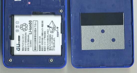
Click to zoom
Application Details
- Equipment Class
- TNE - Licensed Non-Broadcast Transmitter Held to Ear
- Date of Grant
- Dec 30, 2009
- Application Purpose
- Original Equipment
- Date of Application
- Dec 30, 2009
- Equipment Note
- Cellular Phone
- Frequency Range
- 824.70000000 - 848.37000000
- Company
- Sharp Corporation
- Country
- Japan
Documents & Files
Document Text
Text extracted from the exhibit documents filed with the FCC. Open a document above to read the original.
Users Manual
English Simple Manual Turning Power On and Off Turning Power On Hold down F for at least a few seconds. Turning Power Off Hold down F for at least a few seconds. Switching the Screen to English From the stand-by screen: Press c. z Press 3. z Press 6. z Press 2. Checking Your Own Phone Number and E-mail Address From the stand-by screen: Press c. z Press 0. Making and Answering a Call Making a Call From the stand-by screen: Enter the phone number you want to call. z Press N. To end a call: Press F. Light sensor Display Cursor key Address book key Mail/Character key Talk key Number keys Microphone Center key Application key EZ key Clear/Memo key Power/End key Camera lens Internal antennas Television antenna Earpiece Quick key Direct/Veil View key Mobile light/flash Internal au IC-Card Side key (Up) Side shutter key Battery pack/cover microSD memory card slot Side key (Down) Speaker Infrared port Charging terminals Side manner/clear key Strap eyelet Sub display External connection jack/cover Internal antennas Charging/Incoming indicator FeliCa mark c250_j_torisetsu.book 444 ページ 2009年12月3日 木曜日 午前11時41分 Answering a Call When the phone starts ringing, press N. To adjust the earpiece volume during a call: Use j. Storing and Recalling Address Book Entries Storing an Entry From the stand-by screen: Hold down & for at least one second. z Use j to select the item you want to edit. z Press c (Select). z Enter the data. z Press % (Reg). Recalling an Entry From the stand-by screen: Press & to display the Address Book screen. z Use s to select the tab for the record you want to recall. z Use j to select the name of the record. z Press c (Detail) to view the record in detail. Using the Camera (Movie and Snapshot) Recording a Movie Clip From the stand-by screen: Press c. z Use a to select “CAMERA”. z Press c (Select). z Select “Movie”. z Press c (Select). z Press c (Record) to start recording. z Press c (Stop) to stop recording. z Press c (Save) to store the movie. Press & () (Pause) during recording to pause recording. Press & () in the Movie mode to change to the Photo mode. Taking a Snapshot From the stand-by screen: Press c. z Use a to select “CAMERA”. z Press c (Select). z Select “Photo”. z Press c (Select). z Press c (Shoot) to take a snapshot. z Press c (Save) to store the photo. Press & () in the Photo mode to change to the Movie mode. Making an International Call Ex: To call 212-123- in the USA Other Handy Features Setting the Manner Mode From the stand-by screen: Hold down ( for at least one second. Repeat the above operation to disable the Manner Mode. Setting the Answer Memo (Voice Recording) From the stand-by screen: Hold down C for at least one second. Repeat the above operation to disable the Answer Memo. 001010 z 1 z 212 Area code International access codeCountry code (USA) z123z zN Number you want to call For inquiries, please contact au Customer Service Center (General Information) If you are calling from a landline phone: (toll free) If you are calling from an au mobile phone: (toll free) c250_j_torisetsu.book 445 ページ 2009年12月3日 木曜日 午前11時41分
External Photos
Model Name: CDMA SH006 FCC ID: APYHRO00112 Photo (External) 1/3 Model Name: CDMA SH006 FCC ID: APYHRO00112 Photo (External) 2/3 Model Name: CDMA SH006 FCC ID: APYHRO00112 Photo (External) 3/3
ID Label/Location Info
Model Name: CDMA SH006 FCC ID Location (On Spec Label) FCC ID:APYHRO00112 ○Spec Label ①,② Production Years & Month ③,④ Products Code ⑤,⑥ Production Number ⑦ Barcode of Production Number ⑧ Certification Number of TELEC ⑨ Approval Number of JATE ○Location Caution:Turn off power in aircrafts and hospitals. Don’t remove this label. Vendor:KDDI Corp.・Okinawa Cellular Corp. Manufacture/Applicant: SHARP Corp. ⑩ FCC ID: APYHRO00112
Internal Photos
Model Name: CDMA SH006 Photo (Internal) FCC ID: APYHRO00112 1/9 Model Name: CDMA SH006 Photo (Internal) FCC ID: APYHRO00112 2/9 Model Name: CDMA SH006 Photo (Internal) FCC ID: APYHRO00112 3/9 Model Name: CDMA SH006 Photo (Internal) FCC ID: APYHRO00112 4/9 Model Name: CDMA SH006 Photo (Internal) FCC ID: APYHRO00112 5/9 Model Name: CDMA SH006 Photo (Internal) FCC ID: APYHRO00112 6/9 Model Name: CDMA SH006 Photo (Internal) FCC ID: APYHRO00112 7/9 Model Name: CDMA SH006 Photo (Internal) FCC ID: APYHRO00112 8/9 Model Name: CDMA SH006 Photo (Internal) FCC ID: APYHRO00112 9/9
Internal Photos
Model Name: CDMA SH006 Photo (Antennas) FCC ID: APYHRO00112 Distance between CDMA Main antenna and Bluetooth antenna Bluetooth Antenna 1/4λ (printed on PCB) Sub Antenna (Receive Only) 0mm CDMA Main TX Antenna 1/1
RF Exposure Info
JAPAN QUALITY ASSURANCE ORGANIZATION Page 1 of 23 Technical document No. 23163-0701 JQA File No. : KL80090401 Issue Date : December 21, 2009 TEST REPORT (SAR EVALUATION) APPLICANT : Sharp Corporation, Communication Systems Group ADDRESS : 2-13-1, Iida, Hachihonmatsu, Higashi-Hiroshima City, Hiroshima, 739-0192, Japan PRODUCTS : Cellular Phone MODEL NO. : CDMA SH006 SERIAL NO. : SSHDL000916 FCC ID : APYHRO00112 TEST STANDARD : FCC/OET Bulletin 65 Supplement C (Edition 01-01) TESTING LOCATION : Japan Quality Assurance Organization KITA-KANSAI Testing Center 1-7-7, Ishimaru, Minoh-shi, Osaka 562-0027, Japan TEST RESULTS : Passed DATE OF TEST : December 3 ~ 4, 2009 This report must not used by the client to claim product endorsement by NVLAP or Junichi Wakamatsu NIST or any agency of the U.S. Government. Manager Japan Quality Assurance Organization KITA-KANSAI Testing Center Testing Dept. EMC Division NVLAP LAB CODE 200191-0 1-7-7, Ishimaru, Minoh-shi, Osaka 562-0027, Japan ● The measurement values stated in Test Report was made with traceable to National Institute of Advanced Industrial Science and Technology (AIST) of Japan, National Institute of Information and Communications Technology (NICT) of Japan , and Laboratory for EMF and Microwave Electronics at the Swiss Federal Institute of Technology (ETH) in Zürich, Switzerland. ● The applicable standard, testing condition and testing method which were used for the tests are based on the request of the applicant. ● The test results presented in this report relate only to the offered test sample. ● The contents of this test report cannot be used for the purposes, such as advertisement for consumers. ● This test report shall not be reproduced except in full without the written approval of JQA. JAPAN QUALITY ASSURANCE ORGANIZATION JQA File No. : KL80090401 Issue Date : December 21, 2009 Model No. : CDMA SH006 FCC ID : APYHRO00112 Standard : FCC/OET Bulletin 65 Supplement C (Edition 01-01) Page 2 of 23 Technical document No. 23163-0701 TABLE OF CONTENTS Page Documentation ................................................................................................................................................. 3 1 Test Regulation......................................................................................................................................3 2 Test Location..........................................................................................................................................3 3 Recognition of Test Laboratory.............................................................................................................3 4 Description of the Equipment Under Test...........................................................................................4 5 Measurement System Diagram............................................................................................................5 6 System Components..............................................................................................................................6 7 Measurement Process............................................................................................................................8 8 Measurement Uncertainties.................................................................................................................9 9 Equipment Under Test Modification..................................................................................................10 10 Responsible Party................................................................................................................................10 11 Deviation from Standard.....................................................................................................................10 12 Test Results..........................................................................................................................................11 13 Summary..............................................................................................................................................12 14 Test Arrangement................................................................................................................................13 15 Procedures used to Establish Test Signal..........................................................................................15 Appendix A: Test Data ................................................................................................................................... 16 Appendix B: Test Instruments....................................................................................................................... 22 Appendix C: Attachments .............................................................................................................................. 23 DEFINITIONS FOR ABBREVIATION AND SYMBOLS USED IN THIS TEST REPORT EUT : Equipment Under Test EMC : Electromagnetic Compatibility AE : Associated Equipment EMI : Electromagnetic Interference N/A : Not Applicable EMS : Electromagnetic Susceptibility N/T : Not Tested SAR : Specific Absorption Rate - indicates that the listed condition, standard or equipment is applicable for this report. - indicates that the listed condition, standard or equipment is not applicable for this report. JAPAN QUALITY ASSURANCE ORGANIZATION JQA File No. : KL80090401 Issue Date : December 21, 2009 Model No. : CDMA SH006 FCC ID : APYHRO00112 Standard : FCC/OET Bulletin 65 Supplement C (Edition 01-01) Page 3 of 23 Technical document No. 23163-0701 Documentation 1 Test Regulation Applied Standard : FCC/OET Bulletin 65 Supplement C (Edition 01-01) Evaluating Compliance with FCC Guidelines for Human Exposure to Radio- frequency Electromagnetic Fields Additional Information for Evaluating Compliance of Mobile and Portable Devices with FCC Limits for Human Exposure to Radiofrequency Emissions Test Procedure : FCC/OET Bulletin 65 Supplement C (Edition 01-01) IEEE Std.…
Text truncated - open the document above for the full version.
RF Exposure Info
Attachment 1 – System Validation Plots JAPAN QUALITY ASSURANCE ORGANIZATION Date/Time: 2009/12/03 10:53:15 Test Laboratory: JAPAN QUALITY ASSURANCE ORGANIZATION System Validation (Head 835 MHz) DUT: Dipole 835 MHz; Type: D835V2; Serial: 4d081 Communication System: CW; Frequency: 835 MHz;Duty Cycle: 1:1 Medium: HSL900 Medium parameters used: f = 835 MHz; σ = 0.898 mho/m; ε r = 41.3; ρ = 1000 kg/m 3 Phantom section: Flat Section Measurement Standard: DASY4 (High Precision Assessment) DASY4 Configuration: zProbe: ET3DV6 - SN1700; ConvF(6.05, 6.05, 6.05); Calibrated: 2009/10/22 zSensor-Surface: 4mm (Mechanical And Optical Surface Detection) zElectronics: DAE3 Sn508; Calibrated: 2009/11/09 zPhantom: SAM 1200; Type: QD 000 P40 CA; Serial: 1200 zMeasurement SW: DASY4, V4.7 Build 44; Postprocessing SW: SEMCAD, V1.8 Build 171 Antenna Input Power 250 mW/Area Scan (5x5x1): Measurement grid: dx=20mm, dy=20mm Maximum value of SAR (measured) = 2.52 mW/g Antenna Input Power 250 mW/Zoom Scan (5x5x7)/Cube 0: Measurement grid: dx=8mm, dy=8mm, dz=5mm Reference Value = 55.2 V/m; Power Drift = -0.012 dB Peak SAR (extrapolated) = 3.36 W/kg SAR(1 g) = 2.32 mW/g; SAR(10 g) = 1.53 mW/g Maximum value of SAR (measured) = 2.51 mW/g 0 dB = 2.51mW/g JAPAN QUALITY ASSURANCE ORGANIZATION Date/Time: 2009/12/04 10:38:21 Test Laboratory: JAPAN QUALITY ASSURANCE ORGANIZATION System Validation (Body 835 MHz) DUT: Dipole 835 MHz; Type: D835V2; Serial: 4d081 Communication System: CW; Frequency: 835 MHz;Duty Cycle: 1:1 Medium: M900 Medium parameters used: f = 835 MHz; σ = 0.943 mho/m; ε r = 54.3; ρ = 1000 kg/m 3 Phantom section: Flat Section Measurement Standard: DASY4 (High Precision Assessment) DASY4 Configuration: zProbe: ET3DV6 - SN1700; ConvF(5.89, 5.89, 5.89); Calibrated: 2009/10/22 zSensor-Surface: 4mm (Mechanical And Optical Surface Detection) zElectronics: DAE3 Sn508; Calibrated: 2009/11/09 zPhantom: SAM 1200; Type: QD 000 P40 CA; Serial: 1200 zMeasurement SW: DASY4, V4.7 Build 44; Postprocessing SW: SEMCAD, V1.8 Build 171 Antenna Input Power 250 mW/Area Scan (5x5x1): Measurement grid: dx=20mm, dy=20mm Maximum value of SAR (measured) = 2.64 mW/g Antenna Input Power 250 mW/Zoom Scan (5x5x7)/Cube 0: Measurement grid: dx=8mm, dy=8mm, dz=5mm Reference Value = 55.4 V/m; Power Drift = -0.009 dB Peak SAR (extrapolated) = 3.43 W/kg SAR(1 g) = 2.45 mW/g; SAR(10 g) = 1.63 mW/g 0 dB = 2.64mW/g JAPAN QUALITY ASSURANCE ORGANIZATION Attachment 2 – SAR Test Plots JAPAN QUALITY ASSURANCE ORGANIZATION Date/Time: 2009/12/03 20:19:22 Test Laboratory: JAPAN QUALITY ASSURANCE ORGANIZATION Left Head, Cheek/Touch 384ch (836.52MHz) DUT: Cellular Phone; Type: CDMA SH006; Serial: SSHDL000916 Communication System: CDMA2000 Cellular; Frequency: 836.52 MHz;Duty Cycle: 1:1 Medium: HSL900 Medium parameters used: f = 836.52 MHz; σ = 0.898 mho/m; ε r = 41.3; ρ = 1000 kg/m 3 Phantom section: Left Section Measurement Standard: DASY4 (High Precision Assessment) DASY4 Configuration: zProbe: ET3DV6 - SN1700; ConvF(6.05, 6.05, 6.05); Calibrated: 2009/10/22 zSensor-Surface: 4mm (Mechanical And Optical Surface Detection) zElectronics: DAE3 Sn508; Calibrated: 2009/11/09 zPhantom: SAM 1200; Type: QD 000 P40 CA; Serial: 1200 zMeasurement SW: DASY4, V4.7 Build 44; Postprocessing SW: SEMCAD, V1.8 Build 171 Cheek/Touch Position/Area Scan (11x6x1): Measurement grid: dx=15mm, dy=15mm Maximum value of SAR (measured) = 0.238 mW/g Cheek/Touch Position/Zoom Scan (5x5x7)/Cube 0: Measurement grid: dx=8mm, dy=8mm, dz=5mm Reference Value = 16.3 V/m; Power Drift = -0.052 dB Peak SAR (extrapolated) = 0.290 W/kg SAR(1 g) = 0.230 mW/g; SAR(10 g) = 0.166 mW/g Maximum value of SAR (measured) = 0.244 mW/g 0 dB = 0.244mW/g JAPAN QUALITY ASSURANCE ORGANIZATION Date/Time: 2009/12/03 21:35:15 Test Laboratory: JAPAN QUALITY ASSURANCE ORGANIZATION Left Head, Ear/Tilt 384ch (836.52MHz) DUT: Cellular Phone; Type: CDMA SH006; Serial: SSHDL000916 Communication System: CDMA2000 Cellular; Frequency: 836.52 MHz;Duty Cycle: 1:1 Medium: HSL900 Medium parameters used: f = 836.52 MHz; σ = 0.898 mho/m; ε r = 41.3; ρ = 1000 kg/m 3 Phantom section: Left Section Measurement Standard: DASY4 (High Precision Assessment) DASY4 Configuration: zProbe: ET3DV6 - SN1700; ConvF(6.05, 6.05, 6.05); Calibrated: 2009/10/22 zSensor-Surface: 4mm (Mechanical And Optical Surface Detection) zElectronics: DAE3 Sn508; Calibrated: 2009/11/09 zPhantom: SAM 1200; Type: QD 000 P40 CA; Serial: 1200 zMeasurement SW: DASY4, V4.7 Build 44; Postprocessing SW: SEMCAD, V1.8 Build 171 Ear/Tilt Position/Area Scan (11x6x1): Measurement grid: dx=15mm, dy=15mm Maximum value of SAR (measured) = 0.191 mW/g Ear/Tilt Position/Zoom Scan (5x5x7)/Cube 0: Measurement grid: dx=8mm, dy=8mm, dz=5mm Reference Value = 14.1 V/m; Power Drift = -0.021 dB Peak SAR (extrapolated) = 0.231 W/kg SAR(1 g) = 0.185 mW/g; SAR(10 g) = 0.140 mW/g Maximum value of SAR (measured) = 0.196 mW/g 0 dB = 0.196mW/g JAPAN QUALITY ASSURANCE ORGANIZATION Date/Time: 2009/12/03 22:29:46 Test Laboratory: JAPAN QUALITY ASSURANCE ORGANIZATION Right Head, Cheek/Touch 1013ch (824.70MHz) DUT: Cellular Phone; Type: CDMA SH006; Serial: SSHDL000916 Communication System: CDMA2000 Cellular; Frequency: 824.7 MHz;Duty Cycle: 1:1 Medium: HSL900 Medium parameters used: f = 824.7 MHz; σ = 0.891 mho/m; ε r = 41.4; ρ = 1000 kg/m 3 Phantom section: Right Section Measurement Standard: DASY4 (High Precision Assessment) DASY4 Configuration: zProbe: ET3DV6 - SN1700; ConvF(6.05, 6.05, 6.05); Calibrated: 2009/10/22 zSensor-Surface: 4mm (Mechanical And Optical Surface Detection) zElectronics: DAE3 Sn508; Calibrated: 2009/11/09 zPhantom: SAM 1200; Type: QD 000 P40 CA; Serial: 1200 zMeasurement SW: DASY4, V4.7 Build 44; Postprocessing SW: SEMCAD, V1.8 Build 171 Cheek/Touch Position/Area Scan (11x6x1): Measurement grid: dx=15mm, dy=15mm Maximum value of SAR (measured) = 0.217 mW/g Cheek/Touch Position/Zoom Scan (5x5x7)/Cube 0: Measurement grid: dx=8mm, dy=8mm, dz=5mm Reference Value = 16.4 V/m; Power Drif…
Text truncated - open the document above for the full version.
RF Exposure Info
SAR PROBE CALIBRATION (ET3DV6, SN 1700) Model No. : CDMA SH006 FCC ID : APYHRO00112 The following procedures are recommended for DUT measurements at 150 MHz to 3 GHz to minimize probe calibration and tissue dielectric parameter discrepancies. a) In general, DUT SAR measurements below 300 MHz should be within +/- 50 MHz of the probe calibration frequency. SEE ALSO ITEM c). b) At 300 MHz to 3 GHz, DUT measurements should be within +/- 100 MHz of the probe calibration frequency. SEE ALSO ITEM c). c) Measurements exceeding 50 % of these intervals, I.E., +/- 25 MHz, DUT f < 300 MHz, OR +/- 50 MHz, DUT f >/= 300 MHz, SHALL APPLY THE FOLLOWING additional steps: 1) When the actual tissue dielectric parameters used for probe calibration are available (careful about some probe manuf. list only nominal or range on calib. cert.), the differences for relative permittivity and conductivity between probe calibration and routine measurements should each be less than or equal to 5 % while also satisfying the required +/- 5 % tolerances in target dielectric parameters. JAPAN QUALITY ASSURANCE ORGANIZATION <Head 900 MHz> The test frequencies are properly matched as this is a cellular band. The probe calibration for permittivity and conductivity is within +/-5%, were the probe calibrated centre frequency at 900MHz has permittivity and conductivity of 41.5 and 0.97 respectively. At the probe extreme frequencies the following are true: at 800 MHz the permittivity and conductivity are 39.4 and 0.86 respectively. At 1000 MHz the permittivity and conductivity are 43.6 and 1.03 respectively. The probe was calibrated at these parameters in order to cover the frequency range 800 MHz to 1000 MHz. JAPAN QUALITY ASSURANCE ORGANIZATION <Body 900 MHz> The test frequencies are properly matched as this is a cellular band. The probe calibration for permittivity and conductivity is within +/-5%, were the probe calibrated centre frequency at 900MHz has permittivity and conductivity of 55.0 and 1.05 respectively. At the probe extreme frequencies the following are true: at 800 MHz the permittivity and conductivity are 52.3 and 0.92 respectively. At 1000 MHz the permittivity and conductivity are 57.8 and 1.10 respectively. The probe was calibrated at these parameters in order to cover the frequency range 800 MHz to 1000 MHz. JAPAN QUALITY ASSURANCE ORGANIZATION The target permittivity and conductivity at 835 MHz is 41.5 and 0.90 respectively which is within the calibrated range of the probe parameter. The following parameters are declared in the probe calibration certificate. JAPAN QUALITY ASSURANCE ORGANIZATION 2) When nominal tissue dielectric parameters are PROVIDED in the probe calibration data, the tissue dielectric parameters measured for routine measurements should be less than the target relative permittivity and higher than the target conductivity values, to minimize SAR underestimations. Otherwise, a thorough analysis of the effective frequency interval supported by the probe calibration and dielectric medium should be included in the SAR report to substantiate the test results – SEE ITEM d). Alternatively, the measured 1-g SAR may be compensated with respect to +5 % tolerances in relative permittivity and -5 % tolerances in conductivity, computed according to valid SAR sensitivity data, to reduce SAR underestimation and maintain conservativeness. d) When thorough analysis is required for the additional steps, the following SHALL ALSO BE ADDRESSED. These other items can contribute to additional SAR differences, especially when the probe calibration, tissue dielectric parameters and device test frequencies are misaligned. 1) The probe conversion factor and its frequency response, with respect to the tissue dielectric media used during probe calibration and routine measurements, should be examined to determine if the effective frequency interval is adequate for the intended measurements to satisfy protocol requirements. 2) Measurements within the required frequency interval should satisfy an expanded probe calibration uncertainty (k=2) less than or equal to 15 % for all measurement conditions. 3) When SAR is reported within 10 % of the SAR limit, differences in field conditions and effects of output power levels on signal modulation between probe calibration and routine measurements should be examined to determine probe calibration validity. 4) Probe isotropy should also be assessed by rotating the probe in 15 degree increments at the peak SAR location of the zoom scan and accounted for in the measurement uncertainty. The measured SAR values in the report are all below 10% of the SAR limit. The measurement within the required frequency interval satisfy an expanded probe calibration uncertainty (k=2) <= 15% for all measurement conditions. Please refer to SAR report for probe and dipole calibration certificates produce by the system manufacturer. As you can see we used the conductivity and permittivity parameters which are within +/- 5 % of the target values. JAPAN QUALITY ASSURANCE ORGANIZATION <cdma Cellular 850 MHz Head> Liquid Medium Freq. [MHz] Parameters Target Measured Deviation [%] Permitivity 41.6 41.39 -0.50 825.0 Conductivity0.90 0.891 -1.00 Permitivity 41.5 41.32 -0.43 835.0 Conductivity0.90 0.898 -0.22 Permitivity 41.5 41.24 -0.63 Head 845.0 Conductivity0.91 0.907 -0.33 Permittivity indicating +/-5 % tolerance 41.4 41.3 41.2 41.6 41.541.5 38.0 39.0 40.0 41.0 42.0 43.0 44.0 820.0825.0830.0835.0840.0845.0850.0855.0860.0 Frequency (MHz) Permittivity Measured Target Conductivity indicating +/-5 % tolerance 0.89 0.90 0.91 0.900.90 0.91 0.84 0.86 0.88 0.90 0.92 0.94 0.96 0.98 1.00 820.0825.0830.0835.0840.0845.0850.0855.0860.0 Frequency (MHz) Conductivity Measured Target JAPAN QUALITY ASSURANCE ORGANIZATION <cdma Cellular 850 MHz Body> Liquid Medium Freq. [MHz] Parameters Target Measured Deviation [%] Permitivity 55.2 54.35 -1.54 825.0 Conductivity0.97 0.933 -3.81 Permitivity 55.2 54.26 -1.70 835.0 Conductivity0.97 …
Text truncated - open the document above for the full version.
Test Report
JAPAN QUALITY ASSURANCE ORGANIZATION Page 1 of 43 JQA File No. : KL80090402 Issue Date : December 21, 2009 TEST REPORT APPLICANT : Sharp Corporation, Communication Systems Group ADDRESS : 2-13-1, Iida Hachihonmatsu, Higashi-Hiroshima City, Hiroshima, 739-0192, JAPAN PRODUCTS : Cellular Phone MODEL NO. : CDMA SH006 SERIAL NO. : SSHDL000914 FCC ID : APYHRO00112 TEST STANDARD : CFR 47 FCC Rules and Regulations Part 22 TESTING LOCATION : Japan Quality Assurance Organization KITA-KANSAI Testing Center 1-7-7, Ishimaru, Minoh-shi, Osaka 562-0027, Japan TEST RESULTS : Passed DATE OF TEST : November 20, 2009 - December 7, 2009 This report must not used by the client to claim product endorsement by NVLAP or Junichi Wakamatsu NIST or any agency of the U.S. Government. Manager Japan Quality Assurance Organization KITA-KANSAI Testing Center Testing Dept. EMC Division NVLAP LAB CODE 200191-0 1-7-7, Ishimaru, Minoh-shi, Osaka 562-0027, Japan ● The measurement values stated in Test Report was made with traceable to National Institute of Advanced Industrial Science and Technology (AIST) of Japan and National Institute of Information and Communications Technology (NICT) of Japan. ● The applicable standard, testing condition and testing method which were used for the tests are based on the request of the applicant. ● The test results presented in this report relate only to the offered test sample. ● The contents of this test report cannot be used for the purposes, such as advertisement for consumers. ● This test report shall not be reproduced except in full without the written approval of JQA. JAPAN QUALITY ASSURANCE ORGANIZATION JQA File No. : KL80090402 Issue Date : December 21, 2009 Model No. : CDMA SH006 FCC ID : APYHRO00112 Regulation : CFR 47 FCC Rules and Regulations Part 22 Page 2 of 43 TABLE OF CONTENTS Page Documentation ................................................................................................................................................. 3 1 Test Regulation......................................................................................................................................3 2 Test Location..........................................................................................................................................3 3 Recognition of Test Laboratory.............................................................................................................3 4 Description of the Equipment Under Test...........................................................................................4 5 Test Condition........................................................................................................................................5 6 Preliminary Test and Test Setup.........................................................................................................7 7 Equipment Under Test Modification..................................................................................................16 8 Responsible Party................................................................................................................................16 9 Deviation from Standard.....................................................................................................................16 10 Test Results..........................................................................................................................................17 11 Summary..............................................................................................................................................20 12 Operating Condition............................................................................................................................21 13 Test Configuration...............................................................................................................................21 14 Equipment Under Test Arrangement (Drawings)............................................................................22 Appendix A: Test Data ................................................................................................................................... 23 Appendix B: Test Arrangement (Photographs) ............................................................................................. 40 Appendix C: Test Instruments....................................................................................................................... 42 DEFINITIONS FOR ABBREVIATION AND SYMBOLS USED IN THIS TEST REPORT EUT : Equipment Under Test EMC : Electromagnetic Compatibility AE : Associated Equipment EMI : Electromagnetic Interference N/A : Not Applicable EMS : Electromagnetic Susceptibility N/T : Not Tested - indicates that the listed condition, standard or equipment is applicable for this report. - indicates that the listed condition, standard or equipment is not applicable for this report. JAPAN QUALITY ASSURANCE ORGANIZATION JQA File No. : KL80090402 Issue Date : December 21, 2009 Model No. : CDMA SH006 FCC ID : APYHRO00112 Regulation : CFR 47 FCC Rules and Regulations Part 22 Page 3 of 43 Documentation 1 Test Regulation Applied Standard : CFR 47 FCC Rules and Regulations Part 22 Subpart H – Cellular Radiotelephone Service Test Requirements : CFR 47 FCC Rules and Regulations Part 2 §2.1046, §2.1047, §2.1049, §2.1051, §2.1053, §2.1055 and §2.1057 Test Procedure : ANSI C63.4–2003, TIA/EIA–603-C-2004 2 Test Location KITA-KANSAI Testing Center 1-7-7, Ishimaru, Minoh-shi, Osaka 562-0027, Japan KAMEOKA EMC Branch 9-1, Ozaki, Inukanno, Nishibetsuin-cho, Kameoka-shi, Kyoto 621-0126, Japan 3 Recognition of Test Laboratory JQA KITA-KANSAI Testing Center Testing Department EMC Division is accredited under ISO/IEC 17025 by following accreditation bodies and the test facility of Testing Division is registered by the following bodies. VLAC Code : VLAC-001-2 (Effective through : April 3, 2010) NVLAP Lab Code : 200191-0 (Effective through : June…
Text truncated - open the document above for the full version.
Test Setup Photos
JAPAN QUALITY ASSURANCE ORGANIZATION JQA File No. : KL80090402 Issue Date : December 21, 2009 Model No. : CDMA SH006 FCC ID : APYHRO00112 Regulation : CFR 47 FCC Rules and Regulations Part 22 Page 40 of 43 Appendix B: Test Arrangement (Photographs) Radiated Emission – X-axis – – Y-axis – JAPAN QUALITY ASSURANCE ORGANIZATION JQA File No. : KL80090402 Issue Date : December 21, 2009 Model No. : CDMA SH006 FCC ID : APYHRO00112 Regulation : CFR 47 FCC Rules and Regulations Part 22 Page 41 of 43 – Z-axis – Photograph present configuration with maximum emission The EUT position of the maximum emission at Horizontal Polarization is X-axis. The EUT position of the maximum emission at Vertical Polarization is Z-axis.
Test Setup Photos
JAPAN QUALITY ASSURANCE ORGANIZATION JQA File No. : KL80090401 Issue Date : December 21, 2009 Model No. : CDMA SH006 FCC ID : APYHRO00112 Standard : FCC/OET Bulletin 65 Supplement C (Edition 01-01) Page 18 of 23 Technical document No. 23163-0701 A.3 SAR Measurement Data A.3.1 Left Head Cheek/Touch Position Ear/Tilt Position CDMA Cellular (Duty Cycle: 100 %, Crest Factor: 1) Date : December 3, 2009 Frequency Test Position Channel MHz Tx Power [dBm] Power Drift [dB] Limit [mW/g] SAR (1g) [mW/g] Tissue Temp. [°C] 1013 824.70 -- -- ** -- 384 836.52 23.40 -0.052 0.230 22.0 Cheek/Touch 779 848.37 -- -- 1.6 ** -- 1013 824.70 -- -- ** -- 384 836.52 23.40 -0.021 0.185 22.0 Ear/Tilt 779 848.37 -- -- 1.6 ** -- NOTES : 1. Depth of Liquid : 15.0 cm 2. Transmitter power was measured a…
Text truncated - open the document above for the full version.
Contact Information
Applicant
Taihei Ohtsuka(Division Manager, ESG & Q promotion div.)
Test Firm
Japan Quality Assurance Org. Tsuru EMC BranchKazuhisa Abe
Technical Specifications
| # | Rule Parts | Frequency Range | Power Output | Emission | Tolerance |
|---|---|---|---|---|---|
| 1 | 22H | 824.7 MHz - 848.37 MHz | 603.00 mW | 1M29F9W | 2.5000000000 ppm |
Other Applications from Sharp Corporation
APYHRO00343
Aug 17, 2026Smartphone
Equipment Class
DTS - Digital Transmission SystemAPYHRO00342
Jul 29, 2026Smart phone
Equipment Class
DXX - Part 15 Low Power Communication Device TransmitterAPYHRO00341
May 28, 2026Smart phone
Equipment Class
DTS - Digital Transmission SystemAPYHRO00340
Dec 01, 2025BT remote control
Equipment Class
DTS - Digital Transmission SystemAPYHRO00339
Sep 17, 2025Smart phone
Equipment Class
NII - Unlicensed National Information Infrastructure TX