APYHRO00121Cellular Phone
Sharp Corporation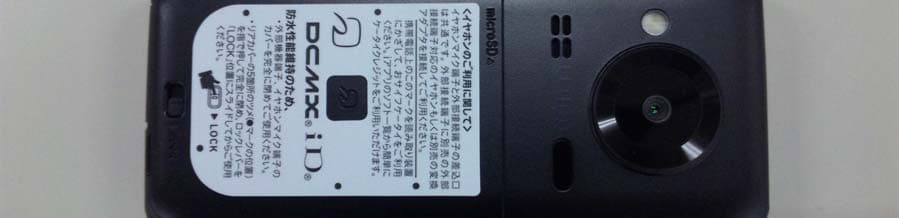
Click to zoom
Application Details
- Equipment Class
- DXX - Part 15 Low Power Communication Device Transmitter
- Date of Grant
- Apr 18, 2010
- Application Purpose
- Original Equipment
- Date of Application
- Apr 18, 2010
- Equipment Note
- Cellular Phone
- Frequency Range
- 13.56000000 - 13.56000000
- Company
- Sharp Corporation
- Country
- Japan
Documents & Files
Document Text
Text extracted from the exhibit documents filed with the FCC. Open a document above to read the original.
Users Manual
99 j07_2_dr40.fm [99/109]~~~~~~~~~~~~~~~~~~~~~~~ そ の 他 1Slide the back cover lever to unlock (1), hook a nail on the slot and remove the back cover (2) 2Pull out the tray straight (1). Set the UIM on the tray with the IC (gold) side turned down (2) and push the tray all the way in (3) 3Turn a recycle mark side up, match tabs and attach the battery pack 4Insert the tab of the top of the back cover into the FOMA terminal slot (1), insert it in the direction of the arrow (2) and securely push five tab areas down with both hands (3) 5Slide the back cover lever to lock Before Use Inserting UIM (FOMA card) and battery pack Slot Notch IC (gold) Tab 123 Tray Notch Tabs Turn off the power and insert the UIM/battery pack while holding the FOMA terminal with your both hands. Note that excessive force may damage the FOMA terminal, UIM and battery pack. The battery pack is not waterproof. Securely close the back cover. If not closed securely, the back cover may come off and the battery pack may fall out due to vibration. May damage the waterproof performance and allow water to seep. Back cover Lever dr40_uj.book 99 ページ 2010年3月23日 火曜日 午後12時30分 100 j07_2_dr40.fm [100/109]~~~~~~~~~~~~~~~~~~~~~~~ そ の 他 It is recommended that the accompanying desktop holder be used for charging to prevent water from seeping caused by forgetting to close the external connector terminal cover. The AC adapter and desktop holder are not waterproof. Never try to charge the battery pack when the FOMA terminal is wet. 1Insert the AC adapter into the connector terminal of the desktop holder 2Insert the AC adapter power plug into an outlet 3Place the FOMA terminal in the desktop holder in the direction of the arrow until it clicks (1) Charge start sound is heard, charging LED illuminates, and charging starts. 4Hold the desktop holder and lift the FOMA terminal out when charging is complete Charge end sound is heard and charging LED turns off when charging is complete. Charging Pull the AC adapter out of the outlet when left unused for a long period of time. When charge start sound is not heard or when charging LED does not illuminate, check that the FOMA terminal is placed securely in the desktop holder (except when terminal is turned off, manner mode is set or charge start sound is silent). Connector (Turn the side with the arrows up) FOMA AC Adapter 01/02 Charging LED 1 When placing the FOMA terminal in the desktop holder, be careful not to catch a strap, etc. dr40_uj.book 100 ページ 2010年3月23日 火曜日 午後12時30分 101 j07_2_dr40.fm [101/109]~~~~~~~~~~~~~~~~~~~~~~~ そ の 他 Key illustrations are examples and may look different from actual keys. Part Names and Functions 1Earpiece 2Air vent 3Main display 4i (,): i-mode/Operation guidance key 5m: Mail/Operation guidance key 6s: Start/Hands-free key 71 to 9, *, 0 and #: Dial/Character entry keys 8$: Multi/Quick search/VeilView key 9Mouthpiece/Microphone aSub camera bBrightness sensor cw&t&: Multi-guide key dC: Camera/TV/Operation guidance key ea: Phonebook/Operation guidance key fc (J): i-Channel/Clear key gH: Power/End key hy: MAP/GPS key iCharger termina jCalled/Charging LED k1Seg antenna lSub display mmicroSD Card slot n&: Side key oPicture Light pStrap hole qFOMA antenna rMain camera sSpeaker tInfrared port uBack cover vb mark wBack cover lever xExternal connector terminal dr40_uj.book 101 ページ 2010年3月23日 火曜日 午後12時30分 102 j07_2_dr40.fm [102/109]~~~~~~~~~~~~~~~~~~~~~~~ そ の 他 Main icons Turning power on 1H (for at least 2 seconds) Turning power off 1H (for at least 2 seconds) 1][SETTINGS]/[一般設定]/[Bilingual]/[English] The initial setting screen automatically appears when the power is turned on for the first time. Make the initial setting according to instructions on the screen. ※Terminal security code (four to eight digits) is set to [0000] by default but can be changed by user. Viewing Display/Icon Signal status bbbb (Strong b Weak) When [] appears, the handset is outside the service area or in a place with no signal. Battery level bbbbb (High b Low) i-mode/Full Browser i-appli GPS Ir communication i-mode mail/SMS/Area Mail received microSD Card 1Seg being recorded Record message Silent Vibrator Manner mode Public mode (Drive mode) IC card lock Icon display area Restriction Hands-free Alarm Music&Video Channel program reservation UIM error Self mode VeilView 3G ToruCa Information received Basic Operations Turning power on/off Changing screen display to English Making initial setting j07_2_dr40.fm 102 ページ 2010年3月23日 火曜日 午後2時32分 103 j07_2_dr40.fm [103/109]~~~~~~~~~~~~~~~~~~~~~~~ そ の 他 1]0 ※Operate in the character entry screen. Switching entry modes 1a/select the entry mode with w&/t& Switching upper/lower case 1Enter a character/* Deleting characters 1Move the cursor to the character and c To delete all characters: At the end of the message, c (for at least 1 second) Using phrases 1a (for at least 1 second)/select a phrase/t&/confirm the phrase/t& Entering pictograms/symbols 1i To switch between pictogram and Deco-mail pictogram: i To switch between single- and double-byte symbols: C 2Select a pictogram/symbol/t& Entering emoticons 1m (for at least 1 second)/select an emoticon/t& Character entry example Ex.) When entering “電話” 1a/[あ] with w& 24 (four times)/* (once)/0 (three times)/r&/0 (once) 3p& to move the cursor to the conversion candidates field 4Select “電話”/t& 1][SETTINGS]/[Snd/Vibrator/Manner]/[Select sound] 2Select an item/t& 3Select a ring tone/i 1][SETTINGS]/[Security]/[Change security code]/enter the current terminal security code/t& 2Enter the new terminal security code/t&/enter the new terminal security code again/t& 1][i-MODE]/[iMenu/Search]/[お客様サポート]/[各種設定 (確認・変 更・利用)]/[ネットワーク暗証番号変更] 1][i-MODE]/[iMenu/Search]/[English]/[Options]/[Change i-mode Password] 1][SETTINGS]/[Security]/[UIM Settings]/enter the terminal security code/t& 2Select the PIN1 or PIN2 code/t& 3Enter the current PIN code/t& 4Enter the new PIN code/t&/enter the new PIN code again/t& All lock 1][SETTINGS]/[S…
Text truncated - open the document above for the full version.
External Photos
Model Name:SH-08BPhoto(External)12th/April/2010 1 / 3 Model Name:SH-08BPhoto(External)12th/April/2010 2 / 3 Model Name:SH-08BPhoto(External)12th/April/2010 3 / 3
ID Label/Location Info
Model Name:SH-08B FCC ID: APYHRO00121 ○Spec Label Vendor : NTT DoCoMo ① Color Name ② Approval Number of JATE ③ Certifiction Number of TELEC ④ Production Years & Months ⑤ Bar Code of IMEI ⑥ IMEI (Production Serial Number) Manufucturer/Applicant : SHARP Corporation Caution : Turn off power in an aircraft. Don't remove this seal. ○Location Spec Label and Location 9/April/2010 FCC ID
Internal Photos
Model Name:SH-08BPhoto(Internal) 9th/April/2010 1 / 6 Model Name:SH-08BPhoto(Internal) 9th/April/2010 2 / 6 Model Name:SH-08BPhoto(Internal) 9th/April/2010 3 / 6 Model Name:SH-08BPhoto(Internal) 9th/April/2010 4 / 6 Model Name:SH-08BPhoto(Internal) 9th/April/2010 5 / 6 Model Name:SH-08BPhoto(Internal) 9th/April/2010 6 / 6
Test Report
JAPAN QUALITY ASSURANCE ORGANIZATION Page 1 of 27 JQA File No. : KL80090522 Issue Date : April 6, 2010 TEST REPORT APPLICANT : Sharp Corporation, Communication Systems Group ADDRESS : 2-13-1, Iida Hachihonmatsu, Higashi-Hiroshima City, Hiroshima, 739-0192, JAPAN PRODUCTS : Cellular Phone MODEL NO. : SH-08B SERIAL NO. : 004401112435207 FCC ID : APYHRO00121 TEST STANDARD : CFR 47 FCC Rules and Regulations Part 15 TESTING LOCATION : Japan Quality Assurance Organization KITA-KANSAI Testing Center 1-7-7, Ishimaru, Minoh-shi, Osaka 562-0027, Japan TEST RESULTS : Passed DATE OF TEST : March 29, 2010 - April 4, 2010 This report must not used by the client to claim product endorsement by NVLAP or Kousei Shibata NIST or any agency of the U.S. Government. Manager Japan Quality Assurance Organization KITA-KANSAI Testing Center Testing Dept. EMC Division NVLAP LAB CODE 200191-0 1-7-7, Ishimaru, Minoh-shi, Osaka 562-0027, Japan ● The measurement values stated in Test Report was made with traceable to National Institute of Advanced Industrial Science and Technology (AIST) of Japan and National Institute of Information and Communications Technology (NICT) of Japan. ● The applicable standard, testing condition and testing method which were used for the tests are based on the request of the applicant. ● The test results presented in this report relate only to the offered test sample. ● The contents of this test report cannot be used for the purposes, such as advertisement for consumers. ● This test report shall not be reproduced except in full without the written approval of JQA. JAPAN QUALITY ASSURANCE ORGANIZATION JQA File No. : KL80090522 Issue Date : April 6, 2010 Model No. : SH-08B FCC ID : APYHRO00121 Regulation : CFR 47 FCC Rules and Regulations Part 15 Page 2 of 27 TABLE OF CONTENTS Page Documentation ................................................................................................................................................. 3 1 Test Regulation......................................................................................................................................3 2 Test Location..........................................................................................................................................3 3 Recognition of Test Laboratory.............................................................................................................3 4 Description of the Equipment Under Test...........................................................................................4 5 Test Condition........................................................................................................................................5 6 Preliminary Test and Test Setup.........................................................................................................7 7 Equipment Under Test Modification..................................................................................................12 8 Responsible Party................................................................................................................................12 9 Deviation from Standard.....................................................................................................................12 10 Test Results..........................................................................................................................................13 11 Summary..............................................................................................................................................16 12 Operating Condition............................................................................................................................17 13 Test Configuration...............................................................................................................................17 14 Equipment Under Test Arrangement (Drawings)............................................................................17 Appendix A: Test Data ................................................................................................................................... 18 Appendix B: Test Arrangement (Photographs) ............................................................................................. 24 Appendix C: Test Instruments....................................................................................................................... 26 DEFINITIONS FOR ABBREVIATION AND SYMBOLS USED IN THIS TEST REPORT EUT : Equipment Under Test EMC : Electromagnetic Compatibility AE : Associated Equipment EMI : Electromagnetic Interference N/A : Not Applicable EMS : Electromagnetic Susceptibility N/T : Not Tested - indicates that the listed condition, standard or equipment is applicable for this report. - indicates that the listed condition, standard or equipment is not applicable for this report. JAPAN QUALITY ASSURANCE ORGANIZATION JQA File No. : KL80090522 Issue Date : April 6, 2010 Model No. : SH-08B FCC ID : APYHRO00121 Regulation : CFR 47 FCC Rules and Regulations Part 15 Page 3 of 27 Documentation 1 Test Regulation Applied Standard : CFR 47 FCC Rules and Regulations Part 15 Subpart C – Intentional Radiators Test Requirements : §15.225, §15.207 and §15.209 Test Procedure : ANSI C63.4–2003 2 Test Location KITA-KANSAI Testing Center 1-7-7, Ishimaru, Minoh-shi, Osaka 562-0027, Japan KAMEOKA EMC Branch 9-1, Ozaki, Inukanno, Nishibetsuin-cho, Kameoka-shi, Kyoto 621-0126, Japan 3 Recognition of Test Laboratory JQA KITA-KANSAI Testing Center Testing Department EMC Division is accredited under ISO/IEC 17025 by following accreditation bodies and the test facility of Testing Division is registered by the following bodies. VLAC Code : VLAC-001-2 (Effective through : March 30, 2012) NVLAP Lab Code : 200191-0 (Effective through : June 30, 2010) BSMI Recognition No. : SL2-IS-E-6006, SL2-IN-E-6006, SL2-AI-E-6006 (Effective through : September 14, 2010) VCCI Registrati…
Text truncated - open the document above for the full version.
Test Setup Photos
JAPAN QUALITY ASSURANCE ORGANIZATION JQA File No. : KL80090522 Issue Date : April 6, 2010 Model No. : SH-08B FCC ID : APYHRO00121 Regulation : CFR 47 FCC Rules and Regulations Part 15 Page 24 of 27 Appendix B: Test Arrangement (Photographs) B.1 AC Powerline Conducted Emission Not Applicable B.2 Radiated Emission – X-axis – – Y-axis – JAPAN QUALITY ASSURANCE ORGANIZATION JQA File No. : KL80090522 Issue Date : April 6, 2010 Model No. : SH-08B FCC ID : APYHRO00121 Regulation : CFR 47 FCC Rules and Regulations Part 15 Page 25 of 27 – Z-axis – Photograph present configuration with maximum emission The EUT position of the maximum emission is Z-axis.
Contact Information
Applicant
Taihei Ohtsuka(Deputy Division Manager, ESG & Q promotion unit)
Technical Contact
Sharp Electronics CorporationSteve Petruska
[email protected]201-529-9689
Sharp Plaza · Mahwah, New Jersey · United States
Non-Technical Contact
Sharp Electronics CorporationSteve Petruska
[email protected]201-529-9689
Test Firm
Japan Qlty. Assur. Org. Kitakansai Testing CenterHiroyuki Nakamura
Technical Specifications
| # | Rule Parts | Frequency Range | Power Output |
|---|---|---|---|
| 1 | 15C | 13.56 MHz - 13.56 MHz | - |
Other Applications from Sharp Corporation
APYHRO00343
Aug 17, 2026Smartphone
Equipment Class
DTS - Digital Transmission SystemAPYHRO00342
Jul 29, 2026Smart phone
Equipment Class
DXX - Part 15 Low Power Communication Device TransmitterAPYHRO00341
May 28, 2026Smart phone
Equipment Class
DTS - Digital Transmission SystemAPYHRO00340
Dec 01, 2025BT remote control
Equipment Class
DTS - Digital Transmission SystemAPYHRO00339
Sep 17, 2025Smart phone
Equipment Class
NII - Unlicensed National Information Infrastructure TX