APYHRO00141Mobile Terminal Equipment
Sharp Corporation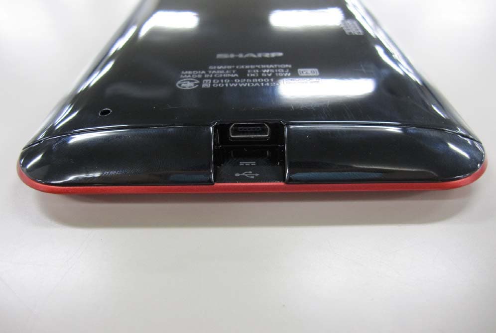
Click to zoom
Application Details
- Equipment Class
- DTS - Digital Transmission System
- Date of Grant
- Nov 16, 2010
- Application Purpose
- Original Equipment
- Date of Application
- Nov 15, 2010
- Equipment Note
- Mobile Terminal Equipment
- Frequency Range
- 2412.00000000 - 2462.00000000
- Company
- Sharp Corporation
- Country
- Japan
Documents & Files
Document Text
Text extracted from the exhibit documents filed with the FCC. Open a document above to read the original.
Users Manual
1 EB-W51GJ EB-WX1GJ Quick Tips Charge the product The product is not fully charged when you purchase it. Before using the product for the first time or when the battery has run low, charge the battery. ● Only use the specified AC adapter. Using an AC adapter other than the specified type may cause a fire or electric shock. ● If the product is not charged after the prescribed charging time has elapsed, stop charging. Continuing to charge the product may cause a fire or electric shock. 1. Insert the power plug of the AC adapter into a power socket. 2. Insert the connector of the AC adapter into the product's power/mini-USB connector. Power/mini-USB connector When charging starts, the battery indicator on the front side of the product () turns red. When the product is fully charged, the battery indicator turns off. 3. When charging is finished, remove the connector of the AC adapter. 4. Disconnect the AC adapter from the power socket. 2 Turn on/off the power Turn on the power 1. Press the power key. Rear side of product Turn off the power 1. Hold down the power key for 2 seconds. The menu is displayed. 2. Tap . 3. Tap [OK]. Setup STEP 1 : Configure wireless LAN settings Register information about the access point you will use. ● Users are liable for communication and connection charges required when using the wireless LAN function. ● These instructions cover the configuration procedure for an access point using AOSS. 1. Turn on the power by pressing the power key. 2. Tap []. 3. Tap []. 4. Tap []. Press the AOSS button on the access point device (the wireless LAN base station). 5. When the [] screen appears, tap [OK]. The ] screen appears. 3 STEP 2 : Register the product 1. On the [] screen, tap ]. After a few seconds, a user ID and password entry screen appears. 2. Enter your user ID and password, and tap ]. 3. Tap [OK]. Setup is now complete. FCC Notice ● This device complies with part 15 of the FCC Rules. Operation is subject to the following two conditions: (1) This device may not cause harmful interference, and (2) this device must accept any interference received, including interference that may cause undesired operation. ● Changes or modifications not expressly approved by the manufacturer responsible for compliance could void the user’s authority to operate the equipment. Information to User This equipment has been tested and found to comply with the limits of a Class B digital device, pursuant to Part 15 of the FCC Rules. These limits are designed to provide reasonable protection against harmful interference in a residential installation. This equipment generates, uses and can radiate radio frequency energy and, if not installed and used in accordance with the instructions, may cause harmful interference to radio communications. However, there is no guarantee that interference will not occur in a particular installation; if this equipment does cause harmful interference to radio or television reception, which can be determined by turning the equipment off and on, the user is encouraged to try to correct the interference by one or more of the following measures: 4 Printed in China 6060A1215302 10L IAC HI c 1. Reorient/relocate the receiving antenna. 2. Increase the separation between the equipment and receiver. 3. Connect the equipment into an outlet on a circuit different from that to which the receiver is connected. 4. Consult the dealer or an experienced radio/TV technician for help. FCC RF Exposure Information Your device is a radio transmitter and receiver. It is designed and manufactured not to exceed the emission limits for exposure to radio frequency (RF) energy set by the Federal Communications Commission of the U.S. Government. The guidelines are based on standards that were developed by independent scientific organizations through periodic and thorough evaluation of scientific studies. The standards include a substantial safety margin designed to assure the safety of all persons, regardless of age and health. The exposure standard for wireless devices employs a unit of measurement known as the Specific Absorption Rate, or SAR. The SAR limit set by the FCC is 1.6 W/kg.
Cover Letter(s)
カ{ μ叫んル.dJ){~
External Photos
AAC Adaapter (PV V-AC41) FCC ID: AAPYHRO000141
External Photos
Model Name: EB-W51GJ Model Name: EB-W51GJ FCC ID: APYHRO00141 FCC ID: APYHRO00141 Photo (External) 1 / 3 ページ Model Name: EB-W51GJ FCC ID: APYHRO00141 Photo (External) Photo (External) 2 / 3 ページ 3 / 3 ページ
ID Label/Location Info
FCC ID:APYHRO00141 EB-W51GJ FCC ID Location
Internal Photos
Model Name: EB-W51GJ Photo (Internal) FCC ID: APYHRO00141 1 / 6 ページ Model Name: EB-W51GJ Photo (Internal) FCC ID: APYHRO00141 2 / 6 ページ Model Name: EB-W51GJ Photo (Internal) FCC ID: APYHRO00141 3 / 6 ページ Model Name: EB-W51GJ FCC ID: APYHRO00141 Photo (Internal) RF Part 4 / 6 ページ Model Name: EB-W51GJ FCC ID: APYHRO00141 Photo (Internal) 5 / 6 ページ Model Name: EB-W51GJ Photo (Internal) FCC ID: APYHRO00141 6 / 6 ページ
Internal Photos
FCC ID:APYHRO00141 WirelessLANPartWireless LAN PartWireless LAN PartWireless LAN PartWireless LAN PartWireless LAN PartWireless LAN PartWireless LAN Part
Test Report
Test report No. : 31CE0252-HO-01-A Page : 2 of 42 Issued date : November 12, 2010 FCC ID : APYHRO00141 UL Japan, Inc. Head Office EMC Lab. 4383-326 Asama-cho, Ise-shi, Mie-ken 516-0021 JAPAN Telephone : +81 596 24 8116 Facsimile : +81 596 24 8124 CONTENTS PAGE SECTION 1: Customer information ......................................................................................................... 3 SECTION 2: Equipment under test (E.U.T.) ........................................................................................... 3 SECTION 3: Test specification, procedures & results ............................................................................ 4 SECTION 4: Operation of E.U.T. during testing .................................................................................... 7 SECTION 5: Conducted Emission ............................................................................................................ 9 SECTION 6: Radiated Spurious Emission ............................................................................................ 10 SECTION 7: Antenna Terminal Conducted Tests ................................................................................ 11 APPENDIX 1: Photographs of test setup ............................................................................................... 12 Conducted Emission ......................................................................................................................... 12 Radiated Spurious Emission ............................................................................................................. 13 Worst Case Position (Horizontal: X-axis/ Vertical:Y-axis) .............................................................. 14 APPENDIX 2: Data of EMI test .............................................................................................................. 15 Conducted Emission ......................................................................................................................... 15 6dB Bandwidth ................................................................................................................................. 19 Maximum Peak Output Power .......................................................................................................... 21 Radiated Spurious Emission ............................................................................................................. 23 The tested burst timing ...................................................................................................................... 31 Conducted Spurious Emission .......................................................................................................... 32 Conducted Emission Band Edge compliance ................................................................................... 38 Power Density ................................................................................................................................... 39 APPENDIX 3: Test instruments ............................................................................................................. 41 Test report No. : 31CE0252-HO-01-A Page : 3 of 42 Issued date : November 12, 2010 FCC ID : APYHRO00141 UL Japan, Inc. Head Office EMC Lab. 4383-326 Asama-cho, Ise-shi, Mie-ken 516-0021 JAPAN Telephone : +81 596 24 8116 Facsimile : +81 596 24 8124 SECTION 1: Customer information Company Name : Sharp Corporation Address : 2-13-1 Iida, Hachihonmatsu,Higashi-Hiroshima City,Hiroshima, 739- 0192 Japan Telephone Number : +81-82-420-1556 Facsimile Number : +81-82-420-1654 Contact Person : Chikashi Saizaki SECTION 2: Equipment under test (E.U.T.) 2.1 Identification of E.U.T. Type of Equipment : Mobile Terminal Equipment Model No. : EB-W51GJ Serial No. : Refer to Section 4, Clause 4.2 Rating : DC5.0V Receipt Date of Sample : November 5, 2010 Country of Mass-production : China Condition of EUT : Production prototype (Not for Sale: This sample is equivalent to mass-produced items.) Modification of EUT : No Modification by the test lab 2.2 Product Description Model No: EB-W51GJ (referred to as the EUT in this report) is the Mobile Terminal Equipment. General Specification Clock frequency in the system : CPU: 800MHz Radio Specification Radio Type : Transceiver Frequency of Operation : 2412-2462MHz Modulation : DSSS Power Supply (radio part input) : DC 3.3V / DC 1.8V Antenna type : Chip Antenna Antenna Gain : Max 1.93dBi Test report No. : 31CE0252-HO-01-A Page : 4 of 42 Issued date : November 12, 2010 FCC ID : APYHRO00141 UL Japan, Inc. Head Office EMC Lab. 4383-326 Asama-cho, Ise-shi, Mie-ken 516-0021 JAPAN Telephone : +81 596 24 8116 Facsimile : +81 596 24 8124 SECTION 3: Test specification, procedures & results 3.1 Test Specification Test Specification : FCC Part 15 Subpart C: 2010, final revised on October 13, 2010 Title : FCC 47CFR Part15 Radio Frequency Device Subpart C Intentional Radiators Section 15.207 Conducted limits Section 15.247 Operation within the bands 902-928MHz, 2400-2483.5MHz, and 5725-5850MHz 3.2 Procedures and results Item Test Procedure Specification Worst margin Results Remarks Conducted Emission ANSI C63.4:2003 7. AC powerline Conducted Emission measurements Section 15.207 QP 20.0dB (0.59160MHz, L) AV 18.1dB (0.52983MHz, N) (0.53002MHz, L) Complied - 6dB Bandwidth "Guidance on Measurement of Digital Transmission Systems Operating under Section15.247" Section 15.247(a)(2) See data. Complied Conducted Maximum Peak Output Power "Guidance on Measurement of Digital Transmission Systems Operating under Section15.247" Section 15.247(b)(3) Complied Conducted Power Density "Guidance on Measurement of Digital Transmission Systems Operating under Section15.247" Section 15.247 (e) Complied Conducted Spurious Emission Restricted Band Edges "Guidance on Measurement of Digital Transmission Systems Operating under Section15.247" Section15.247(d) [Tx] 1.1dB 2483.5MHz, PK, Hori,Vert. Complied Con…
Text truncated - open the document above for the full version.
Test Report
Test report No. : 31CE0252-HO-01-A Page : 15 of 42 Issued date : November 12, 2010 FCC ID : APYHRO00141 UL Japan, Inc. Head Office EMC Lab. 4383-326 Asama-cho, Ise-shi, Mie-ken 516-0021 JAPAN Telephone : +81 596 24 8116 Facsimile : +81 596 24 8124 APPENDIX 2: Data of EMI test Conducted Emission DATA OF CONDUCTED EMISSION TEST UL Japan, Inc. Head Office EMC Lab. No.4 Semi Anechoic Chamber Company : SHARP CORPORATION Report No. : 31CE0252-HO-01 Kind of EUT : Mobile Terminal Equipment Power : AC 120V / 60Hz Model No. : EB-W51GJ Temp./Humi. : 21deg.C. / 40% Serial No. : 3 Engineer : Tomohisa Nakagawa Mode / Remarks : Tx 11b 2412MHz, 11Mbps LIMIT : FCC15.207 QP FCC15.207 AV CHART:WITH FACTOR,Peak hold data. CALCULATION:RESULT[dBuV]=READING[dBuV]+C.F[dB](LISN LOSS+CABLE LOSS) Except for the above table : adequate margin data below the limits. Frequency[Hz] [dBuV]<< QP/AV DATA >> L:QP:AV N:QP:AV .15M30M.2M.3M.5M.7M1M2M3M5M7M10M20M 0 10 20 30 40 50 60 70 80 Frequency Reading LevelReading LevelCorr.ResultsResultsLimitLimitMarginMargin PhaseComment Frequency QPAVFactorQPAVQPAVQPAVPhaseComment [MHz][dBuV][dBuV][dB][dBuV][dBuV][dBuV][dBuV][dB][dB] PhaseComment 0.1534824.813.213.238.026.465.855.827.829.4N 0.5930521.78.313.435.121.756.046.020.924.3N 1.5786222.411.613.435.825.056.046.020.221.0N 3.1639820.113.113.733.826.856.046.022.219.2N 5.6453915.49.014.329.723.360.050.030.326.7N 13.619167.0-2.015.622.613.660.050.037.436.4N 0.1526124.814.313.238.027.565.955.927.928.4L 0.5916022.69.913.436.023.356.046.020.022.7L 1.5876917.28.713.430.622.156.046.025.423.9L 3.1588321.011.113.734.724.856.046.021.321.2L 5.5275020.611.514.234.825.760.050.025.224.3L 13.541308.52.015.624.117.660.050.035.932.4L Test report No. : 31CE0252-HO-01-A Page : 16 of 42 Issued date : November 12, 2010 FCC ID : APYHRO00141 UL Japan, Inc. Head Office EMC Lab. 4383-326 Asama-cho, Ise-shi, Mie-ken 516-0021 JAPAN Telephone : +81 596 24 8116 Facsimile : +81 596 24 8124 Conducted Emission Test place Head Office EMC Lab. No.4 Semi Anechoic Chamber Report No. 31CE0252-HO-01 Date 11/07/2010 Temperature/ Humidity 21 deg.C./ 40% Engineer Tomohisa Nakagawa Mode 11b Tx 2412MHz 2437MHz 2462MHz Y scale [dBuV] Chart N L Test report No. : 31CE0252-HO-01-A Page : 17 of 42 Issued date : November 12, 2010 FCC ID : APYHRO00141 UL Japan, Inc. Head Office EMC Lab. 4383-326 Asama-cho, Ise-shi, Mie-ken 516-0021 JAPAN Telephone : +81 596 24 8116 Facsimile : +81 596 24 8124 Conducted Emission DATA OF CONDUCTED EMISSION TEST UL Japan, Inc. Head Office EMC Lab. No.4 Semi Anechoic Chamber Company : SHARP CORPORATION Report No. : 31CE0252-HO-01 Kind of EUT : Mobile Terminal Equipment Power : AC 120V / 60Hz Model No. : EB-W51GJ Temp./Humi. : 21deg.C. / 40% Serial No. : 3 Engineer : Tomohisa Nakagawa Mode / Remarks : Tx 11g 2412MHz, 6Mbps LIMIT : FCC15.207 QP FCC15.207 AV CHART:WITH FACTOR,Peak hold data. CALCULATION:RESULT[dBuV]=READING[dBuV]+C.F[dB](LISN LOSS+CABLE LOSS) Except for the above table : adequate margin data below the limits. Frequency[Hz] [dBuV]<< QP/AV DATA >> L:QP:AV N:QP:AV .15M30M.2M.3M.5M.7M1M2M3M5M7M10M20M 0 10 20 30 40 50 60 70 80 Frequency Reading LevelReading LevelCorr.ResultsResultsLimitLimitMarginMargin PhaseComment Frequency QPAVFactorQPAVQPAVQPAVPhaseComment [MHz][dBuV][dBuV][dB][dBuV][dBuV][dBuV][dBuV][dB][dB] PhaseComment 0.1500024.48.013.237.621.266.056.028.434.8N 0.5298320.714.513.434.127.956.046.021.918.1N 1.5485016.610.413.430.023.856.046.026.022.2N 3.3314514.27.913.727.921.656.046.028.124.4N 5.4823013.76.214.227.920.460.050.032.129.6N 13.218166.0-3.015.621.612.660.050.038.437.4N 0.1597324.19.613.237.322.865.555.528.232.7L 0.5300221.114.513.434.527.956.046.021.518.1L 1.6402017.88.513.431.221.956.046.024.824.1L 3.4341218.96.913.732.620.656.046.023.425.4L 5.3791618.511.314.232.725.560.050.027.324.5L 13.528308.71.615.624.317.260.050.035.732.8L Test report No. : 31CE0252-HO-01-A Page : 18 of 42 Issued date : November 12, 2010 FCC ID : APYHRO00141 UL Japan, Inc. Head Office EMC Lab. 4383-326 Asama-cho, Ise-shi, Mie-ken 516-0021 JAPAN Telephone : +81 596 24 8116 Facsimile : +81 596 24 8124 Conducted Emission Test place Head Office EMC Lab. No.4 Semi Anechoic Chamber Report No. 31CE0252-HO-01 Date 11/07/2010 Temperature/ Humidity 21 deg.C./ 40% Engineer Tomohisa Nakagawa Mode 11g Tx 2412MHz 2437MHz 2462MHz Y scale [dBuV] Chart N L Test report No. : 31CE0252-HO-01-A Page : 19 of 42 Issued date : November 12, 2010 FCC ID : APYHRO00141 UL Japan, Inc. Head Office EMC Lab. 4383-326 Asama-cho, Ise-shi, Mie-ken 516-0021 JAPAN Telephone : +81 596 24 8116 Facsimile : +81 596 24 8124 6dB Bandwidth Test place Head Office EMC Lab. No.6 Measurement Room Report No. 31CE0252-HO-01 Date 11/05/2010 Temperature/ Humidity 21 deg.C./ 46% Engineer Hisayoshi Sato Mode 11b/g Tx 11b Frequency 6dB Bandwidth Limit [MHz] [MHz] [kHz] 2412 9.607 >500 2437 9.583 >500 2462 9.615 >500 11g Frequency 6dB Bandwidth Limit [MHz] [MHz] [kHz] 2412 15.603 >500 2437 15.780 >500 2462 15.433 >500 Test report No. : 31CE0252-HO-01-A Page : 20 of 42 Issued date : November 12, 2010 FCC ID : APYHRO00141 UL Japan, Inc. Head Office EMC Lab. 4383-326 Asama-cho, Ise-shi, Mie-ken 516-0021 JAPAN Telephone : +81 596 24 8116 Facsimile : +81 596 24 8124 6dB Bandwidth 11b 11g 2412MHz 2412MHz 2437MHz 2437MHz 2462MHz 2462MHz Test report No. : 31CE0252-HO-01-A Page : 21 of 42 Issued date : November 12, 2010 FCC ID : APYHRO00141 UL Japan, Inc. Head Office EMC Lab. 4383-326 Asama-cho, Ise-shi, Mie-ken 516-0021 JAPAN Telephone : +81 596 24 8116 Facsimile : +81 596 24 8124 Maximum Peak Output Power Test place Head Office EMC Lab. No.6 Measurement Room Report No. 31CE0252-HO-01 Date 11/05/2010 Temperature/ Humidity 21 deg.C./ 46% Engineer Hisayoshi Sato Mode 11b Tx Freq.ReadingCableAtten.Margin Loss [MHz][dBm][dB][dB][dBm][mW][dBm][mW][dB] 24126.452.6710.0819.2083.0830.00100010.81 24376.632.5110.0819.2283.5030.00100010.78 24626.332.4410.0818.8576.6730.00100011.15 Sample Calculation: Result = Reading + Cabl…
Text truncated - open the document above for the full version.
Test Report
Test report No. : 31CE0252-HO-01-E Page : 35 of 66 FCC ID : APYHRO00141 Issued date : November 12, 2010 UL Japan, Inc. Head Office EMC Lab. 4383-326 Asama-cho, Ise-shi, Mie-ken 516-0021 JAPAN Telephone : +81 596 24 8116 Facsimile : +81 596 24 8124 APPENDIX 3 : Test instruments Test report No. : 31CE0252-HO-01-E Page : 36 of 66 FCC ID : APYHRO00141 Issued date : November 12, 2010 UL Japan, Inc. Head Office EMC Lab. 4383-326 Asama-cho, Ise-shi, Mie-ken 516-0021 JAPAN Telephone : +81 596 24 8116 Facsimile : +81 596 24 8124 1. Equipment used Control No. Instrument Manufacturer Model No Serial No Test Item Calibration Date * Interval(month) MPM-08 Power Meter Anritsu ML2495A 6K00003338 Power Measurement 2010/09/10 * 12 MPSE-11 Power sensor Anritsu MA2411B 011737 Power Measurement 2010/09/10 * 12 MAT-20 Attenuator(10dB)(ab ove1GHz) HIROSE ELECTRIC CO.,LTD. AT-110 - Power Measurement 2010/01/26 * 12 MCC-66 Microwave Cable 1G-40GHz Schner SUCOFLEX- 102 28636/2 Power Measurement 2010/04/27 * 12 MPM-01 Power Meter Agilent E4417A GB41290639 SAR 2010/02/16 * 12 MPSE-01 Power Sensor Agilent E9300B US40010300 SAR 2010/02/11 * 12 MPSE-03 Power sensor Agilent E9327A US40440576 SAR 2010/02/19 * 12 MAT-15 Attenuator(30dB) Agilent 8498A US40010300 SAR 2010/02/24 * 12 MSG-10 Signal Generator Agilent N5181A MY47421098 SAR 2010/09/08 * 12 MRFA-08 Pre Amplifier TSJ TCBP0206 - SAR 2010/03/19 * 12 MHDC-12 Dual Directional Coupler Hewlett Packard 772D 2839A0016 SAR Pre Check MNA-01 Network Analyzer Agilent/HP E8358A US41080381 SAR 2010/08/19 * 12 MRENT-85 Dielectric probe kit Agilent 85070E - SAR Pre Check MNCK-01 Type N Calibration Kit Agilent 85032F MY41495257 SAR 2010/08/10 * 12 MPB-03 Dosimetric E-Field Probe Schmid&Partner Engineering AG EX3DV3 3507 SAR 2010/02/19 * 12 MDAE-01 Data Acquisition Electronics Schmid&Partner Engineering AG DAE3 V1 509 SAR 2010/07/07 * 12 COTS-MSAR-01 DASY4 Schmid&Partner Engineering AG DASY4 V4.7 Build80 - SAR - COTS-MSAR-02 S-Parameter Network Analyzer Agilent - - SAR - MDA-07 Dipole Antenna Schmid&Partner Engineering AG D2450V2 713 SAR 2010/09/06 * 24 MPF-02 2mmOval Flat Phantom ERI 4.0 Schmid&Partner Engineering AG QD VA 001B (ERI4.0) 1045 SAR Pre Check MOS-05 Thermo-Hygrometer Custom CTH-190 810201 SAR 2010/04/21 * 12 MOS-10 Digtal thermometer HANNA Checktemp-2 MOS-10 SAR 2010/08/02 * 12 MBM-13 Barometer Sunoh SBR121 837 SAR 2008/03/14 * 36 Body2450MHz Daily check Target value ± 5% SAR room Daily check Ambient Noise<0.012W/kg The expiration date of the calibration is the end of the expired month. As for some calibrations performed after the tested dates, those test equipment have been controlled by means of an unbroken chains of calibrations Test report No. : 31CE0252-HO-01-E Page : 37 of 66 FCC ID : APYHRO00141 Issued date : November 12, 2010 UL Japan, Inc. Head Office EMC Lab. 4383-326 Asama-cho, Ise-shi, Mie-ken 516-0021 JAPAN Telephone : +81 596 24 8116 Facsimile : +81 596 24 8124 2. Dosimetry assessment setup These measurements were performed with the automated near-field scanning system DASY4 from Schmid & Partner Engineering AG (SPEAG). The system is based on a high precision robot (working range greater than 0.9 m), which positions the probes with a positional repeatability of better than +/- 0.02 mm. Special E- and H-field probes have been developed for measurements close to material discontinuity, the sensors of which are directly loaded with a Schottky diode and connected via highly resistive lines to the data acquisition unit. The SAR measurements were conducted with the dosimetry probe EX3DV3, SN: 3507(manufactured by SPEAG), designed in the classical triangular configuration and optimized for dosimetric evaluation. The probe has been calibrated according to the procedure described in [2] with accuracy of better than +/-10%. The spherical isotropy was evaluated with the procedure described in [3] and found to be better than +/-0.25 dB. The phantom used was the SAM Twin Phantom as described in FCC supplement C, IEEE P1528 and CENELEC EN50361. Test report No. : 31CE0252-HO-01-E Page : 38 of 66 FCC ID : APYHRO00141 Issued date : November 12, 2010 UL Japan, Inc. Head Office EMC Lab. 4383-326 Asama-cho, Ise-shi, Mie-ken 516-0021 JAPAN Telephone : +81 596 24 8116 Facsimile : +81 596 24 8124 3. Configuration and peripherals The DASY4 system for performing compliance tests consist of the following items: 1. A standard high precision 6-axis robot (Stäubli RX family) with controller and software. An arm extension for accommodating the data acquisition electronics (DAE). 2. A dosimetric probe, i.e., an isotropic E-field probe optimized and calibrated for usage in tissue simulating liquid. The probe is equipped with an optical surface detector system. 3. A data acquisition electronic (DAE), which performs the signal amplification, signal multiplexing, AD-conversion, offset measurements, mechanical surface detection, collision detection, etc. The unit is battery powered with standard or rechargeable batteries. The signal is optically transmitted to the EOC. 4. The Electro-optical converter (EOC) performs the conversion between optical and electrical of the signals for the digital communication to the DAE and for the analog signal from the optical surface detection. The EOC is connected to the measurement server. 5. The function of the measurement server is to perform the time critical tasks such as signal filtering, control of the robot operation and fast movement interrupts. 6. A probe alignment unit which improves the (absolute) accuracy of the probe positioning. 7. A computer operating Windows 2000. 8. DASY4 software. 9. Remote control with teaches pendant and additional circuitry for robot safety such as warning lamps, etc. 10. The 2mm Flat phantom ERI4.0 11. The device holder for handheld mobile phones. 12. Tissue simulating liquid mixed according to the given recipes. 13. Validation dipole kits allowing to validate the proper functioning of the system. Test report No. :…
Text truncated - open the document above for the full version.
Test Report
Test report No. : 31CE0252-HO-01-E Page : 24 of 66 FCC ID : APYHRO00141 Issued date : November 12, 2010 UL Japan, Inc. Head Office EMC Lab. 4383-326 Asama-cho, Ise-shi, Mie-ken 516-0021 JAPAN Telephone : +81 596 24 8116 Facsimile : +81 596 24 8124 APPENDIX 2 : SAR Measurement data Test report No. : 31CE0252-HO-01-E Page : 25 of 66 FCC ID : APYHRO00141 Issued date : November 12, 2010 UL Japan, Inc. Head Office EMC Lab. 4383-326 Asama-cho, Ise-shi, Mie-ken 516-0021 JAPAN Telephone : +81 596 24 8116 Facsimile : +81 596 24 8124 1. Evaluation procedure The evaluation was performed with the following procedure: Step 1: Measurement of the E-field at a fixed location above the ear point or central position of flat phantom was used as a reference value for assessing the power drop. Step 2: The SAR distribution at the exposed side of head or body position was measured at a distance of each device from the inner surface of the shell. The area covered the entire dimension of the antenna of EUT and the horizontal grid spacing was 15 mm x 15 mm . Based on these data, the area of the maximum absorption was determined by spline interpolation. Step 3: Around this point found in the Step 2 (area scan), a volume of 30mm x 30mm x 30mm was assessed by measuring 7 x 7 x 7 points for IEEE802.11b (2.4G) And for any secondary peaks found in the Step2 which are within 2dB of maximum peak (level more than ambient noise (>0.012 W/kg)) and not with this Step3 (Zoom scan) is repeated. On the basis of this data set, the spatial peak SAR value was evaluated under the following procedure: (1). The data at the surface were extrapolated, since the center of the dipoles is 1mm away from the tip of the probe and the distance between the surface and the lowest measuring point is 1mm. Therefore minimum distance of probe sensor from surface was set to the 2mm. The extrapolation was based on a least square algorithm [4]. A polynomial of the fourth order was calculated through the points in z-axes. This polynomial was then used to evaluate the points between the surface and the probe tip. (2). The maximum interpolated value was searched with a straightforward algorithm. Around this maximum the SAR values averaged over the spatial volumes (1 g or 10 g) were computed by the 3D-Spline interpolation algorithm. The 3D-Spline is composed of three one-dimensional splines with the “Not a knot"-condition (in x, y and z-directions) [4], [5]. The volume was integrated with the trapezoidal-algorithm. One thousand points (10 x 10 x 10) were interpolated to calculate the average. (3). All neighboring volumes were evaluated until no neighboring volume with a higher average value was found. Step 4: Re-measurement of the E-field at the same location as in Step 1. Test report No. : 31CE0252-HO-01-E Page : 26 of 66 FCC ID : APYHRO00141 Issued date : November 12, 2010 UL Japan, Inc. Head Office EMC Lab. 4383-326 Asama-cho, Ise-shi, Mie-ken 516-0021 JAPAN Telephone : +81 596 24 8116 Facsimile : +81 596 24 8124 2. Measurement data (Body SAR) EB-W51GJ/Body/Rear surface/11b DBPSK 1Mbps/2437MHz Duty Cycle: 1:1 Medium: M2450 Medium parameters used: f = 2450 MHz; σ = 1.98 mho/m; ε r = 50.4; ρ = 1000 kg/m 3 Phantom section: Flat Section DASY4 Configuration: - Probe: EX3DV3 - SN3507; ConvF(8.11, 8.11, 8.11); Calibrated: 2010/02/19 - Sensor-Surface: 2mm (Mechanical Surface Detection) - Phantom: Flat Phantom ELI4.0 - Measurement SW: DASY4, V4.7 Build 80; Postprocessing SW: SEMCAD, V1.8 Build 186 Area Scan (81x131x1): Measurement grid: dx=15mm, dy=15mm Maximum value of SAR (interpolated) = 1.83 mW/g Zoom Scan (7x7x7)/Cube 0: Measurement grid: dx=5mm, dy=5mm, dz=5mm Reference Value = 4.62 V/m; Power Drift = 0.144 dB Peak SAR (extrapolated) = 2.65 W/kg SAR(1 g) = 0.916 mW/g; SAR(10 g) = 0.355 mW/g Maximum value of SAR (measured) = 1.57 mW/g Test Date = 11/08/10 Ambient Temperature = 24.8 degree.C. Liquid Temperature = Before 24.0 degree.C. , After 24.0 degree.C. Test report No. : 31CE0252-HO-01-E Page : 27 of 66 FCC ID : APYHRO00141 Issued date : November 12, 2010 UL Japan, Inc. Head Office EMC Lab. 4383-326 Asama-cho, Ise-shi, Mie-ken 516-0021 JAPAN Telephone : +81 596 24 8116 Facsimile : +81 596 24 8124 EB-W51GJ/Body/Rear surface/11b CCK 11Mbps/2437MHz Duty Cycle: 1:1 Medium: M2450 Medium parameters used: f = 2450 MHz; σ = 1.98 mho/m; ε r = 50.4; ρ = 1000 kg/m 3 Phantom section: Flat Section DASY4 Configuration: - Probe: EX3DV3 - SN3507; ConvF(8.11, 8.11, 8.11); Calibrated: 2010/02/19 - Sensor-Surface: 2mm (Mechanical Surface Detection) - Phantom: Flat Phantom ELI4.0 - Measurement SW: DASY4, V4.7 Build 80; Postprocessing SW: SEMCAD, V1.8 Build 186 Area Scan (81x131x1): Measurement grid: dx=15mm, dy=15mm Maximum value of SAR (interpolated) = 2.22 mW/g Zoom Scan (7x7x7)/Cube 0: Measurement grid: dx=5mm, dy=5mm, dz=5mm Reference Value = 4.11 V/m; Power Drift = 0.204 dB Peak SAR (extrapolated) = 2.52 W/kg SAR(1 g) = 0.895 mW/g; SAR(10 g) = 0.348 mW/g Maximum value of SAR (measured) = 1.58 mW/g Test Date = 11/08/10 Ambient Temperature = 24.8 degree.C. Liquid Temperature = Before 24.0 degree.C. , After 24.0 degree.C. Test report No. : 31CE0252-HO-01-E Page : 28 of 66 FCC ID : APYHRO00141 Issued date : November 12, 2010 UL Japan, Inc. Head Office EMC Lab. 4383-326 Asama-cho, Ise-shi, Mie-ken 516-0021 JAPAN Telephone : +81 596 24 8116 Facsimile : +81 596 24 8124 EB-W51GJ/Body/Right edge/11b DBPSK 1Mbps/2437MHz Duty Cycle: 1:1 Medium: M2450 Medium parameters used: f = 2450 MHz; σ = 1.98 mho/m; ε r = 50.4; ρ = 1000 kg/m 3 Phantom section: Flat Section DASY4 Configuration: - Probe: EX3DV3 - SN3507; ConvF(8.11, 8.11, 8.11); Calibrated: 2010/02/19 - Sensor-Surface: 2mm (Mechanical Surface Detection) - Phantom: Flat Phantom ELI4.0 - Measurement SW: DASY4, V4.7 Build 80; Postprocessing SW: SEMCAD, V1.8 Build 186 Area Scan (81x131x1): Measurement grid: dx=15mm, dy=15mm Maximum value of SAR (interpolated) = 0.837 mW/g Zoom Scan (7x7x7)/Cube 0: Measurement grid: dx=5mm, dy=5mm,…
Text truncated - open the document above for the full version.
Test Report
Test report No. : 31CE0252-HO-01-E Page : 2 of 66 FCC ID : APYHRO00141 Issued date : November 12, 2010 UL Japan, Inc. Head Office EMC Lab. 4383-326 Asama-cho, Ise-shi, Mie-ken 516-0021 JAPAN Telephone : +81 596 24 8116 Facsimile : +81 596 24 8124 CONTENTS PAGE SECTION 1: Customer information ................................................................................................. 3 SECTION 2: Equipment under test (E.U.T.) .................................................................................... 3 SECTION 3 : Test standard information .......................................................................................... 4 3.1 Requirements for compliance testing defined by the FCC ................................... 4 3.2 Procedure and result .............................................................................................. 5 3.3 Exposure limit ......................................................................…
Text truncated - open the document above for the full version.
Contact Information
Applicant
Taihei Ohtsuka(Deputy Division Manager, ESG & Q promotion unit)
Technical Contact
UL Japan, Inc.Mitsuru Fujimura
[email protected]81-596-24-8116
4383-326 Asama-cho, Ise-shi · Mie-ken · Japan
Test Firm
UL Japan, Inc. Head office EMC Lab.Tetsuya Hashimoto
Technical Specifications
| # | Rule Parts | Frequency Range | Power Output |
|---|---|---|---|
| 1 | 15C | 2.41 GHz - 2.46 GHz | 265.80 mW |
Other Applications from Sharp Corporation
APYHRO00343
Aug 17, 2026Smartphone
Equipment Class
DTS - Digital Transmission SystemAPYHRO00342
Jul 29, 2026Smart phone
Equipment Class
DXX - Part 15 Low Power Communication Device TransmitterAPYHRO00341
May 28, 2026Smart phone
Equipment Class
DTS - Digital Transmission SystemAPYHRO00340
Dec 01, 2025BT remote control
Equipment Class
DTS - Digital Transmission SystemAPYHRO00339
Sep 17, 2025Smart phone
Equipment Class
NII - Unlicensed National Information Infrastructure TX