APYHRO00295Mobile phone with Bluetooth, WiFi, GSM, WCDMA, LTE and NFC
Sharp Corporation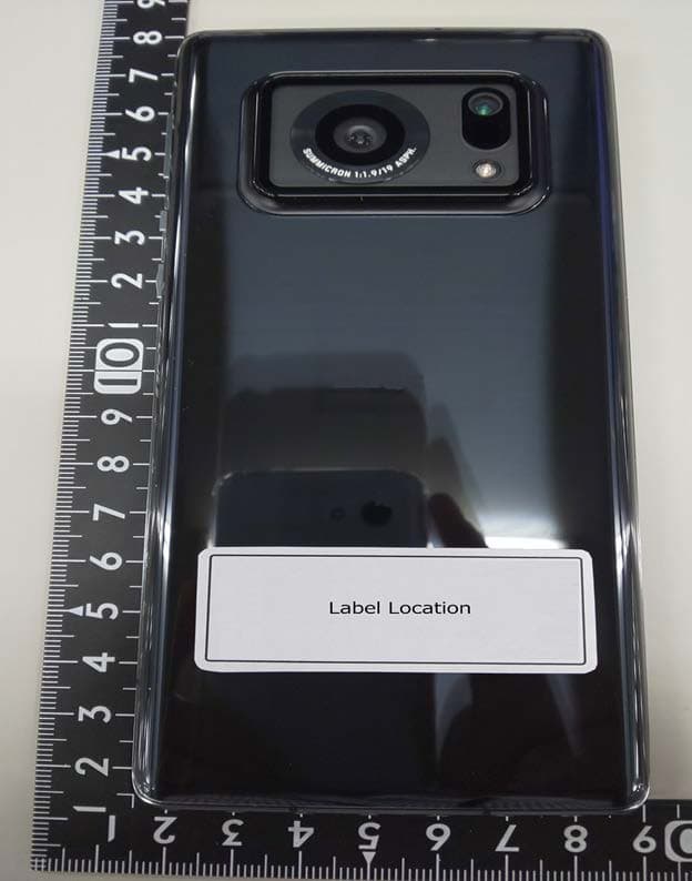
Click to zoom
Application Details
- Equipment Class
- NII - Unlicensed National Information Infrastructure TX
- Date of Grant
- May 10, 2021
- Application Purpose
- Original Equipment
- Date of Application
- May 07, 2021
- Equipment Note
- Mobile phone with Bluetooth, WiFi, GSM, WCDMA, LTE and NFC
- Frequency Range
- 5745.00000000 - 5825.00000000
- Company
- Sharp Corporation
- Country
- Japan
Documents & Files
Document Text
Text extracted from the exhibit documents filed with the FCC. Open a document above to read the original.
Users Manual
zThe screens and illustrations in this manual are shown as examples. The actual screens and illustrations may differ. zNote that “(*****)” is referred to as “handset” in this manual. zThis manual refers to microSD Card, microSDHC Card or microSDXC Card as “microSD Card” or “microSD”. zReproduction of this manual in part or in whole without prior permission is prohibited. zThe contents of this manual are subject to change without prior notice. Introduction Thank you for purchasing “(*****)”. Be sure to read this manual before and during use to ensure proper operation. 1 Contents/Precautions Basic package ***** (This drawing is not final) Quick Start guide (in Japanese only) •Purchase a specified charger (sold separately). The following items are not included in the package. •Earphone •USB Type-C cable •microSD memory card •AC adapter 7 Contents/Precautions Precautions (ALWAYS FOLLOW THESE DIRECTIONS) Before use, read these “Precautions” carefully and use your handset properly. These precautions contain information intended to prevent bodily injur y to the user and to surrounding people, as well as damage to property, and must be observed at all times. The following symbols indicate the different degrees of injury or damage that may occur if information provided is not observed and the handset is used improperly. Danger This symbol indicates that “death or serious bodily injury ( *1 ) may directly and immediately result from improper use”. Warning This symbol indicates that “death or serious bodily injury ( *1 ) may result from improper use”. Caution This symbol indicates that “minor injury ( *2 ) and/or property damage ( *3 ) may result from improper use”. *1 Serious bodily injury: This refers to loss of eyesight, bodily injury, burns (high- and low-temperature), electric shock, broken bones, injuries with residual aftereffects from poisoning, etc., and injuries requiring hospital admission for treatment or long-term hospital attendance as an outpatient. *2 Minor injury: This refers to bodily injury, burns (high- and low-temperature), electric shock, etc. that do not require hospital admission for treatment or long-term hospital attendance as an outpatient. *3 Property damage: This refers to extended damage to buildings, furniture, livestock, pets, etc. The following symbols indicate specific directions. Indicates a prohibited action. Indicates not to handle the device with wet hands. Indicates not to disassemble the device. Indicates that instructions specified are compulsory (must be followed). Indicates not to use the device near water or get it wet. Indicates that the power cord must be unplugged from the outlet. 8 Contents/Precautions “Precautions” is explained in the following sections. zHandling the handset, adapters, nano UIM card and TV antenna cable (general) ..............................P. 8 z Handling the handset ...............................P.10 z Handling adapters .................................P.14 z Handling nano UIM card ............................P.16 z Handling near electronic medical equipment .............P.16 z Material list ......................................P.17 z Handling the sample (SIM eject tool) ...................P.18 Handling the handset, adapters, nano UIM card and TV antenna cable (general) Danger Do not use, store or leave the equipment in locations subject to high temperatures or accumulation of heat (near a fire or heating unit, in a kotatsu or bedding, under direct sunlight, inside a vehicle on a hot day, etc.). May cause fires, burns, bodily injury, electric shock, etc. Do not place the equipment inside cooking appliances such as microwave ovens and induction cookers or high pressure vessels such as pressure cookers, or near them. May cause fires, burns, bodily injury, electric shock, etc. Do not sprinkle sand, soil or dirt on the equipment or put the equipment directly on it. Also, do not touch the equipment when sand etc. is adhering to your hand. May cause fires, burns, bodily injury, electric shock, etc. Refer to the following for details on waterproofness/ dustproofness. ☞ P. 26 “Waterproof/Dustproof” Do not charge the equipment while it is wet with liquids such as water (drinking water, sweat, seawater, pet urine, etc.). May cause fires, burns, bodily injury, electric shock, etc. Refer to the following for details on waterproofness. ☞ P. 26 “Waterproof/Dustproof” Do not press the equipment strongly or broken it. Especially when you put and carry it in the pocket, do not let it hit or caught in the object . May cause fires, burns, bodily injury, etc. because of catching fire, exploding, overheating or leaking of the internal battery. ※Take particular care with the followings z Sitting or squatting down while you are putting the equipment in your pocket of trousers or skirt z Letting the equipment caught in the door or vehicular door while you are putting the equipment in your pocket of outerwear z Stepping on the equipment while it is placing on the soft object such as the sof a or bedding, floor 9 Contents/Precautions Do not attempt to disassemble or modify the equipment. May cause fires, burns, bodily injury, electric shock, etc. Do not get the equipment wet with liquids such as water (drinking water, sweat, seawater, pet urine, etc.). May cause fires, burns, bodily injury, electric shock, etc. Refer to the following for details on waterproofness. ☞ P. 26 “Waterproof/Dustproof” Do not allow liquids such as water (drinking water, sweat, seawater, pet urine, etc.) to get inside the charger terminal or external connection jack. May cause fires, burns, bodily injury, electric shock, etc. Refer to the following for details on waterproofness. ☞ P. 26 “Waterproof/Dustproof” Use only optional parts specified by ●●● . May cause fires, burns, bodily injury, electric shock, etc. Warning Do not subject the equipment to strong force, impacts or vibration such as letting it fall, stepping on it or throwing it. May cause fires, burns, bodily …
Text truncated - open the document above for the full version.
External Photos
External Photos FCC ID:APYHRO00295 1/ 3 External Photos FCC ID:APYHRO00295 2/ 3 External Photos FCC ID:APYHRO00295 3/ 3
ID Label/Location Info
FCC ID Location FCC ID : APYHRO00295 ○e-label (on the display) ○Access to the information on the e-label Users are able to access the information in no more than three steps in the device Settings menu. STEP1: Click on "About phone" STEP2: Click on "Authentication" ○Instruction of e-label on the user manual * Users are provided specific instructions on how to access the information. FCC Notice (FCC ID Location) ○Labeling for Purchasing The FCC ID is printed on the package. 〇Note * The information is stored on the device, no special accessories or supplemental plug-ins (e.g., SIM/USIM card) are required to access the information. * Users are provided specific instructions on how to access the information. The user cannot modify the e-label information. FCC ID: APYHRO00295 Model Name Manufacturer
ID Label/Location Info
Packing information FCC ID:APYHRO00295
Internal Photos
Internal Photos FCC ID:APYHRO00295 1/ 17 Internal Photos FCC ID:APYHRO00295 2/ 17 Internal Photos FCC ID:APYHRO00295 3/ 17 Internal Photos FCC ID:APYHRO00295 4/ 17 Internal Photos FCC ID:APYHRO00295 5/ 17 Internal Photos FCC ID:APYHRO00295 6/ 17 Internal Photos FCC ID:APYHRO00295 7/ 17 Internal Photos FCC ID:APYHRO00295 8/ 17 Internal Photos FCC ID:APYHRO00295 9/ 17 Internal Photos FCC ID:APYHRO00295 10/ 17 Internal Photos FCC ID:APYHRO00295 11/ 17 Internal Photos FCC ID:APYHRO00295 12/ 17 Internal Photos FCC ID:APYHRO00295 13/ 17 Internal Photos FCC ID:APYHRO00295 14/ 17 Internal Photos FCC ID:APYHRO00295 15/ 17 【BB PCB】 Internal Photos FCC ID:APYHRO00295 16/ 17 【IP PCB】 Internal Photos FCC ID:APYHRO00295 17/ 17 【RF PCB】
RF Exposure Info
No.:SRTC2021-9004(F)-21010801(H) FCC ID: APYHRO00295 The State Radio_monitoring_centerTestingCenter (SRTC) Page number: 1 of 31 Tel:86-10-5799618 Fax:86-10-57996388 V3.0.0 ANNEX A – TEST PLOTS System check 750MHz Communication System: UID 0, CW (0) Frequency: 750 MHz; Duty cycle:1:1 Medium parameters used: f = 750 MHz; σ = 0.923 S/m; ε r = 41.352; ρ = 1000 kg/m 3 Phantom section: Flat Section DASY Configuration: Probe: EX3DV4 - SN3708; ConvF(9.63, 9.63, 9.63) @ 750MHz; Calibrated: 10/30/2020 Sensor-Surface: 1.4mm (Mechanical Surface Detection) Electronics: DAE4 Sn720; Calibrated: 9/30/2020 Phantom: Twin-SAM 1559; Type: QD 000 P40 CD; Serial: xxxx Measurement SW: DASY52, Version 52.10 (2); SEMCAD X Version 14.6.12 (7450) System Performance Check at Frequencies 750MHz/d=15mm, Pin=250 mW, dist=3.0mm (ES-Probe)/Area Scan (8x15x1): Measurement grid: dx=15mm, dy=15mm Maximum value of SAR (measured) = 2.16 W/kg System Performance Check at Frequencies 750MHz/d=15mm, Pin=250 mW, dist=3.0mm (ES-Probe)/Zoom Scan (7x7x7) (7x7x7)/Cube 0: Measurement grid: dx=5mm, dy=5mm, dz=5mm Reference Value = 41.00 V/m; Power Drift = 0.13 dB Peak SAR (extrapolated) = 3.26 W/kg SAR(1 g) = 2.11 W/kg; SAR(10 g) = 1.45 W/kg Maximum value of SAR (measured) = 2.49 W/kg No.:SRTC2021-9004(F)-21010801(H) FCC ID: APYHRO00295 The State Radio_monitoring_centerTestingCenter (SRTC) Page number: 2 of 31 Tel:86-10-5799618 Fax:86-10-57996388 V3.0.0 System check 835MHz Communication System: UID 0, CW (0); Frequency: 835 MHz Medium parameters used (interpolated): f = 835 MHz; σ = 0.911 S/m; ε r = 40.266 ρ = 1000 kg/m 3 Phantom section: Flat Section DASY5 Configuration: Probe: EX3DV4 - SN3708; ConvF(9.48, 9.48, 9.48) @ 835 MHz; Calibrated: 10/30/2020 Sensor-Surface: 1.4mm (Mechanical Surface Detection), Sensor-Surface: 1.4mm (Mechanical Surface Detection) Electronics: DAE4 Sn720; Calibrated: 9/30/2020 Phantom: Twin-SAM 1559; Type: QD 000 P40 CD; Serial: xxxx Measurement SW: DASY52, Version 52.10 (2); SEMCAD X Version 14.6.12 (7450) Configuration 835/835/Area Scan (8x15x1): Measurement grid: dx=15mm, dy=15mm Maximum value of SAR (measured) = 2.72 W/kg Configuration 835/835/Zoom Scan (7x7x7) (7x7x7)/Cube 0: Measurement grid: dx=5mm, dy=5mm, dz=5mm Reference Value = 51.67 V/m; Power Drift = 0.08 dB Peak SAR (extrapolated) = 3.58 W/kg SAR(1 g) = 2.31 W/kg; SAR(10 g) = 1.51 W/kg Maximum value of SAR (measured) = 2.75 W/kg No.:SRTC2021-9004(F)-21010801(H) FCC ID: APYHRO00295 The State Radio_monitoring_centerTestingCenter (SRTC) Page number: 3 of 31 Tel:86-10-5799618 Fax:86-10-57996388 V3.0.0 System check 1800MHz Communication System: UID 0, CW (0); Frequency: 1800 MHz; Duty cycle:1:1 Medium parameters used: f = 1800 MHz; σ = 1.418 S/m; ε r = 40.688; ρ = 1000 kg/m 3 Phantom section: Flat Section DASY5 Configuration: Probe: EX3DV4 - SN3708; ConvF(8.41, 8.41, 8.41) @ 1800 MHz; Calibrated: 10/30/2020 Sensor-Surface: 1.4mm (Mechanical Surface Detection) Electronics: DAE4 Sn720; Calibrated: 9/30/2020 Phantom: Twin-SAM 1559; Type: QD 000 P40 CD; Serial: xxxx Measurement SW: DASY52, Version 52.10 (2); SEMCAD X Version 14.6.12 (7450) Configuration 1800/1800/Area Scan (7x10x1): Measurement grid: dx=15mm, dy=15mm Maximum value of SAR (measured) = 8.31 W/kg Configuration 1800/1800/Zoom Scan (7x7x7) (7x7x7)/Cube 0: Measurement grid: dx=5mm, dy=5mm, dz=5mm Reference Value = 76.60 V/m; Power Drift = 0.01 dB Peak SAR (extrapolated) = 17.5 W/kg SAR(1 g) = 9.49 W/kg; SAR(10 g) = 4.97 W/kg Maximum value of SAR (measured) = 12.1 W/kg No.:SRTC2021-9004(F)-21010801(H) FCC ID: APYHRO00295 The State Radio_monitoring_centerTestingCenter (SRTC) Page number: 4 of 31 Tel:86-10-5799618 Fax:86-10-57996388 V3.0.0 System check 2000MHz Communication System: UID 0, CW (0); Frequency: 2000 MHz; Duty cycle:1:1 Medium parameters used: f = 2000 MHz; σ = 1.427 S/m; ε r = 39.844; ρ = 1000 kg/m 3 Phantom section: Flat Section DASY5 Configuration: Probe: EX3DV4 - SN3708; ConvF(8.09, 8.09, 8.09) @ 2000 MHz; Calibrated: 10/30/2020 Sensor-Surface: 1.4mm (Mechanical Surface Detection) Electronics: DAE4 Sn720; Calibrated: 9/30/2020 Phantom: Twin-SAM 1559; Type: QD 000 P40 CD; Serial: xxxx Measurement SW: DASY52, Version 52.10 (2); SEMCAD X Version 14.6.12 (7450) Configuration 2000/2000/Area Scan (7x10x1): Measurement grid: dx=10mm, dy=10mm Maximum value of SAR (measured) = 8.40 W/kg Configuration 2000/2000/Zoom Scan (7x7x7) (7x7x7)/Cube 0: Measurement grid: dx=5mm, dy=5mm, dz=5mm Reference Value = 76.22 V/m; Power Drift = 0.07 dB Peak SAR (extrapolated) = 18.7 W/kg SAR(1 g) = 9.76 W/kg; SAR(10 g) = 4.96 W/kg Maximum value of SAR (measured) = 12.9 W/kg No.:SRTC2021-9004(F)-21010801(H) FCC ID: APYHRO00295 The State Radio_monitoring_centerTestingCenter (SRTC) Page number: 5 of 31 Tel:86-10-5799618 Fax:86-10-57996388 V3.0.0 System check 2450MHz Communication System: UID 0, CW (0); Frequency: 2450 MHz; Duty cycle:1:1 Medium parameters used: f = 2450 MHz; σ = 1.866 S/m; ε r = 38.343; ρ = 1000 kg/m 3 Phantom section: Flat Section DASY5 Configuration: Probe: EX3DV4 - SN3708; ConvF(7.5, 7.5, 7.5) @ 2450 MHz; Calibrated: 10/30/2020 Sensor-Surface: 1.4mm (Mechanical Surface Detection) Electronics: DAE4 Sn720; Calibrated: 9/30/2020 Phantom: Twin-SAM 1559; Type: QD 000 P40 CD; Serial: xxxx Measurement SW: DASY52, Version 52.10 (2); SEMCAD X Version 14.6.12 (7450) System Performance Check at Frequencies 2450 MHz/2450/Area Scan (8x11x1): Measurement grid: dx=12mm, dy=12mm Maximum value of SAR (measured) = 21.2 W/kg System Performance Check at Frequencies 2450 MHz/2450/Zoom Scan (7x7x7) (7x7x7)/Cube 0: Measurement grid: dx=5mm, dy=5mm, dz=5mm Reference Value = 108.3 V/m; Power Drift = 0.19 dB Peak SAR (extrapolated) = 28.2 W/kg SAR(1 g) = 12.5 W/kg; SAR(10 g) = 6.14 W/kg Maximum value of SAR (measured) = 22.6 W/kg No.:SRTC2021-9004(F)-21010801(H) FCC ID: APYHRO00295 The State Radio_monitoring_centerTestingCenter (SRTC) Page number: 6 of 31 Tel:86-10-57…
Text truncated - open the document above for the full version.
RF Exposure Info
TEST REPORT FOR SAR TESTING Report No:SRTC2021-9004(F)-21010801(H) Product Name: Mobile phone Applicant: Sharp Corporation Manufacturer: Sharp Corporation Specification: Part 2.1093 IEEE Std 1528 KDB Procedures FCC ID: APYHRO00295 The State Radio_monitoring_center Testing Center (SRTC) 15th Building, No.30 Shixing Street, Shijingshan District, Beijing, P.R. China Tel: 86-10-57996183 Fax: 86-10-57996388 No.:SRTC2021-9004(F)-21010801(H) FCC ID: APYHRO00295 The State Radio_monitoring_center Testing Center (SRTC)Page number: 1 of 194 Tel: 86-10-57996183 Fax: 86-10-57996388V3.0.0 Contents 1. GENERAL INFORMATION ............................................................................................... 2 1.1 NOTES OF THE TEST REPORT ............................................................................................................................ 2 1.2 INFORMATION ABOUT THE TESTING LABORATORY ............................................................................................... 2 1.3 APPLICANT’S DETAILS ....................................................................................................................................... 2 1.4 MANUFACTURER’S DETAILS ............................................................................................................................... 2 1.5 TEST ENVIRONMENT ......................................................................................................................................... 3 2. DESCRIPTION OF THE DEVICE UNDER TEST .............................................................. 4 2.1 FINAL EQUIPMENT BUILD STATUS ..................................................................................................................... 4 2.2 SUPPORT EQUIPMENT ...................................................................................................................................... 5 2.3 OTHER EQUIPMENT INFORMATION ..................................................................................................................... 5 3. REFERENCE SPECIFICATION ........................................................................................ 6 4. TEST CONDITIONS .......................................................................................................... 7 4.1 PICTURE TO DEMONSTRATE THE REQUIRED LIQUID DEPTH .................................................................................. 7 4.2 TEST SIGNAL, FREQUENCIES AND OUTPUT POWER ............................................................................................ 7 4.3 SAR MEASUREMENT SET-UP ............................................................................................................................ 7 4.4 PHANTOMS ...................................................................................................................................................... 8 4.5 TISSUE SIMULANTS .......................................................................................................................................... 8 4.6 DESCRIPTION OF THE TEST PROCEDURE .............................................................................................. 9 5 RESULT SUMMARY ........................................................................................................ 12 6 TEST RESULT ................................................................................................................. 15 6.1 MEASUREMENT RESULT .................................................................................................................................. 15 6.2 STANDALONE SAR TEST EXCLUSION CONSIDERATIONS ................................................................................. 136 6.3 RF EXPOSURE CONDITIONS .......................................................................................................................... 138 6.4 SYSTEM CHECKING ...................................................................................................................................... 144 6.5 SAR TEST RESULT ................................................................................................................................... 145 6.6 SAR MEASUREMENT VARIABILITY ................................................................................................................. 186 6.7 SIMULTANEOUS TRANSMISSION SAR ANALYSIS ............................................................................................. 186 7 MEASUREMENT UNCERTAINTY ................................................................................. 187 8 TEST EQUIPMENTS ...................................................................................................... 189 ANNEX A – TEST PLOTS ................................................................................................. 194 No.:SRTC2021-9004(F)-21010801(H) FCC ID: APYHRO00295 The State Radio_monitoring_center Testing Center (SRTC)Page number: 2 of 194 Tel: 86-10-57996183 Fax: 86-10-57996388V3.0.0 1. GENERAL INFORMATION 1.1 Notes of the test report The test report may only be reproduced or published in full. Reproduction or publication of extracts from the report requires the prior written permission of The State Radio_monitoring_center Testing Center (SRTC). The test results relate only to individual items of the samples which have been tested. The certification and accreditation identifiers used in this report shall not be applicable to the tested or calibrated samples thereof. The manufacturer shall not mark the tested samples or items (or a separate part of the item) with the identifiers of certification and accreditation to mislead relevant parties about the tested samples or items. 1.2 Information about the testing laboratory Company: The State Radio_monitoring_center Testing Center (SRTC) Address: 15th Building, No.30 Shixing Street, Shijingshan District, Beijing P.R. China City: Beijing Country or Region: P.R. China Contacted…
Text truncated - open the document above for the full version.
RF Exposure Info
No.:SRTC2021-9004(F)-21010801(H) FCC ID: APYHRO00295 The State Radio_monitoring_centerTestingCenter (SRTC) Page number: 1 of 31 Tel:86-10-5799618 Fax:86-10-57996388 V3.0.0 ANNEX A – TEST PLOTS System check 750MHz Communication System: UID 0, CW (0) Frequency: 750 MHz; Duty cycle:1:1 Medium parameters used: f = 750 MHz; σ = 0.923 S/m; ε r = 41.352; ρ = 1000 kg/m 3 Phantom section: Flat Section DASY Configuration: Probe: EX3DV4 - SN3708; ConvF(9.63, 9.63, 9.63) @ 750MHz; Calibrated: 10/30/2020 Sensor-Surface: 1.4mm (Mechanical Surface Detection) Electronics: DAE4 Sn720; Calibrated: 9/30/2020 Phantom: Twin-SAM 1559; Type: QD 000 P40 CD; Serial: xxxx Measurement SW: DASY52, Version 52.10 (2); SEMCAD X Version 14.6.12 (7450) System Performance Check at Frequencies 750MHz/d=15mm, Pin=250 mW, dist=3.0mm (ES-Probe)/Area Scan (8x15x1): Measurement grid: dx=15mm, dy=15mm Maximum value of SAR (measured) = 2.16 W/kg System Performance Check at Frequencies 750MHz/d=15mm, Pin=250 mW, dist=3.0mm (ES-Probe)/Zoom Scan (7x7x7) (7x7x7)/Cube 0: Measurement grid: dx=5mm, dy=5mm, dz=5mm Reference Value = 41.00 V/m; Power Drift = 0.13 dB Peak SAR (extrapolated) = 3.26 W/kg SAR(1 g) = 2.11 W/kg; SAR(10 g) = 1.45 W/kg Maximum value of SAR (measured) = 2.49 W/kg No.:SRTC2021-9004(F)-21010801(H) FCC ID: APYHRO00295 The State Radio_monitoring_centerTestingCenter (SRTC) Page number: 2 of 31 Tel:86-10-5799618 Fax:86-10-57996388 V3.0.0 System check 835MHz Communication System: UID 0, CW (0); Frequency: 835 MHz Medium parameters used (interpolated): f = 835 MHz; σ = 0.911 S/m; ε r = 40.266 ρ = 1000 kg/m 3 Phantom section: Flat Section DASY5 Configuration: Probe: EX3DV4 - SN3708; ConvF(9.48, 9.48, 9.48) @ 835 MHz; Calibrated: 10/30/2020 Sensor-Surface: 1.4mm (Mechanical Surface Detection), Sensor-Surface: 1.4mm (Mechanical Surface Detection) Electronics: DAE4 Sn720; Calibrated: 9/30/2020 Phantom: Twin-SAM 1559; Type: QD 000 P40 CD; Serial: xxxx Measurement SW: DASY52, Version 52.10 (2); SEMCAD X Version 14.6.12 (7450) Configuration 835/835/Area Scan (8x15x1): Measurement grid: dx=15mm, dy=15mm Maximum value of SAR (measured) = 2.72 W/kg Configuration 835/835/Zoom Scan (7x7x7) (7x7x7)/Cube 0: Measurement grid: dx=5mm, dy=5mm, dz=5mm Reference Value = 51.67 V/m; Power Drift = 0.08 dB Peak SAR (extrapolated) = 3.58 W/kg SAR(1 g) = 2.31 W/kg; SAR(10 g) = 1.51 W/kg Maximum value of SAR (measured) = 2.75 W/kg No.:SRTC2021-9004(F)-21010801(H) FCC ID: APYHRO00295 The State Radio_monitoring_centerTestingCenter (SRTC) Page number: 3 of 31 Tel:86-10-5799618 Fax:86-10-57996388 V3.0.0 System check 1800MHz Communication System: UID 0, CW (0); Frequency: 1800 MHz; Duty cycle:1:1 Medium parameters used: f = 1800 MHz; σ = 1.418 S/m; ε r = 40.688; ρ = 1000 kg/m 3 Phantom section: Flat Section DASY5 Configuration: Probe: EX3DV4 - SN3708; ConvF(8.41, 8.41, 8.41) @ 1800 MHz; Calibrated: 10/30/2020 Sensor-Surface: 1.4mm (Mechanical Surface Detection) Electronics: DAE4 Sn720; Calibrated: 9/30/2020 Phantom: Twin-SAM 1559; Type: QD 000 P40 CD; Serial: xxxx Measurement SW: DASY52, Version 52.10 (2); SEMCAD X Version 14.6.12 (7450) Configuration 1800/1800/Area Scan (7x10x1): Measurement grid: dx=15mm, dy=15mm Maximum value of SAR (measured) = 8.31 W/kg Configuration 1800/1800/Zoom Scan (7x7x7) (7x7x7)/Cube 0: Measurement grid: dx=5mm, dy=5mm, dz=5mm Reference Value = 76.60 V/m; Power Drift = 0.01 dB Peak SAR (extrapolated) = 17.5 W/kg SAR(1 g) = 9.49 W/kg; SAR(10 g) = 4.97 W/kg Maximum value of SAR (measured) = 12.1 W/kg No.:SRTC2021-9004(F)-21010801(H) FCC ID: APYHRO00295 The State Radio_monitoring_centerTestingCenter (SRTC) Page number: 4 of 31 Tel:86-10-5799618 Fax:86-10-57996388 V3.0.0 System check 2000MHz Communication System: UID 0, CW (0); Frequency: 2000 MHz; Duty cycle:1:1 Medium parameters used: f = 2000 MHz; σ = 1.427 S/m; ε r = 39.844; ρ = 1000 kg/m 3 Phantom section: Flat Section DASY5 Configuration: Probe: EX3DV4 - SN3708; ConvF(8.09, 8.09, 8.09) @ 2000 MHz; Calibrated: 10/30/2020 Sensor-Surface: 1.4mm (Mechanical Surface Detection) Electronics: DAE4 Sn720; Calibrated: 9/30/2020 Phantom: Twin-SAM 1559; Type: QD 000 P40 CD; Serial: xxxx Measurement SW: DASY52, Version 52.10 (2); SEMCAD X Version 14.6.12 (7450) Configuration 2000/2000/Area Scan (7x10x1): Measurement grid: dx=10mm, dy=10mm Maximum value of SAR (measured) = 8.40 W/kg Configuration 2000/2000/Zoom Scan (7x7x7) (7x7x7)/Cube 0: Measurement grid: dx=5mm, dy=5mm, dz=5mm Reference Value = 76.22 V/m; Power Drift = 0.07 dB Peak SAR (extrapolated) = 18.7 W/kg SAR(1 g) = 9.76 W/kg; SAR(10 g) = 4.96 W/kg Maximum value of SAR (measured) = 12.9 W/kg No.:SRTC2021-9004(F)-21010801(H) FCC ID: APYHRO00295 The State Radio_monitoring_centerTestingCenter (SRTC) Page number: 5 of 31 Tel:86-10-5799618 Fax:86-10-57996388 V3.0.0 System check 2450MHz Communication System: UID 0, CW (0); Frequency: 2450 MHz; Duty cycle:1:1 Medium parameters used: f = 2450 MHz; σ = 1.866 S/m; ε r = 38.343; ρ = 1000 kg/m 3 Phantom section: Flat Section DASY5 Configuration: Probe: EX3DV4 - SN3708; ConvF(7.5, 7.5, 7.5) @ 2450 MHz; Calibrated: 10/30/2020 Sensor-Surface: 1.4mm (Mechanical Surface Detection) Electronics: DAE4 Sn720; Calibrated: 9/30/2020 Phantom: Twin-SAM 1559; Type: QD 000 P40 CD; Serial: xxxx Measurement SW: DASY52, Version 52.10 (2); SEMCAD X Version 14.6.12 (7450) System Performance Check at Frequencies 2450 MHz/2450/Area Scan (8x11x1): Measurement grid: dx=12mm, dy=12mm Maximum value of SAR (measured) = 21.2 W/kg System Performance Check at Frequencies 2450 MHz/2450/Zoom Scan (7x7x7) (7x7x7)/Cube 0: Measurement grid: dx=5mm, dy=5mm, dz=5mm Reference Value = 108.3 V/m; Power Drift = 0.19 dB Peak SAR (extrapolated) = 28.2 W/kg SAR(1 g) = 12.5 W/kg; SAR(10 g) = 6.14 W/kg Maximum value of SAR (measured) = 22.6 W/kg No.:SRTC2021-9004(F)-21010801(H) FCC ID: APYHRO00295 The State Radio_monitoring_centerTestingCenter (SRTC) Page number: 6 of 31 Tel:86-10-57…
Text truncated - open the document above for the full version.
RF Exposure Info
TEST REPORT FOR SAR TESTING Report No:SRTC2021-9004(F)-21010801(H) Product Name: Mobile phone Applicant: Sharp Corporation Manufacturer: Sharp Corporation Specification: Part 2.1093 IEEE Std 1528 KDB Procedures FCC ID: APYHRO00295 The State Radio_monitoring_center Testing Center (SRTC) 15th Building, No.30 Shixing Street, Shijingshan District, Beijing, P.R. China Tel: 86-10-57996183 Fax: 86-10-57996388 No.:SRTC2021-9004(F)-21010801(H) FCC ID: APYHRO00295 The State Radio_monitoring_center Testing Center (SRTC)Page number: 1 of 194 Tel: 86-10-57996183 Fax: 86-10-57996388V3.0.0 Contents 1. GENERAL INFORMATION ............................................................................................... 2 1.1 NOTES OF THE TEST REPORT ............................................................................................................................ 2 1.2 INFORMATION ABOUT THE TESTING LABORATORY ............................................................................................... 2 1.3 APPLICANT’S DETAILS ....................................................................................................................................... 2 1.4 MANUFACTURER’S DETAILS ............................................................................................................................... 2 1.5 TEST ENVIRONMENT ......................................................................................................................................... 3 2. DESCRIPTION OF THE DEVICE UNDER TEST .............................................................. 4 2.1 FINAL EQUIPMENT BUILD STATUS ..................................................................................................................... 4 2.2 SUPPORT EQUIPMENT ...................................................................................................................................... 5 2.3 OTHER EQUIPMENT INFORMATION ..................................................................................................................... 5 3. REFERENCE SPECIFICATION ........................................................................................ 6 4. TEST CONDITIONS .......................................................................................................... 7 4.1 PICTURE TO DEMONSTRATE THE REQUIRED LIQUID DEPTH .................................................................................. 7 4.2 TEST SIGNAL, FREQUENCIES AND OUTPUT POWER ............................................................................................ 7 4.3 SAR MEASUREMENT SET-UP ............................................................................................................................ 7 4.4 PHANTOMS ...................................................................................................................................................... 8 4.5 TISSUE SIMULANTS .......................................................................................................................................... 8 4.6 DESCRIPTION OF THE TEST PROCEDURE .............................................................................................. 9 5 RESULT SUMMARY ........................................................................................................ 12 6 TEST RESULT ................................................................................................................. 15 6.1 MEASUREMENT RESULT .................................................................................................................................. 15 6.2 STANDALONE SAR TEST EXCLUSION CONSIDERATIONS ................................................................................. 136 6.3 RF EXPOSURE CONDITIONS .......................................................................................................................... 138 6.4 SYSTEM CHECKING ...................................................................................................................................... 144 6.5 SAR TEST RESULT ................................................................................................................................... 145 6.6 SAR MEASUREMENT VARIABILITY ........................................................…
Text truncated - open the document above for the full version.
Contact Information
Applicant
Taihei Ohtsuka(Division Manager, ESG & Q promotion div.)
Test Firm
The State Radio_monitoring_center Testing CenterSun Yang
[email protected]+86-10-57996131
Technical Specifications
| # | Rule Parts | Frequency Range | Power Output |
|---|---|---|---|
| 4 | 15E | 5.75 GHz - 5.83 GHz | 27.00 mW |
Other Applications from Sharp Corporation
APYHRO00343
Aug 17, 2026Smartphone
Equipment Class
DTS - Digital Transmission SystemAPYHRO00342
Jul 29, 2026Smart phone
Equipment Class
DXX - Part 15 Low Power Communication Device TransmitterAPYHRO00341
May 28, 2026Smart phone
Equipment Class
DTS - Digital Transmission SystemAPYHRO00340
Dec 01, 2025BT remote control
Equipment Class
DTS - Digital Transmission SystemAPYHRO00339
Sep 17, 2025Smart phone
Equipment Class
NII - Unlicensed National Information Infrastructure TX