APYMXEB13Wireless LAN USB Adaptor
Sharp Corporation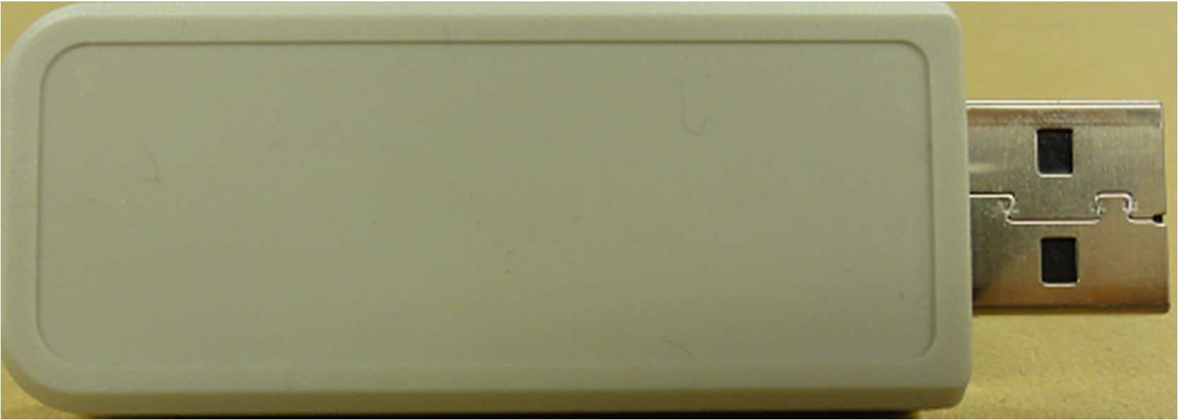
Click to zoom
Application Details
- Equipment Class
- DTS - Digital Transmission System
- Date of Grant
- May 23, 2012
- Application Purpose
- Original Equipment
- Date of Application
- May 23, 2012
- Equipment Note
- Wireless LAN USB Adaptor
- Frequency Range
- 2412.00000000 - 2462.00000000
- Company
- Sharp Corporation
- Country
- Japan
Documents & Files
Document Text
Text extracted from the exhibit documents filed with the FCC. Open a document above to read the original.
Users Manual
MX-EB13 WIRELESS LAN USB ADAPTER DATA SHEET PART NAMES AND FUNCTIONS ADAPTOR SPECIFICATIONS Model MX-EB13 Type Wireless LAN USB Adapter Standards IEEE 802.11n/g/b Wireless Signal Rates With Automatic Fallback 11n: 6.5/13/19.5/26/39/52/58.5/65Mbps (20MHz BW, Long Guard interval) 7.2/14.4/21.7/28.9/43.3/57.8/65/72.2Mbps (20MHz BW, Short Guard interval) 13.5/27/40.5/54/81/108/121.5/135Mbps (40MHz BW, Long Guard interval) 15/30/45/60/90/120/135/150Mbps (40MHz BW, Short Guard interval) 11g: 6/9/12/18/24/36/48/54Mbps 11b: 1/2/5.5/11Mbps Wireless Frequency Range 2.400GHz to 2.483.5GHz Protocol TCP/IP Channel Number Ch1-11 Receiver sensitivity 54M: -74dBm(typ) -65dBm(max) 11M: -90dBm(typ) -76dBm(max) 6M: -91dBm(typ) -82dBm(max) 1M: -95dBm(typ) -80dBm(max) MCS 0(20MHz):-89dBm(typ) -80dBm(max) MCS 7(20MHz):-70dBm(typ) -63dBm(max) MCS 0(40MHz):-87dBm(typ) -77dBm(max) MCS 7(40MHz):-68dBm(typ) -59dBm(max) Spread Spectrum Method Orthogonal Frequency Division Multiplexing (OFDM) (64QAM,16QAM,DQPSK,DBPSK) Direct Sequence Spread Spectrum(DSSS) (CCK,DQPSK,DBPSK) Power 5V Bus powers Wireless Transmit Power Max. 19dBm Security WPA2-PSK(AES),WPA2-EAP(AES),WPA-PSK(TKIP/AES) WPA-EAP(TKIP/AES),WEP(128/64bit) Bus Interface USB 2.0 Antenna Integrated internal antenna Emissions CE,FCC,IC Package Content Wireless LAN Adapter , Manual Dimensions (W x D x H) 22.5x64x9.6mm Weight Approx.11g LED indicator 1 When this indicator is blinking, the adaptor is communicating. When this indicator is blinking slowly, the adaptor is not communicating or no connection is established. LED indicator 2 When this indicator is lit, a connection is established. When this indicator is blinking fast, the wireless setting is enabled or no connection is established. When this indicator is blinking slowly, the wireless setting is disabled. LED1 LED2 Wireless LAN USB Adapter For Users in the USA For Users in Canada This device complies with Part15 of FCC Rules . Ope ration is subject to the following two conditions: (1) This device may not cause harmful interference ,and (2) this device must accept any interference receiv ed, including interference that may cause undesired operation. This Class A digital apparatus complies with Canadi an ICES-003. Cet appareil numérique de la classe A est conforme à la norme NMB-003 du Canada. NOTE: This equipment has been tested and found to comply with the limits for a Class A digital device, pursu ant to Part 15 of the FCC Rules. These limits are designed to provide reasonable protection against harmful interference when the equipment is operated in a co mmercial environment. This equipment generates, use s, and can radiate radio frequency energy and, if not inst alled and used in accordance with the instruction m anual, may cause harmful interference to radio communications. Operation of this equipment in a residential area is likely to cause harmful interference in which case the user w ill be required to correct the interference at his own expense. WARNING: FCC Regulations state that any unauthorized changes or modifications to this equipment not expressly a pproved by the manufacturer could void the user's authority to operate this equipment. This transmitter must not be co-located or operated in conjunction with any other antenna or transmitt er. This equipment complies with IC radiation exposure limits set forth for an uncontrolled environment an d meets RSS-102 of the IC radio frequency (RF) Exposure rul es. This equipment should be installed and operated keeping the radiator at least 20cm or more away fro m person’s body(excluding extremities: hands ,wrist s ,feet and ankles). This equipment complies with FCC radiation exposure limits set forth for an uncontrolled environment a nd meets the FCC radio frequency (RF) Exposure Guidelines in Supplement C to OET65 . This equipment should be installed and operated keeping the radiator at leas t 20cm or more away from person’s body (excluding extremities: hands ,wrists ,feet and ankles). This device complies with industry Canada licence - exempt RSS standard(s). Operation is subject to the following two conditions: (1) this device may not cause interference ,and (2) this device must accept any interference, inclu ding interference that may cause undesired operatio n of this device. Le présent appareil est conforme aux CNR d'Industri e Canada applicables aux appareils radio exempts de licence. L'exploitation est autorisée aux deux cond itions suivantes : (1) l'appareil ne doit pas produire de brouillage, et (2) l'utilisateur de l'appareil doit accepter tout brouillage radioélectrique subi, même si le brouill age est susceptible d'en compromettre le fonctionnement. Cet équipement est conforme aux limites d’expositio n aux rayonnements énoncées pour un environnement n on contrôlé et respecte les règles d’exposition aux fr équences radioélectriques (RF) CNR-102 de l’IC. Cet équipement doit être installé et utilisé en gar dant une distance de 20 cm ou plus entre le disposi tif rayonnant et le corps (à l’exception des extrémités : mains, poignets, pieds et chevilles). MX - EB13 WIRELESS LAN USB ADAPTER SAFETY G UIDE Notice for Users in Europe / Hinweis für Benutzer i n Europa / Avis pour nos utilisateurs en Europe / Opmerking voor gebruikers in Europa / A vviso per gli utenti europei / Aviso para usuarios de Europa / Bemærkning til brugere i Europa / Huomautus Euroopassa oleville käyttäjille / Bemerkning til brukere i Eur opa / Anvisningar för användare i Europa Hereby, SHARP Electronics (Europe) GmbH declares that th is Wireless LAN USB Adapter MX-EB13 is in compliance with the essential requirements and other relevant provisions of Directive 1999/5/EC. Par la présente, SHARP Electronics (Europe) GmbH déclare que l’appareil Wireless LAN USB Adapter MX-EB13 est conforme aux exigences essentielles et aux autres d ispositions pertinentes de la directive 1999/5/CE. Hiermit erklärt SHARP Electronics (Europe) GmbH, dass si ch das Gerät Wireless LAN USB Adapter MX-E…
Text truncated - open the document above for the full version.
External Photos
SHARP CORPORATION Model: MX-EB13 FCC ID:APYMXEB13 IC Number:548B-MXEB13 External Photo
ID Label/Location Info
MADE IN JAPAN SHARP CORPORATION FCC ID:APYMXEB13 IC:548B-MXEB13 MAC MX-EB13 WIRELESS LAN USB ADAPTER LOT No. MADE IN JAPAN SHARP CORPORATION FCC ID:APYMXEB13 IC:548B-MXEB13 MAC MX-EB13 WIRELESS LAN USB ADAPTER LOT No. MADE IN JAPAN SHARP CORPORATION FCC ID:APYMXEB13 IC:548B-MXEB13 MAC MX-EB13 WIRELESS LAN USB ADAPTER LOT No.
Internal Photos
SHARP CORPORATION Model: MX-EB13 FCC ID:APYMXEB13 IC Number:548B-MXEB13 Internal Photo
RF Exposure Info
UL Japan, Inc. Shonan EMC Lab. 1-22-3 Megumigaoka, Hiratsuka-shi, Kanagawa-ken, 259-1220 JAPAN Telephone : +81 463 50 6400 Facsimile : +81 463 50 6401 Applica nt: S harp Corporation T ype of Equipment : Wireless LAN USB Adapter M odel No. : M X-EB13 FCC ID: APYM XEB13 Sharp C orporation declares that M odel : W ireless LAN USB Adapter complies with FCC radiation exposure requirement specified in the FCC Rules 2.1091. The “M X-EB13“ has 175.79 mW of conducted Peak O utput power and 197.24 mW of EIRP. This equipment is considered as a mobile device so that SAR testing is excluded. The Following calculation is the reference data for 20cm distance. RF Exposure Calculations: The following information provides the minimum separation distance for the highest gain antenna provided with the “M X-EB13“ as calculated from FCC OET Bulletin 65 Appendix A, Table (B) Limits for General Population / Uncontrolled Exposure. This calculation is based on the highest EIRP possible from the system, considering maximum power and antenna gain, and considering a 1.0mW/cm^2 uncontrolled exposure limit. The Friis formula used was: S = (P * G) / (4* π * r 2 ) Where P = 175.79 mW (M aximum peak output power) G = 1.12 Numerical Antenna gain; equal 0.50 dBi r =20.0 cm For: M X-EB13S = 0.03924mW/cm 2 No. : 31AE0257-SH-03-A RF Ex posure / SAR Statement
Test Report
Test report No. : 31AE0257-SH-03-A Page : 2 of 70 Issued date : May 7, 2012 FCC ID : APYMXEB13 UL Japan, Inc. Shonan EMC Lab. 1-22-3 Megumigaoka, Hiratsuka-shi, Kanagawa-ken, 259-1220 JAPAN Telephone : +81 463 50 6400 Facsimile : +81 463 50 6401 REVISION HISTORY Original Test Report No.: 31AE0257-SH-03-A Revision Test report No. Date Page revised Contents - (Original) 31AE0257-SH-03-A May 7, 2012 - - Test report No. : 31AE0257-SH-03-A Page : 3 of 70 Issued date : May 7, 2012 FCC ID : APYMXEB13 UL Japan, Inc. Shonan EMC Lab. 1-22-3 Megumigaoka, Hiratsuka-shi, Kanagawa-ken, 259-1220 JAPAN Telephone : +81 463 50 6400 Facsimile : +81 463 50 6401 Contents Page SECTION 1: Customer information ..................................................................................... 4 SECTION 2: Equipment under test (E.U.T.) ....................................................................... 4 SECTION 3: Test specification, procedures & results ......................................................... 5 SECTION 4: Operation of E.U.T. during testing ................................................................. 8 SECTION 5: Conducted emission ....................................................................................... 10 SECTION 6: 6dB bandwidth & Occupied bandwidth (99%) ........................................... 10 SECTION 7: Maximum peak output power ....................................................................... 11 SECTION 8: Spurious emission (Antenna port conducted) .............................................. 11 SECTION 9: Radiated emission .......................................................................................... 12 SECTION 10: Peak Power density ...................................................................................... 13 Contents of APPENDIXES ................................................................................................... 14 APPENDIX 1: Test data ...................................................................................................... 15 APPENDIX 2: Test instruments .......................................................................................... 67 APPENDIX 3: Photographs of test setup ............................................................................ 68 Test report No. : 31AE0257-SH-03-A Page : 4 of 70 Issued date : May 7, 2012 FCC ID : APYMXEB13 UL Japan, Inc. Shonan EMC Lab. 1-22-3 Megumigaoka, Hiratsuka-shi, Kanagawa-ken, 259-1220 JAPAN Telephone : +81 463 50 6400 Facsimile : +81 463 50 6401 SECTION 1: Customer information Company Name : Sharp Corporation Address : 492 Minosho-cho, Yamatokoriyama-shi, Nara 639-1186, Japan Telephone Number : +81-743-55-4075 Facsimile Number : +81-743-55-5843 Contact Person : Yasuji Yamauchi SECTION 2: Equipment under test (E.U.T.) 2.1 Identification of E.U.T. Type of Equipment : Wireless LAN USB Adapter Model No. : MX-EB13 Serial No. : Refer to 4.2 in this report. Rating : DC5V Receipt Date of Sample : March 26, 2012 Country of Mass-production : Japan Condition of EUT : Production model Modification of EUT : No modification by the test lab. 2.2 Product description Model: MX-EB13 (referred to as the EUT in this report) is a Wireless LAN USB Adapter. Clock frequency(ies) in the system : Oscillator: 40MHz, VCO: 3.216 to 3.296GHz Radio specification Equipment type : Transceiver Frequency of operation : 2412-2462MHz Bandwidth & channel spacing : Bandwidth: 20MHz (IEEE 802.11b, 11g, 11n-HT20) / 40MHz (IEEE 802.11n-HT40) Channel spacing: 5MHz Type of modulation : DSSS: CCK,DQPSK, DBPSK OFDM: 64QAM, 16QAM, QPSK, BPSK Antenna type : Monopole pattern Antenna connector type : None Antenna gain with cable loss : +0.5 dBi ITU code : D1D, G1D Operation temperature range : -10 to +60 deg.C. FCC 15.31 (e) The adapter provides the Wireless transmitter with stable power supply (DC3.3V), therefore, the equipment complies with the requirement. FCC 15.203 The antenna is not removable from the EUT. Therefore, the equipment complies with the antenna requirement. Test report No. : 31AE0257-SH-03-A Page : 5 of 70 Issued date : May 7, 2012 FCC ID : APYMXEB13 UL Japan, Inc. Shonan EMC Lab. 1-22-3 Megumigaoka, Hiratsuka-shi, Kanagawa-ken, 259-1220 JAPAN Telephone : +81 463 50 6400 Facsimile : +81 463 50 6401 SECTION 3: Test specification, procedures & results 3.1 Test specification Test specification : FCC Part 15 Subpart C: 2012, final revised on March 30, 2012 and effective April 30, 2012 Title : FCC 47CFR Part15 Radio Frequency Device Subpart C Intentional Radiators Section 15.207 Conducted limits Section 15.209 Radiated emission limits, general requirements Section 15.247 Operation within the bands 902-928MHz, 2400-2483.5MHz, and 5725-5850MHz *The revision on March 30, 2012 does not affect the test specification applied to the EUT. The EUT complies with FCC Part 15 Subpart B. Refer to the test report 31AE0257-SH-03-C. 3.2 Procedures & Results Item Test Procedure Specification RemarksDeviationWorst Margin Results Conducted emission ANSI C63.4:2009 7. AC powerline conducted emission measurements FCC 15.207 - N/A 12.1dB Freq.: 0.22390MHz Detector: Quasi-Peak Phase: L1 Mode: Tx 2437MHz, IEEE 802.11g Complied 6dB bandwidth ANSI C63.4:2009 13. Measurement of intentional radiators FCC 15.247 (a)(2) & 15.209 ConductedN/A * See data Complied Maximum peak output power ANSI C63.4:2009 13. Measurement of intentional radiators FCC 15.247 (b)(3) & 15.209 ConductedN/A Complied Spurious emission & Restricted band edges ANSI C63.4:2009 13. Measurement of intentional radiators FCC 15.109, 15.247 (d) & 15.209 Conducted / Radiated N/A 3.0dB Freq.: 599.997MHz Detector: Quasi-Peak Polarization: Vertical Mode: Tx 2437MHz, IEEE 802.11g Complied Power density ANSI C63.4:2009 13. Measurement of intentional radiators FCC 15.247 (e) & 15.209 ConductedN/A * See data Complied Note: UL Japan’s EMI Work Procedures No.13-EM-W0420 and 13-EM-W0422. These tests were also referred to "Guidance on Measureme…
Text truncated - open the document above for the full version.
Test Setup Photos
Test report No. : 31AE0257-SH-03-A UL Japan, Inc. Shonan EMC Lab. 1-22-3 Megumigaoka, Hiratsuka-shi, Kanagawa-ken, 259-1220 JAPAN Telephone : +81 463 50 6400 Facsimile : +81 463 50 6401 APPENDIX 3: Photographs of test setup Conducted emission Front view Side view 68 Test report No. : 31AE0257-SH-03-A UL Japan, Inc. Shonan EMC Lab. 1-22-3 Megumigaoka, Hiratsuka-shi, Kanagawa-ken, 259-1220 JAPAN Telephone : +81 463 50 6400 Facsimile : +81 463 50 6401 Radiated emission Front view Rear view (below 1GHz) Rear view (above 1GHz) 69 Test report No. : 31AE0257-SH-03-A UL Japan, Inc. Shonan EMC Lab. 1-22-3 Megumigaoka, Hiratsuka-shi, Kanagawa-ken, 259-1220 JAPAN Telephone : +81 463 50 6400 Facsimile : +81 463 50 6401 Pre-check of the worst position X-axis Y-axis Z-axis 70 / 70
Contact Information
Applicant
Taihei Ohtsuka(Deputy Division Manager, ESG & Q promotion unit)
Technical Contact
UL Japan, Inc.Go Ishiwata
[email protected]81-463-50-6400
1-22-3 Megumigaoka, Hiratsuka-shi · Kanagawa-ken · Japan
Test Firm
UL Japan, Inc. Shonan EMC EMC Lab.Tetsuya Hashimoto
Technical Specifications
| # | Rule Parts | Frequency Range | Power Output |
|---|---|---|---|
| 1 | 15C | 2.41 GHz - 2.46 GHz | 175.80 mW |
Other Applications from Sharp Corporation
APYHRO00343
Aug 17, 2026Smartphone
Equipment Class
DTS - Digital Transmission SystemAPYHRO00342
Jul 29, 2026Smart phone
Equipment Class
DXX - Part 15 Low Power Communication Device TransmitterAPYHRO00341
May 28, 2026Smart phone
Equipment Class
DTS - Digital Transmission SystemAPYHRO00340
Dec 01, 2025BT remote control
Equipment Class
DTS - Digital Transmission SystemAPYHRO00339
Sep 17, 2025Smart phone
Equipment Class
NII - Unlicensed National Information Infrastructure TX