APYNAR0050Tablet PC with WLAN
Sharp Corporation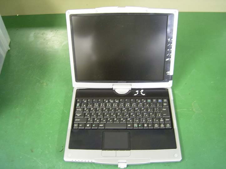
Click to zoom
Application Details
- Equipment Class
- DTS - Digital Transmission System
- Date of Grant
- Jun 15, 2003
- Application Purpose
- Original Equipment
- Date of Application
- Jun 15, 2003
- Equipment Note
- Tablet PC with WLAN
- Frequency Range
- 2412.00000000 - 2462.00000000
- Company
- Sharp Corporation
- Country
- Japan
Documents & Files
Document Text
Text extracted from the exhibit documents filed with the FCC. Open a document above to read the original.
Users Manual
i Notice for Users in the USA FCC Statement WARNING - FCC Regulations state that any unauthorized changes or modifications to this equipment not expressly approved by the manufacturer could void the user’s authority to operate this equipment. Note: This equipment has been tested and found to comply with the limits for a Class B digital device pursuant to Part 15 of the FCC Rules. These limits are designed to provide reasonable protection against harmful interference in a residential installation. This equipment generates, uses and can radiate radio frequency energy and, if not installed and used in accordance with the instructions, may cause harmful interference to radio communications. However, there is no guarantee that interference will not occur in a particular installation. If this equipment does cause harmful interference to radio or television reception, which can be determined by turning the equipments off and on, the user is encouraged to try to correct the interference by one or more of the following measures: • Reorient or relocate the receiving antenna. • Increase the distance between the equipment and receiver. • Connect the equipment into an outlet on a circuit different from that to which the receiver is connected. • Consult the dealer or an experienced radio/TV technician for help. A shielded I/F cable is required to insure compliance with FCC regulation for Class B computing equipment. * As an ENERGY STAR ® Partner, SHARP has determined that this product meets the ENERGY STAR ® guidelines for energy efficiency. Declaration of Conformity SHARP PERSONAL COMPUTER, PC-TN Series. This device complies with part 15 of the FCC rules. Operation is subject to the following conditions:(1) this device may not cause harmful interference, and (2) this device must accept any interference received, including interference that may cause undesired operation. Responsible Party: SHARP ELECTRONICS CORPORATION Sharp Plaza, Mahwah, New Jersey 07430-2135 TEL: 1-800-BE-SHARP ii About the Modem This equipment complies with Part 68 of FCC rules. On the bottom of this equipment is a label that contains, among other information, the FCC registration number and ringer equivalence number (REN) for this equipment. If requested, this information must be provided to the telephone company. The modem jack of this equipment complies with Sub-part F of Part 68 of FCC rules. The REN is used to determine the quantity of devices which may be connected to the telephone line. Excessive RENs on the telephone line may result in the devices not ringing in response to an incoming call. In most, but not all areas, the sum of the RENs should not exceed five (5.0). To be certain of the number of devices that may be connected to the line, as determined by the total RENs contact the telephone company to determine the maximum REN for the calling areas. If the terminal equipment causes harm to the telephone network, the telephone company will notify you in advance that temporary discontinuance of service may be required. But if advance notice isn't practical, the telephone company will notify the customer as soon as possible. Also, you will be advised of your right to file a complaint with the FCC if you believe it necessary. The telephone company may make changes in its facilities, equipment, operations, or procedures that could affect the operation of the equipment. If this happens, the telephone company will provide advance notice in order for you to make the necessary modifications in order to maintain uninterrupted service. If trouble is experienced with this equipment, please contact Sharp Electronics Corp. for repair and (or) warranty information (on the provided Consumer Limited Warranty sheet). If the trouble is causing harm to the telephone network, the telephone company may request you remove the equipment from the network until the problem is resolved. The equipment cannot be used on public coin service provided by the telephone company. Connection to Party Line Service is subject to state tariffs. (Contact the state public utility commission, public service commission or corporation commission for information.) The Telephone Consumer Protection Act of 1991 makes it unlawful for any person to use a computer or other electronic device, including fax machines, to send any message iii unless such message clearly contains in a margin at the top or bottom of each transmitted page or on the first page of the transmission, the date and time it is sent and an identification of the business or other entity, or other individual sending the message and the telephone number of the sending machine or such business, other entity, or individual. (The telephone number provided may not be a 900 number or any other number for which charges exceed local or long-distance transmission charges.) To program this information, refer to the manual of the communication software. For Wireless LAN Bundled Model FCC ID: APYNAR0050 This device complies with part 15 of the FCC rules. Operation is subject to the following conditions: (1) this device may not cause harmful interference, and (2) this device must accept any interference received, including interference that may cause undesired operation. FCC Radiation Exposure Statement The available scientific evidence does not show that any health problems are associated with using low power wireless devices. There is no proof, however, that these low power wireless devices are absolutely safe. Low power Wireless devices emit low levels of radio frequency energy (RF) in the microwave range while being used. Whereas high levels of RF can produce health effects (by heating tissue), exposure to low level RF that does not produce heating effects causes no known adverse health effects. Some studies have suggested that some biological effects might occur, but such findings have not been confirmed by additional research. This device has been tested and found to comply with the Federal Communications Com…
Text truncated - open the document above for the full version.
Cover Letter(s)
American Telecommunications Certification Body Inc. 6731 Whittier Ave, McLean, VA 22101 May 29, 2003 RE: FCC ID: APYNAR0050_ATCB000471 Attention: Yoshiaki Iwasa / Yukari Ito I have a few comments on this Application. 1. Please note that the FCC ID number on the sample label does not match the ID number in the report, 731, confidentiality request and other application documents. The report states the FCC ID is APYNAR0050 while the FCC ID sample label state it is APRNAR0050. Please correct the application documents to have the same FCC ID number. Please advise as to the proper FCC ID number. 2. Please note that your conducted data tables are not accurate. They only show compliance to the QP limits. While a device is considered compliant if the QP is under the average limit, the margin must still be compared to that which yields the least margin. For example, in the conducted data table on page 17 of the report you incorrectly show only the QP limit being met. The AV limit is only compliant by 2.8dB. In lieu of actual averaged measurements, this QP reading compared to the average limit is the margin that needs to be reported. This applies to all of your conducted data tables. Please provide a report showing the least margin in accordance with the rules. 3. Please note that much of the information on the schematics did not come through. The pin designations, chip signal names etc are blank. Perhaps this is due to Asian fonts or some other non translatable problem. Please provide readable schematics. 4. Dennis Ward mailto:[email protected] The items indicated above must be submitted before processing can continue on the above referenced application. Failure to provide the requested information may result in application termination. Correspondence should be considered part of the permanent submission and may be viewed from the Internet after a Grant of Equipment Authorization is issued. Please do not respond to this correspondence using the email reply button. In order for your response to be processed expeditiously, you must submit your documents through the AmericanTCB.com website. Also, please note that partial responses increase processing time and should not be submitted. Any questions about the content of this correspondence should be directed to the sender.
Cover Letter(s)
A- PEX INTERNATIONAL CO., LTD. □HEAD OFFICE 4383-326 Asama-cho, Ise-shi, Mie-ken 516-0021 Japan TEL:0596-24-6717/FAX:0596-24-8020 Date: 6 June, 2003 RE: Sharp Corporation FCC ID: APYNAR0050 Dear Mr. Dennis Ward, Regarding the above referenced application, please find our reply to the remaining comments to your inquiry dated: May 29, 2003 1) The proper FCC ID number is the one on application documents. We correct FCC ID number on label drawing. Please find uploaded “Revised Label Drawing.” 2) The least margin is 12.8dB (0.1500MHz) on page 17 of the test report. The result is 53.2dBuV and the margin to AV is 2.8dB. The measurement uncertainty for this test was +/- 1.3dB, as shown on page 6 of test report. The margin to AV is more than the uncertainty, and thus we conducted QP only. 3) Please find uploaded “Revised Schematics.” We hope the above reply is satisfactory. If any problems, please let us know. Best regards, Yukari Ito (Ms.) UL Apex Co., Ltd.
External Photos
Sharp Corporation FCC ID: APYNAR0050 External Photo Sharp Corporation FCC ID: APYNAR0050 Sharp Corporation FCC ID: APYNAR0050
ID Label/Location Info
Location of FCC ID Label
Internal Photos
Sharp Corporation FCC ID: APYNAR0050 Internal Photo Top View of WLAN card with shield Top View of WLAN card without shield Sharp Corporation FCC ID: APYNAR0050 Bottom View of WLAN card Position of Antennas Sharp Corporation FCC ID: APYNAR0050 Position of WLAN card
Operational Description
Calexico Single Band Card Theory of Operation Overview The Intel® PRO/Wireless LAN 2100 miniPCI adapter implements the 802. 11b physical (RF) specificati on. It operates at 1, 2, 5.5, and 11 Mbps. The Mini PCI card uses a Complementary code keying (CCK) baseband and SA2400 IC for modulation, demodulation, spreading and despreading of the RF signal. LAN 2100 The Intel® PRO/Wireless LAN 2100 miniPCI adapter implements the 82531ME, 802.11b CCK Baseband, and the Philips SA2400 radio ICs . 82531ME MAC Baseband OFDM processor CCK Baseband Processor Antennas MINI PCI Interface SA2400 2.4 GHz Radio Chip Tx, Rx Figure 1: Simplified Block Diagram for the Intel® PRO/Wireless LAN 2100 miniPCI adapter Transmit mode: The “upper” Media Access Control (MAC) logic inside the 82531ME is used to send and receive packets and transfers data to/from the host computer via the miniPCI interface. The 85231ME communicates with the CCK BBP IC through a special parallel interface called the Host Bus (H-BUS) interface. This i nterface uses registers with double-synchronizing flip-flops on all communica tion signals to prevent any ti ming-related problems between the two ICs. The CCK BBP IC functions as a “lower” MAC for the 80211b standard. This IC is also used to generate differential, analog I/Q vo ltage levels. The transmit I/Q signals are generated by 10 bit DACs (while the rece ive I/Q signals are read by 8 bit ADCs). These voltage level signals are first converted to current levels by external resistors networks and then are up-converted inside the SA2400 to the desired transmitt ing frequency. An integrated 4 th order low-pass Butterworth 9.75MHz filt er is used in the up-converter section fo r spectral shaping and reconstruction filterin g. Figure 1: Detailed Block Diagram for the Intel® PRO/Wireless LAN 2100 miniPCI adapter (Red items are on back side of PCB) 82531ME BBP MAC miniPCI SA2400 2.45GHz Direct Conversion Radio 40 MHz 22 MHz CCK BBP Differential I and Q MAX2242 RF PA 2.4-2.5GHz LOW PASS FILTER DP2T RF SWITCH 2.45GHz BANDPASS FILTER LNA 6dB PAD 6dB PAD 2.45GHz BANDPASS FILTER BALUN BALUN EEPROM ISOLATOR Rx Tx LOW PASS FILTER 1.8VA 1.8VD 3.3V 3.3VA 1.8VD 3.3V 2.9VA 3.3VA 3.3VA 3.3V 2.9VA J5 J6 Transmit mode (cont’d): The SA2400 generates a differential RF signal at the desired operat ing frequency. Please note, that since this is a zero-IF typ e design, there are no Intermediate Frequency (IF) stages used. The SA2400 beats the IQ modulation directly up to the appropriate frequency of ope ration set by its built-in PLL. Upon exiting from the SA2400, this differential signal is transformed to single ended form using a discrete balu n circuit. The balun is designed to convert 100ohm differential impedance to 50ohms single ended impedance while also supplying proper bias voltage to the output stage of the Philips IC. From the output of the balun, the signal is band pass filtered with a ceramic 2400 to 2500MHz Band Pas s filter (BPF). This filtered signal is then attenuated using a 6dB, 50ohm resi stive pi-attenuator network. A MAXIM 2242 chip scale RF Power am plifier (PA) IC is used to amplify the low level filtered compos ite signal to approximately +20dBm levels. At the output of the PA, a ceramic 2400 to 2500MHz Low Pass Filter (LPF) is used to reduce harmonic content in the amplified si gnal. From this point the signal is routed through the single band anten na diversity switch to one of the two U.FL antennae connector s. A discrete logic IC (not shown in the diagram) is used to decode antennae switching information from the CCK BBP IC in order to correctly operat e the antenna switch. This IC is a 74LVC08 IC on the back of the PCB. An RF signal level of approx -5dBm at the output of the SA2400 IC can be expected to produce an amplified RF signal of approxim ately +16dBm at the antennae connectors. Receive mode: During receive; the signal is first routed through a ceramic 24 00 to 2500MHz Band Pass filter (BPF) and through a single transi stor, Low Noise Amplifier (LNA). The amplified and filtered signal is then attenuated via a 6dB, 50ohm resistive pi-attenuator network. A 50ohm to 100ohm integrated balun is then used to convert the single ended signal to a differential voltage which can be applied to the receive terminals on the SA2400 IC. The LNA and attenuator form an isolation network which is requir ed to isolate the low level Voltage Controlled Oscillator (VCO) frequency leakage from the antennae. An isolation network helps to reduce DC offsets that occur when switching antennae in diversity application s. Inside the SA2400, the received signal is first amplified with an Automatic Gain Controlled (AGC) amplifier and then mixed down in frequency (from RF to DC) using a quadrature IQ up/down mixer. From her e the downconverted signal is then low-pass filtered using Chebych ev 5 th order active filters. A DC cancellation mechanism is able to reduce DC offsets by 70dB hence clipping of the baseband signals can be avoided. The baseband IQ signals are transmitted differentially via current signal which are converted to voltage by the external resist or networks. These differential analog IQ voltage levels are read by the 6 bit ADCs inside of the CCK BBP IC. The CCK BBP IC is used to demodulate the IQ signals to produce packets of data whic h is communicated to the 82531ME upper MAC a nd onwards to the host computer via the miniPCI bus. SA2400 Radio The SA2400 from Philips is a fully integrated single IC RF transc eiver designed for 2.4 GHz wireless LAN applications. It is a direct conversion radio architecture device and combines a low-noise aut omatic gain control (AGC) amplif ier, receive and transmit filt ers, and input/output buffers into a single IC. 82531ME MAC and Baseband The 82531ME chip incorporates Media Access Control (MAC) logic, baseband processing functions, and a miniPCI interface, as well as Analog-to-Digital and Digital-to-Analog conver ters (ADC and DAC). This fully integrated d…
Text truncated - open the document above for the full version.
RF Exposure Info
Test report No. : 23FE0057-HO-2 Page : 2 of 67 Issued date : May 07,2003 FCC ID : APYNAR0050 UL Apex Co., Ltd. Head Office EMC Lab. 4383-326 Asama-cho, Ise-shi, Mie-ken 516-0021 JAPAN Telephone: +81 596 24 8116 Facsimile: +81 596 24 8124 CONTENTS PAGE SECTION 1 : Client information 3 SECTION 2 : Equipment under test (E.U.T.) 3 SECTION 3 : Requirements for compliance testing defined by the FCC 4 SECTION 4 : Dosimetric assessment setup 4 SECTION 5 : Test system specifications 7 SECTION 6 : Test setup of EUT 8 SECTION 7 : Measurement uncertainty 10 SECTION 8 : Simulated tissue liquid parameter 11 SECTION 9 : System validation data 12 SECTION 10 : Evaluation procedure 13 SECTION 11 : Exposure limit 14 SECTION 12 : SAR Measurement results 15 SECTION 13 : Equipment & calibration information 16 SECTION 14 : References 17 SECTION 15 : APPENDIX 17 APPENDIX 1 : Photographs of test setup APPENDIX 2 : SAR Measurement data APPENDIX 3 : Validation Measurement data APPENDIX 4 : System Validation Dipole (D2450V2,S/N: 713) APPENDIX 5 : Dosimetric E-Field Probe Calibration(ET3DV6,S/N: 1684) Test report No. : 23FE0057-HO-2 Page : 3 of 67 Issued date : May 07,2003 FCC ID : APYNAR0050 UL Apex Co., Ltd. Head Office EMC Lab. 4383-326 Asama-cho, Ise-shi, Mie-ken 516-0021 JAPAN Telephone: +81 596 24 8116 Facsimile: +81 596 24 8124 SECTION 1 : Client information Company Name : Sharp Corporation Brand Name : SHARP Address : 492 Minosho-cho, Yamatokoriyama-shi, Nara 639-1186, Japan Telephone Number : +81-743-55-7344 Facsimile Number : +81-743-52-0004 Contact Person : Masao Mikamo SECTION 2 : Equipment under test (E.U.T.) 2.1 Identification of E.U.T. APPLICANT : Sharp Corporation Type of Equipment : TabletPC Model No. : PC-TN10W Serial No. : CG-0001 Rating : DC3.3V Country of Manufacture : Japan Receipt Date of Sample : April 4,2003 Condition of EUT : Enginieering prototype Tx Frequency : 2412MHz~2462MHz Modulation : DSSS [DBPSK,DQBSK,CCK] Max.Output Power Tested : 16.3dBm Peak Conducted Antenna Type : Diversity antenna (λ/4 fixed Type) Position of Antenna : See Photograph of right Battery option : Only one model with EUT Category Identified : Portable device Antenna of W-LAN (display top) Antenna of W-LAN (display under) Test report No. : 23FE0057-HO-2 Page : 4 of 67 Issued date : May 07,2003 FCC ID : APYNAR0050 UL Apex Co., Ltd. Head Office EMC Lab. 4383-326 Asama-cho, Ise-shi, Mie-ken 516-0021 JAPAN Telephone: +81 596 24 8116 Facsimile: +81 596 24 8124 SECTION 3 : Requirements for compliance testing defined by the FCC The US Federal Communications Commission has released the report and order “Guidelines for Evaluating the Environmental Effects of RF Radiation", ET Docket No. 93-62 in August 1996. The order requires routine SAR evaluation prior to equipment authorization of portable transmitter devices, including portable telephones. For consumer products, the applicable limit is 1.6 mW/g for an uncontrolled environment and 8.0 mW/g for an occupational/controlled environment as recommended by the ANSI/IEEE standard C95.1-1992. According to the Supplement C of OET Bulletin 65 “Evaluating Compliance with FCC Guide-lines for Human Exposure to Radio frequency Electromagnetic Fields", released on Jun 29, 2001 by the FCC, the device should be evaluated at maximum output power (radiated from the antenna) under “worst-case” conditions for normal or intended use, incorporating normal antenna operating positions, device peak performance frequencies and positions for maximum RF energy coupling. 1 Specific Absorption Rate (SAR) is a measure of the rate of energy absorption due to exposure to an RF transmitting source (wireless portable device). 2 IEEE/ANSI Std. C95.1-1992 limits are used to determine compliance with FCC ET Docket 93-62. SECTION 4 : Dosimetry assessment setup These measurements were performed with the automated near-field scanning system DASY3 from Schmid & Partner Engineering AG (SPEAG). The system is based on a high precision robot (working range greater than 0.9 m), which positions the probes with a positional repeatability of better than +/- 0.02 mm. Special E- and H-field probes have been developed for measurements close to material discontinuity, the sensors of which are directly loaded with a Schottky diode and connected via highly resistive lines to the data acquisition unit. The SAR measurements were conducted with the dosimetry probe ET3DV6, SN: 1684 (manufactured by SPEAG), designed in the classical triangular configuration and optimized for dosimetric evaluation. The probe has been calibrated according to the procedure described in [2] with accuracy of better than +/-10%. The spherical isotropy was evaluated with the procedure described in [3] and found to be better than +/-0.25 dB. The phantom used was the SAM Twin Phantom as described in FCC supplement C, IEE P1528 and CENELEC EN50361. Test report No. : 23FE0057-HO-2 Page : 5 of 67 Issued date : May 07,2003 FCC ID : APYNAR0050 UL Apex Co., Ltd. Head Office EMC Lab. 4383-326 Asama-cho, Ise-shi, Mie-ken 516-0021 JAPAN Telephone: +81 596 24 8116 Facsimile: +81 596 24 8124 4.1 Configuration and peripherals The DASY3 system for performing compliance tests consist of the following items: 1. A standard high precision 6-axis robot (Stäubli RX family) with controller and software. 2. An arm extension for accommodating the data acquisition electronics (DAE). 3. A dosimetric probe, i.e., an isotropic E-field probe optimized and calibrated for usage in tissue simulating liquid. The probe is equipped with an optical surface detector system. 4. A data acquisition electronic (DAE), which performs the signal amplification, signal multiplexing, AD-conversion, offset measurements, mechanical surface detection, collision detection, etc. The unit is battery powered with standard or rechargeable batteries. The signal is optically transmitted to the EOC. 5. A unit to operate the optical surface detector, which is connected to the EOC. 6. The Electro-optical coupler (E…
Text truncated - open the document above for the full version.
RF Exposure Info
Test report No. : 23FE0057-HO-2 Page : 28 of 67 Issued date : May 07,2003 FCC ID : APYNAR0050 UL Apex Co., Ltd. Head Office EMC Lab. 4383-326 Asama-cho, Ise-shi, Mie-ken 516-0021 JAPAN Telephone: +81 596 24 8116 Facsimile: +81 596 24 8124 APPENDIX 2 : SAR Measurement data
RF Exposure Info
Test report No. : 23FE0057-HO-2 Page : 42 of 67 Issued date : May 07,2003 FCC ID : APYNAR0050 UL Apex Co., Ltd. Head Office EMC Lab. 4383-326 Asama-cho, Ise-shi, Mie-ken 516-0021 JAPAN Telephone: +81 596 24 8116 Facsimile: +81 596 24 8124 APPENDIX 3 : Validation Measurement data
RF Exposure Info
Test report No. : 23FE0057-HO-2 Page : 44 of 67 Issued date : May 07,2003 FCC ID : APYNAR0050 UL Apex Co., Ltd. Head Office EMC Lab. 4383-326 Asama-cho, Ise-shi, Mie-ken 516-0021 JAPAN Telephone: +81 596 24 8116 Facsimile: +81 596 24 8124 APPENDIX 4 : System Validation Dipole (D2450V2,S/N: 713)
RF Exposure Info
Test report No. : 23FE0057-HO-2 Page : 54 of 67 Issued date : May 07,2003 FCC ID : APYNAR0050 UL Apex Co., Ltd. Head Office EMC Lab. 4383-326 Asama-cho, Ise-shi, Mie-ken 516-0021 JAPAN Telephone: +81 596 24 8116 Facsimile: +81 596 24 8124 APPENDIX 5 : Dosimetric E-Field Probe Calibration(ET3DV6,S/N: 1684)
Test Report
Testreport No. : 23FE0057-HO-1 Page : 5 of 41 Revised date : Jun 9, 2003 FCC ID : APYNAR0050 UL Apex Co., Ltd. SECTION 3: Test specification, procedures & results 3.1 Test Specification Test Specification : FCC Part15 Subpart C Title : FCC 47CFR Part15 Radio Frequency Device Subpart C Intentional Radiators Section 15.207 Conducted limits Section 15.247 Operation within the bands 902-928MHz, 2400-2483.5MHz, and 5725-5850MHz 3.2 Procedures and results No. Item Test Procedure Specification Remarks Deviation Worst margin Results 1 Conducted emission ANSI C63.4:2001 Section 15.207 - N/A 2.8dB, (AV) 12.8dB, (QP) 0.1500MHz, L1 Complied 2 6dB Bandwidth ANSI C63.4:2001 Section 15.247(a)(2)Conducted N/A 7.655MHz 2412MHz Complied 3 Maximum Peak Output Power ANSI C63.4:2001 Section 15.247(b)(3)Conducted N/A 2435.1MHz 6.9dB Complied 4 Out of Band Emission ANSI C63.4:2001 Section 15.247 (c) Conducted/ Radiated N/A 8.7dB(PK) 14622.0MHz Complied 5 Restricted Band Edges ANSI C63.4:2001 Section 15.247 (c) Conducted N/A - Complied 6 Power Density ANSI C63.4:2001 Section 15.247 (d) Conducted N/A 8.5dB 2437.5MHz Complied These tests were also referred to FCC 97-114 “Guidance on Measurement for Direct Sequence Spread Spectrum Systems. 3.3 Additions to Standards No addition, deviation or exclusion has been made from standards. 3.4 Confirmation UL Apex Co, Ltd. hereby confirms that E.U.T., in the configuration tested, complies with the specifications FCC Part 15 Subpart C Section 15.207 and 15.247. Head Office EMC Lab. 4383-326 Asama-cho, Ise-shi, Mie-ken 516-0021 JAPAN Telephone : +81 596 24 8116 Facsimile : +81 596 24 8124 MF060b(10.04.03)
Contact Information
Applicant
Taihei Ohtsuka(Deputy Division Manager, ESG & Q promotion unit)
Technical Contact
UL Apex Co., Ltd. +Yoshiaki Iwasa
81-596-24-8116
4383-326 Asama-cho, · Ise-shi, Mie-ken · Japan
Test Firm
UL Apex Co., Ltd.Toshihiro Ikegami
Technical Specifications
| # | Rule Parts | Frequency Range | Power Output |
|---|---|---|---|
| 1 | 15C | 2.41 GHz - 2.46 GHz | 41.00 mW |
Other Applications from Sharp Corporation
APYHRO00343
Aug 17, 2026Smartphone
Equipment Class
DTS - Digital Transmission SystemAPYHRO00342
Jul 29, 2026Smart phone
Equipment Class
DXX - Part 15 Low Power Communication Device TransmitterAPYHRO00341
May 28, 2026Smart phone
Equipment Class
DTS - Digital Transmission SystemAPYHRO00340
Dec 01, 2025BT remote control
Equipment Class
DTS - Digital Transmission SystemAPYHRO00339
Sep 17, 2025Smart phone
Equipment Class
NII - Unlicensed National Information Infrastructure TX