APYNAR0062Wireless PDA
Sharp Corporation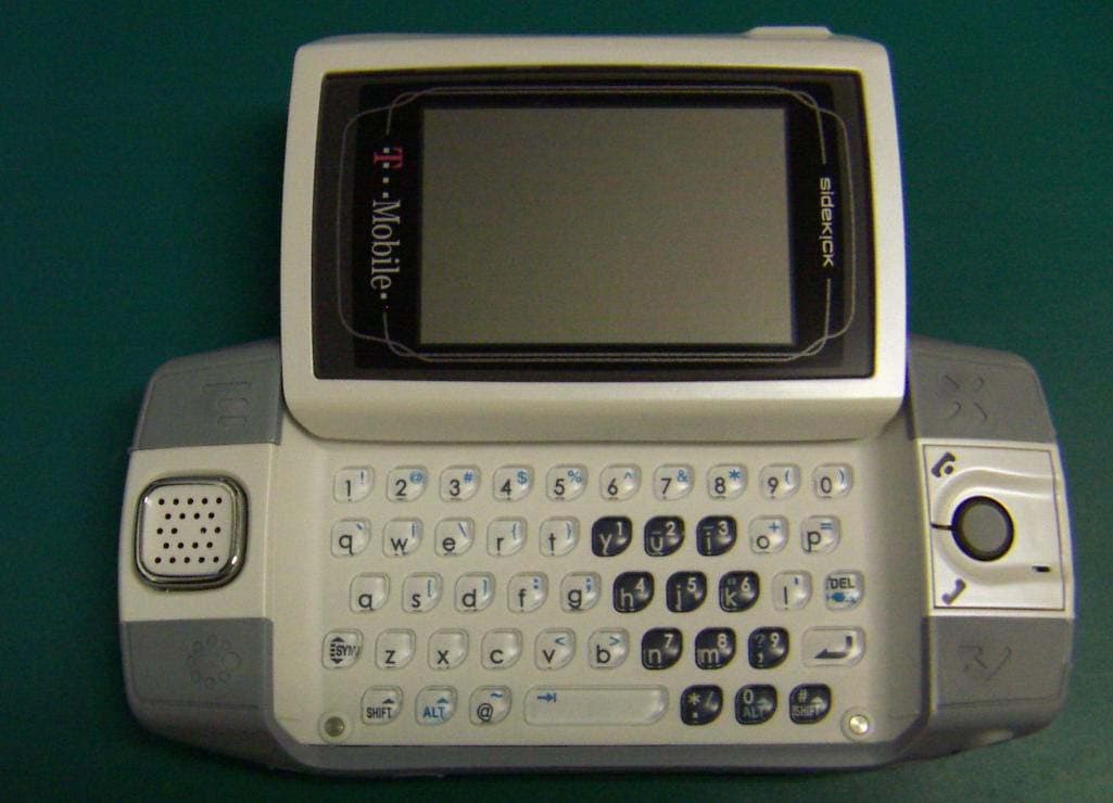
Click to zoom
Application Details
- Equipment Class
- PCE - PCS Licensed Transmitter held to ear
- Date of Grant
- Jan 18, 2007
- Application Purpose
- Original Equipment
- Date of Application
- Jan 17, 2007
- Equipment Note
- Wireless PDA
- Frequency Range
- 824.20000000 - 848.80000000
- Company
- Sharp Corporation
- Country
- Japan
Documents & Files
Document Text
Text extracted from the exhibit documents filed with the FCC. Open a document above to read the original.
Users Manual
Check Your Voice Mail 1 Press JUMP to go to the Jump screen, then press the trackball to open the Phone application. 2 Press and hold the 1 key (the speed dial shortcut assigned to voice mail) to call your voice mailbox. 3 Follow the prompts to retrieve your messages.* 4 To hang up, select , or press END CALL . To check your voice mail from another phone, call your mobile number. Let it ring through to voice mail, then press the (*) star key to interrupt the greeting. At the prompt, type your password. Change Your Phone Ringtone 1 Press JUMP to go to the Jump screen, then press the trackball to open the Phone application. 2 Press MENU to open the Phone menu. Select Settings > General. 3 Highlight the Incoming phone call ring pop-up menu, then press the trackball. The menu reveals the ringtone categories. First highlight a category, then press the trackball to open the ringtones submenu. As you scroll through the songs, you can preview each song by hovering over it for a few seconds. 4 When you have decided on a ringtone, press the trackball to select it. Press DONE to assign your new ringtone. Assign caller-specific ringtones from the Address Book > Contact Details pages. * Airtime charges apply. Using the Applications 39 Import Contacts from Your SIM Card If you already have a SIM card from T-Mobile, you can import the phone numbers you have stored on the SIM card into your device’s Address Book. First, insert the SIM card with the contacts into your device, then: 1 Press JUMP to go to the Jump screen. Scroll to highlight Address Book, then press the trackball to open the application. 2 Press MENU to open the menu. Select Settings > Import SIM Contacts . 3 The SIM Import dialog will alert you when the import is complete. Text Messages Send a Text Message 1 Press JUMP to go to the Jump screen. Scroll to highlight Text Messages, then press the trackball to open the application. 2 Press MENU to open the menu. New Message is selected by default; press the trackball to open the Compose screen . 3 Address your message using the recipient’s 10-digit phone number, or start typing their name to bring up Address Book matches. Add more recipients by typing a comma (,) or semicolon (;) in the To field. 4 Use the trackball to scroll to the message body; type your message or use one of the Prewritten Messages by selecting the button. Add Smileys by selecting the button. To attach a vCard, press MENU and select Attach vCard. Select a contact from the list that appears to attach it to your text message. If your message is larger than the limit for a single text message (approximately 160 characters), the message will be sent in parts. (When received, it will appear as one message.) 5 When ready to send, either select the Send button at the bottom of the Compose screen, or press MENU + M.* * Separate charges apply to send and receive text messages. 40 Using the Applications Web Browser Browse the Web 1 Press JUMP to go to the Jump screen. Scroll to highlight Web Browser, then press the trackball to open the application. 2 Start typing the address of the Web page you wish to visit. The Go To dialog box opens automatically, showing the address you are typing. 3 The characters you type appear in the top field of the Go To dialog box. Possible URL matches, and the option to search for the text you type, appear in the drop-down menu. 4 To go to a Web page, you can either finish typing the complete URL in the Go To dialog box then press Return; or, roll the trackball to highlight a suggested URL in the drop-down menu, then press the trackball. To open Web pages faster, press MENU and select Settings. Scroll down the Settings screen and clear the “Show Pictures” check box. Bookmark a Web Page 1 Open the Web page you want to bookmark. 2 Press MENU + N to open the Add Bookmark dialog box. 3 Edit the bookmark name if you wish, verify the URL and select a folder in which to store the bookmark from the Folder pop-up menu. (If you select New Folder, you’ll be prompted to give the folder a name.) 4 Press DONE to save the bookmark. Using the Applications 41 Email Send an Email Message 1 Press JUMP to go to the Jump screen. Scroll to highlight Email, then press the trackball to open the application. 2 Press MENU to open the menu. New Message is selected by default; press the trackball to go to the Compose screen. 3 The text cursor is in the To field; type the name or email address of the person to whom you wish to send an email. If you type a name, the Address Book will try to pull the correct email address from your contact data. Add more To fields by typing a comma (,) or semicolon (;). 4 Scroll to the Subject field and type the subject of your email. 5 Scroll to the message body and type your message. To delete text in the forward direction, press the SHIFT + DEL keys together. To delete the current line of text, press the ALT + DEL keys together. 6 When ready to send, either select the Send button at the bottom of the Compose screen, or press MENU + M. Receive Email from External Accounts When you register your device account, you automatically receive an email account that you can use immediately on either your device or the Email application on the Desktop Interface. In addition, you can receive email from up to three external POP3 or IMAP email accounts. At this time, email from MSN Hotmail ® and email servers that are protected by a firewall do not allow email to be received by other servers. You can, however, check some Internet email accounts by using the Web Browser, as described in “Receive Email Using Your Device’s Web Browser” on page 45. 42 Using the Applications The instructions below explain how to use your device to receive email from external accounts. Note that you can also set up accounts from the Email application on the Desktop Interface. 1 Press JUMP to go to the Jump screen. Scroll to highlight Email, then press the trackball to open the application. 2 Press MENU then select Settings > …
Text truncated - open the document above for the full version.
Cover Letter(s)
American Telecommunications Certification Body Inc. 6731 Whittier Ave, McLean, VA 22101 December 19, 2006 RE: FCC ID: APYNAR0062_ATCB004354 Attention: Kijiro Kumagai / Hironobu Shimoji I have a few comments on this Application. Please note that further comments may arise in response to answers provided to the questions below. 1. Please note that you have marked several exhibits as temporary confidentiality but have not provided a request for temporary confidentiality. If temporary confidentiality is being requested, please provide the request letter and list each appropriate exhibit for which temporary confidentiality is being requested. 2. Please note that the tune up procedure required by the FCC is not dependent upon end user ability to tune the device nor is it dependent upon the ability of the integrator to tune the device. Please note that the tune up procedure required by the FCC in accordance with 47CFR2.1033 deals with the required factory alignment procedures. Please provide the factory tune up procedures for the GSM module. 3. Please note that the report lists GPRS and PCS1900. Please note that GMS and GPRS are both GXW emissions designators whereas EGPRS (Edge technology) is G7W. The 731 lists G7W as an emissions designator. Please confirm if the designation in the report “GPRS” is in fact EDGE technology (G7W). If it is, please correct the report to indicate EDGE G7W technology. 4. Please confirm if the GPRS listed in the SAR report is intended to indicate EDGE technology (G7W designator). If so. Please correct the report to properly indicate EDGE technology. Dennis Ward mailto:[email protected] The items indicated above must be submitted before processing can continue on the above referenced application. Failure to provide the requested information may result in application termination. Correspondence should be considered part of the permanent submission and may be viewed from the Internet after a Grant of Equipment Authorization is issued. Please do not respond to this correspondence using the email reply button. In order for your response to be processed expeditiously, you must submit your documents through the AmericanTCB.com website. Also, please note that partial responses increase processing time and should not be submitted. Any questions about the content of this correspondence should be directed to the sender.
External Photos
External Photo
ID Label/Location Info
ACTUAL SIZE SHARP CONFIDENTIAL S1 IMEI LABEL ARTWORK 17,NOV.2006 SHARP CONFIDENTIAL S1 Regulation LABEL ARTWORK 21,NOV.2006 ACTUAL SIZE
Internal Photos
Internal Photo Photo of RF Module Antenna RF Module
RF Exposure Info
Test report No. : 26LE0301-HO-E Page : 2 of 97 Issued date : December 6, 2006 FCC ID : APYNAR0062 UL Apex Co., Ltd. Head Office EMC Lab. 4383-326 Asama-cho, Ise-shi, Mie-ken 516-0021 JAPAN Telephone: +81 596 24 8116 Facsimile: +81 596 24 8124 SECTION 1 : Client information ........................................................................................................................................................................ 3 SECTION 2 : Equipment under test (E.U.T.) .................................................................................................................................................... 3 2.1 Identification of E.U.T. ...................................................................................................................................... 3 2.2 Product Description............................................................................................................................................ 4 SECTION 3 : Test standard information ........................................................................................................................................................... 5 3.1 Requirements for compliance testing defined by the FCC ................................................................................. 5 3.2 Exposure limit .................................................................................................................................................... 6 SECTION 4 : Test result ...................................................................................................................................................................................... 7 4.1 Result of Max. SAR value.................................................................................................................................. 7 4.2 Test Location...................................................................................................................................................... 7 SECTION 5 : Operation of E.U.T. during testing ............................................................................................................................................. 8 5.1 Operating modes ................................................................................................................................................ 8 5.2 Description of the head test setup....................................................................................................................... 9 5.3 Method of measurement (Head SAR) ................................................................................................................ 10 5.4 Description of the Body-worn test setup and Method ........................................................................................ 10 SECTION 6 : Test surrounding .......................................................................................................................................................................... 11 6.1 Measurement uncertainty ................................................................................................................................... 11 SECTION 7 : Confirmation before testing......................................................................................................................................................... 12 7.1 Output Power Measurement results.................................................................................................................... 12 SECTION 8 : Measurement results .................................................................................................................................................................... 14 8.1 Head 850MHz SAR ........................................................................................................................................... 14 8.2 Body-worn 850MHz SAR.................................................................................................................................. 15 8.3 Head 1900MHz SAR ......................................................................................................................................... 16 8.4 Body-worn 1900MHz SAR................................................................................................................................ 17 APPENDIX 1 : Photographs of test setup ........................................................................................................................... 18 APPENDIX 2 : SAR Measurement data ............................................................................................................................. 26 1. Evaluation procedure .......................................................................................................................................... 27 2. Measurement data (GSM 850)............................................................................................................................ 28 3. Measurement data (PCS1900) ............................................................................................................................ 41 APPENDIX 3 : Test instruments.......................................................................................................................................... 54 1. Equipment used .................................................................................................................................................. 55 2. Dosimetry assessment setup ............................................................................................................................... 56 3. Configuration and peripherals ............................................................................................................................ 57 4. System components .................................................................................................................…
Text truncated - open the document above for the full version.
RF Exposure Info
Test report No. : 26LE0301-HO-E Page : 26 of 97 Issued date : December 6, 2006 FCC ID : APYNAR0062 UL Apex Co., Ltd. Head Office EMC Lab. 4383-326 Asama-cho, Ise-shi, Mie-ken 516-0021 JAPAN Telephone: +81 596 24 8116 Facsimile: +81 596 24 8124 APPENDIX 2 : SAR Measurement data Test report No. : 26LE0301-HO-E Page : 27 of 97 Issued date : December 6, 2006 FCC ID : APYNAR0062 UL Apex Co., Ltd. Head Office EMC Lab. 4383-326 Asama-cho, Ise-shi, Mie-ken 516-0021 JAPAN Telephone: +81 596 24 8116 Facsimile: +81 596 24 8124 1. Evaluation procedure The evaluation was performed with the following procedure: Step 1: Measurement of the E-field at a fixed location above the ear point or central position of flat phantom was used as a reference value for assessing the power drop. Step 2: The SAR distribution at the exposed side of head or body position was measured at a distance of each device from the inner surface of the shell. The area covered the entire dimension of the antenna of EUT and the horizontal grid spacing was 20 mm x 20 mm . Based on these data, the area of the maximum absorption was determined by spline interpolation. Step 3: Around this point found in the Step 2 (area scan) , a volume of 30mm x 30mm x 30mm was assessed by measuring 7 x 7 x 7 points. And for any secondary peaks found in the Step2 which are within 2dB of maximum peak and not with this Step3 (Zoom scan) is repeated. On the basis of this data set, the spatial peak SAR value was evaluated under the following procedure: (1). The data at the surface were extrapolated, since the center of the dipoles is 1mm away from the tip of the probe and the distance between the surface and the lowest measuring point is 1.3 mm. The extrapolation was based on a least square algorithm [4]. A polynomial of the fourth order was calculated through the points in z-axes. This polynomial was then used to evaluate the points between the surface and the probe tip. (2). The maximum interpolated value was searched with a straightforward algorithm. Around this maximum the SAR values averaged over the spatial volumes (1 g or 10 g) were computed by the 3D-Spline interpolation algorithm. The 3D- Spline is composed of three one-dimensional splines with the “Not a knot"-condition (in x, y and z-directions) [4], [5]. The volume was integrated with the trapezoidal-algorithm. One thousand points (10 x 10 x 10) were interpolated to calculate the average. (3). All neighboring volumes were evaluated until no neighboring volume with a higher average value was found. Step 4: Re-measurement of the E-field at the same location as in Step 1. Test report No. : 26LE0301-HO-E Page : 28 of 97 Issued date : December 6, 2006 FCC ID : APYNAR0062 UL Apex Co., Ltd. Head Office EMC Lab. 4383-326 Asama-cho, Ise-shi, Mie-ken 516-0021 JAPAN Telephone: +81 596 24 8116 Facsimile: +81 596 24 8124 2. Measurement data (GSM 850) PV150/ Left Head /Cheek / GSM / 190ch(836.6MHz) Crest factor:8.3 Medium parameters used: f = 835 MHz; σ = 0.87 mho/m; ε r = 40.6; ρ = 1000 kg/m 3 Phantom section: Left Section Measurement Standard: DASY4 (High Precision Assessment) DASY4 Configuration: Probe: EX3DV3 - SN3507; ConvF(10.62, 10.62, 10.62); Calibrated: 2006/05/26 Sensor-Surface: 2mm (Mechanical Surface Detection) Electronics: DAE3 Sn509; Calibrated: 2006/06/15 Phantom: SAM 1196 Measurement SW: DASY4, V4.6 Build 23; Postprocessing SW: SEMCAD, V1.8 Build 160 Area Scan (71x111x1): Measurement grid: dx=20mm, dy=20mm Maximum value of SAR (interpolated) = 0.620 mW/g Zoom Scan (7x7x7)/Cube 0: Measurement grid: dx=5mm, dy=5mm, dz=5mm Reference Value = 19.5 V/m; Power Drift = 0.020 dB Peak SAR (extrapolated) = 0.663 W/kg SAR(1 g) = 0.515 mW/g; SAR(10 g) = 0.378 mW/g Maximum value of SAR (measured) = 0.602 mW/g Test Date = 12/04/06 Ambient Temperature = 25.0 degree C. Liquid Temperature = Before 23.3 degree C. , After 23.3 degree C. Test report No. : 26LE0301-HO-E Page : 29 of 97 Issued date : December 6, 2006 FCC ID : APYNAR0062 UL Apex Co., Ltd. Head Office EMC Lab. 4383-326 Asama-cho, Ise-shi, Mie-ken 516-0021 JAPAN Telephone: +81 596 24 8116 Facsimile: +81 596 24 8124 PV150/ Left Head /Tilt / GSM / 190ch(836.6MHz) Crest factor:8.3 Medium parameters used: f = 835 MHz; σ = 0.87 mho/m; ε r = 40.6; ρ = 1000 kg/m 3 Phantom section: Left Section Measurement Standard: DASY4 (High Precision Assessment) DASY4 Configuration: Probe: EX3DV3 - SN3507; ConvF(10.62, 10.62, 10.62); Calibrated: 2006/05/26 Sensor-Surface: 2mm (Mechanical Surface Detection) Electronics: DAE3 Sn509; Calibrated: 2006/06/15 Phantom: SAM 1196 Measurement SW: DASY4, V4.6 Build 23; Postprocessing SW: SEMCAD, V1.8 Build 160 Area Scan (71x111x1): Measurement grid: dx=20mm, dy=20mm Maximum value of SAR (interpolated) = 0.373 mW/g Zoom Scan (7x7x7)/Cube 0: Measurement grid: dx=5mm, dy=5mm, dz=5mm Reference Value = 17.3 V/m; Power Drift = 0.055 dB Peak SAR (extrapolated) = 0.482 W/kg SAR(1 g) = 0.288 mW/g; SAR(10 g) = 0.180 mW/g Maximum value of SAR (measured) = 0.378 mW/g Test Date = 12/04/06 Ambient Temperature = 25.0 degree C. Liquid Temperature = Before 23.3 degree C. , After 23.3 degree C. Test report No. : 26LE0301-HO-E Page : 30 of 97 Issued date : December 6, 2006 FCC ID : APYNAR0062 UL Apex Co., Ltd. Head Office EMC Lab. 4383-326 Asama-cho, Ise-shi, Mie-ken 516-0021 JAPAN Telephone: +81 596 24 8116 Facsimile: +81 596 24 8124 PV150/ Right Head /Cheek / GSM / 190ch(836.6MHz) Crest factor:8.3 Medium parameters used: f = 835 MHz; σ = 0.87 mho/m; ε r = 40.6; ρ = 1000 kg/m 3 Phantom section: Right Section Measurement Standard: DASY4 (High Precision Assessment) DASY4 Configuration: Probe: EX3DV3 - SN3507; ConvF(10.62, 10.62, 10.62); Calibrated: 2006/05/26 Sensor-Surface: 2mm (Mechanical Surface Detection) Electronics: DAE3 Sn509; Calibrated: 2006/06/15 Phantom: SAM 1196 Measurement SW: DASY4, V4.6 Build 23; Postprocessing SW: SEMCAD, V1.8 Build 160 Area Scan (71x111x1): Measurement grid: dx=20mm, dy=20mm Maximum value of SAR (interpolated) = 0.670 m…
Text truncated - open the document above for the full version.
RF Exposure Info
Test report No. : 26LE0301-HO-E Page : 54 of 97 Issued date : December 6, 2006 FCC ID : APYNAR0062 UL Apex Co., Ltd. Head Office EMC Lab. 4383-326 Asama-cho, Ise-shi, Mie-ken 516-0021 JAPAN Telephone: +81 596 24 8116 Facsimile: +81 596 24 8124 APPENDIX 3 : Test instruments Test report No. : 26LE0301-HO-E Page : 55 of 97 Issued date : December 6, 2006 FCC ID : APYNAR0062 UL Apex Co., Ltd. Head Office EMC Lab. 4383-326 Asama-cho, Ise-shi, Mie-ken 516-0021 JAPAN Telephone: +81 596 24 8116 Facsimile: +81 596 24 8124 1. Equipment used Calibration Control No. Name of Equipment Manufacture Model number Serial number Last Cal due date MRENT-33 Power sensor Anritsu MA2411B 011513 2006/04/25 2007/04/24 MRENT-36 Power Meter Anritsu ML2496A 6K00003393 2006/04/25 2007/04/24 MAT-22 Attenuator(10dB) DC-18GHz Orient Microwave BX10-0476-00 - 2006/03/18 2007/03/17 MPM-08 Power Meter Anritsu ML2495A 6K00003338 2006/09/20 2007/09/19 MPSE-11 Power sensor Anritsu MA2411B 011737 2006/09/20 2007/09/19 MAT-21 Attenuator(20dB)(above1GHz) HIROSE ELECTRIC CO.,LTD. AT-120 901247 2006/01/10 2007/01/09 MAT-23 Attenuator(10dB) DC-18GHz Orient Microwave BX10-0476-00 - 2006/03/18 2007/03/17 APDDC02 Dual Directional Coupler Hewlett Packard 778D 16605 N/A N/A APDDC03 Dual Directional Coupler Hewlett Packard 772D 2839A0016 N/A N/A MSG-05 Signal Genelator Agilent E4438C MY45090353 2006/06/03 2007/06/02 MRFA-08 Pre Amplifier TSJ TCBP0206 - 2006/03/11 2007/3/10 MNA-01 Network Analyzer Agilent E8358A US41080381 2006/02/10 2009/02/09 MPB-03 Dosimetric E-Field Probe Schmid&Partner Engineering AG EX3DV3 3507 2006/05/26 2007/05/25 MDAE-01 Data Acquisition Electronics Schmid&Partner Engineering AG DAE3 V1 509 2006/06/15 2007/06/14 MSTW-16 SAR measurement System Schmid&Partner Engineering AG DASY4 I021834 N/A N/A MDA-05 900MHz System Validation Dipole Schmid&Partner Engineering AG D900V2 174 2006/07/06 2008/07/05 MDA-06 1800MHz System Validation Dipole Schmid&Partner Engineering AG D1800V2 214 2005/07/14 2007/07/13 MPF-01 Schmid&Partner Engineering AG 2.0mm Flat Phantom V4.3L 1005 N/A N/A N/A MOS-05 Thermo-Hygrometer Custom CTH-190 810201 2006/04/25 2008/04/24 MOS-10 Digtal thermometer HANNA Checktemp-2 MOS-10 2005/03/07 2007/03/06 - Head 900MHz N/A N/A N/A Daily check Target value ± 5% - Head 1800MHz N/A N/A N/A Daily check Target value ± 5% - Body 900MHz N/A N/A N/A Daily check Target value ± 5% - Body 1800MHz N/A N/A N/A Daily check Target value ± 5% - SAR room - - - Daily check Ambient Noise <0.012W/kg Test report No. : 26LE0301-HO-E Page : 56 of 97 Issued date : December 6, 2006 FCC ID : APYNAR0062 UL Apex Co., Ltd. Head Office EMC Lab. 4383-326 Asama-cho, Ise-shi, Mie-ken 516-0021 JAPAN Telephone: +81 596 24 8116 Facsimile: +81 596 24 8124 2. Dosimetry assessment setup These measurements were performed with the automated near-field scanning system DASY4 from Schmid & Partner Engineering AG (SPEAG). The system is based on a high precision robot (working range greater than 0.9 m), which positions the probes with a positional repeatability of better than +/- 0.02 mm. Special E- and H-field probes have been developed for measurements close to material discontinuity, the sensors of which are directly loaded with a Schottky diode and connected via highly resistive lines to the data acquisition unit. The SAR measurements were conducted with the dosimetry probe EX3DV3, SN: 3507 (manufactured by SPEAG), designed in the classical triangular configuration and optimized for dosimetric evaluation. The probe has been calibrated according to the procedure described in [2] with accuracy of better than +/-10%. The spherical isotropy was evaluated with the procedure described in [3] and found to be better than +/-0.25 dB. The phantom used was the SAM Twin Phantom as described in FCC supplement C, IEEE P1528 and CENELEC EN50361. Test report No. : 26LE0301-HO-E Page : 57 of 97 Issued date : December 6, 2006 FCC ID : APYNAR0062 UL Apex Co., Ltd. Head Office EMC Lab. 4383-326 Asama-cho, Ise-shi, Mie-ken 516-0021 JAPAN Telephone: +81 596 24 8116 Facsimile: +81 596 24 8124 3. Configuration and peripherals The DASY4 system for performing compliance tests consist of the following items: 1. A standard high precision 6-axis robot (Stäubli RX family) with controller and software. An arm extension for accommodating the data acquisition electronics (DAE). 2. A dosimetric probe, i.e., an isotropic E-field probe optimized and calibrated for usage in tissue simulating liquid. The probe is equipped with an optical surface detector system. 3. A data acquisition electronic (DAE), which performs the signal amplification, signal multiplexing, AD-conversion, offset measurements, mechanical surface detection, collision detection, etc. The unit is battery powered with standard or rechargeable batteries. The signal is optically transmitted to the EOC. 4. The Electro-optical converter (EOC) performs the conversion between optical and electrical of the signals for the digital communication to the DAE and for the analog signal from the optical surface detection. The EOC is connected to the measurement server. 5. The function of the measurement server is to perform the time critical tasks such as signal filtering, control of the robot operation and fast movement interrupts. 6. A probe alignment unit which improves the (absolute) accuracy of the probe positioning. 7. A computer operating Windows 2000. 8. DASY4 software. 9. Remote control with teaches pendant and additional circuitry for robot safety such as warning lamps, etc. 10. The SAM twin phantom enabling testing left-hand and right-hand usage. 11. The device holder for handheld mobile phones. 12. Tissue simulating liquid mixed according to the given recipes. 13. Validation dipole kits allowing to validate the proper functioning of the system. Test report No. : 26LE0301-HO-E Page : 58 of 97 Issued date : December 6, 2006 FCC ID : APYNAR0062 UL Apex Co., Ltd. Head Office EMC Lab. 4383-326 Asama-cho, Ise-shi, Mie-ken 516-…
Text truncated - open the document above for the full version.
Test Report
Test report No. : 26LE0301-HO-A Page : 2 of 39 Issued date : December 15, 2006 FCC ID : APYNAR0062 UL Apex Co., Ltd. Head Office EMC Lab. 4383-326 Asama-cho, Ise-shi, Mie-ken 516-0021 JAPAN Telephone : +81 596 24 8116 Facsimile : +81 596 24 8124 MF060b(10.04.03) CONTENTS PAGE SECTION 1: Client information................................................................................................ 3 SECTION 2: Equipment under test (E.U.T.) ........................................................................... 3 SECTION 3: Test specification, procedures & results ............................................................ 4 SECTION 4: Operation of E.U.T. during testing..................................................................... 6 SECTION 5: Peak Output Power (Conducted/Radiated)....................................................... 8 SECTION 6: Bandwidth and Band-Edge (Conducted)........................................................... 9 SECTION 7: Spurious Emission (Conducted) ......................................................................... 9 SECTION 8: Spurious Radiation and Band-Edge (Radiated)................................................ 9 SECTION 9: Frequency Stability ............................................................................................ 10 APPENDIX 1: Photographs of test setup................................................................................ 11 Spurious Radiation ....................................................................................................11 Worst Case Position (Horizontal:Y-axis:/ Vertical: Z-axis) ..................................12 APPENDIX 2: Test instruments ............................................................................................... 13 APPENDIX 3: Data of EMI test .............................................................................................. 14 Peak Output Power (Conducted).............................................................................14 Peak Output Power (Radiated) ................................................................................15 Emission Bandwidth ..................................................................................................16 99%Occupied Bandwidth .........................................................................................19 Band Edge(Conducted) .............................................................................................22 Band Edge (Radiated) ...............................................................................................24 Spurious Emission (Conducted) ...............................................................................25 Spurious Radiation ....................................................................................................32 Frequency Stability(Temperature/Voltage Variation)...........................................38 Frequency Stability(Temperature/Voltage Variation)...........................................39 Test report No. : 26LE0301-HO-A Page : 3 of 39 Issued date : December 15, 2006 FCC ID : APYNAR0062 UL Apex Co., Ltd. Head Office EMC Lab. 4383-326 Asama-cho, Ise-shi, Mie-ken 516-0021 JAPAN Telephone : +81 596 24 8116 Facsimile : +81 596 24 8124 MF060b(10.04.03) SECTION 1: Client information Company Name : SHARP CORPORATION Address : 492 Minosho-cho, Yamatokoriyama-city, NARA 639-1186, JAP…
Text truncated - open the document above for the full version.
Contact Information
Applicant
Taihei Ohtsuka(Division Manager, ESG & Q promotion div.)
Technical Specifications
| # | Rule Parts | Frequency Range | Power Output | Emission | Tolerance |
|---|---|---|---|---|---|
| 2 | 22H | 824.2 MHz - 848.8 MHz | 1.738 W | 300GXW | 1 ppm |
Other Applications from Sharp Corporation
APYHRO00343
Aug 17, 2026Smartphone
Equipment Class
DTS - Digital Transmission SystemAPYHRO00342
Jul 29, 2026Smart phone
Equipment Class
DXX - Part 15 Low Power Communication Device TransmitterAPYHRO00341
May 28, 2026Smart phone
Equipment Class
DTS - Digital Transmission SystemAPYHRO00340
Dec 01, 2025BT remote control
Equipment Class
DTS - Digital Transmission SystemAPYHRO00339
Sep 17, 2025Smart phone
Equipment Class
NII - Unlicensed National Information Infrastructure TX