APYTCG039
Sharp Corporation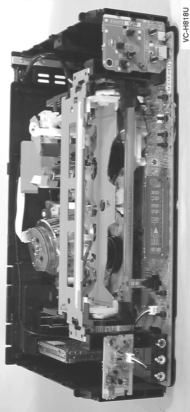
Click to zoom
Application Details
- Equipment Class
- HID - Part 15 TV Interface Device
- Date of Grant
- Feb 02, 2000
- Application Purpose
- Original Equipment
- Date of Application
- Dec 16, 1999
- Frequency Range
- 60.00000000 - 72.00000000
- Company
- Sharp Corporation
- Country
- Japan
Documents & Files
Document Text
Text extracted from the exhibit documents filed with the FCC. Open a document above to read the original.
Users Manual
1 Dimensions: 257 2 182 mm Printelligence (Malaysia) Sdn. Bhd.VC-H818U (01-10) VIDEO CASSETTE RECORDER OPERATION MANUAL Please read this operation manual carefully before using the VCR. General Information Setting Up Basic Operations Special Functions Helpful Hints Recording MODEL VC - H818U [IMPORTANT] / [IMPORTANTE] EZ SET UP (AUTO CHANNEL /CLOCK SET UP) EZ SET UP (PROGRAMACIÓN AUTOMÁTICA DE CANAL/PUESTA EN HORA DEL RELOJ) !Connect Antenna/Cable to VCR first. En primer lugar conecte la antena/el cable a la videograbadora. @Then, plug into AC Power Outlet. A continuación, enchúfelos al tomacorriente de CA. #Do not press the POWER button until completion of EZ SET UP. No pulse el botón de ALIMENTACIÓN (POWER) hasta haber terminado la EZ SET UP. $EZ SET UP complete. EZ SET UP completo. Detail: Please see page 16 Detalle: véase la página 16 Current time will be displayed and flashing. La hora actual aparecerá parpadeando en el visor. Printelligence (Malaysia) Sdn. Bhd. 2 VC-H818U (01-10) Dimensions: 257 2 182 mm This video cassette recorder (VCR) uses “ONLY” cassette tapes, NTSC video signals (standard in US), and 120 V AC, 60 Hz (standard US household current). For future reference, record the model and serial number (located on the rear of the VCR) in the space provided. Model No.: ————————— Serial No.: ————————— WARNING:TO REDUCE THE RISK OF FIRE OR ELECTRIC SHOCK, DO NOT EXPOSE THIS APPLIANCE TO RAIN OR MOISTURE. RISK OF ELECTRIC SHOCK DO NOT OPEN CAUTION This symbol warns the user of uninsulated voltage within the unit that can cause dangerous electric shocks. “WARNING—FCC Regulations state that any unauthorized changes or modifications to this equipment not expressly approved by the manufacturer could void the user’s authority to operate this equipment.” Note to CATV system installer: This reminder is provided to call the CATV system installer’s attention to Article 820-40 of the National Electrical Code that provides guidelines for proper grounding and, in particular, specifies that the cable ground shall be connected to the grounding system of the building, as close to the point of cable entry as practical. CAUTION: TO REDUCE THE RISK OF ELECTRIC SHOCK, DO NOT REMOVE COVER. NO USER- SERVICEABLE PARTS INSIDE. REFER SERVICING TO QUALIFIED SERVICE PERSONNEL. This symbol alerts the user that there are important operating and maintenance instructions in the literature accompanying this unit. As an ENERGY STAR ® Partner, SHARP has determined that this product meets the ENERGY STAR ® guidelines for energy efficiency. ENERGY STAR is a U.S. registered mark. WHAT IS ENERGY STAR ® TVs and VCRs use energy both when they are on and when they are off. Americans spend more than $1 billion a year on energy consumed by TVs and VCRs when they are not in use. The new ENERGY STAR ® models will reduce that energy "leakage" by up to 75 percent. Ultimately, this will mean more than $500 million a year in energy savings for consumers. The energy savings will help reduce the burning of fossil fuels and the related carbon dioxide pollution that contributes to global warming. If every American family replaced their TVs and VCRs with ENERGY STAR ® models, it would reduce carbon dioxide emissions by five million tons every year -- equivalent to eliminating the pollution from more than one million cars. By using ENERGY STAR ® products, you will save money on your electric bills and use less energy. That makes good economic sense and its good for our environment. WARNING OF DEW FORMATION Whenever your VCR is moved from a cold to a warm environment, it is important that you plug the unit in, turn the power on and allow it to sit for about 2 hours before attempting to play a tape. This period will allow any dew formation to evaporate. Failure to do so may result in tape and/or video head damage. After the 2 hour evaporation period, you may witness a “snowy” picture for the first few minutes of VCR operation. This picture noise will disappear shortly thereafter. WARNING—Keep your VCR away from electrical and magnetic appliances which could impair performance. Be sure to position your VCR away from your TV or video monitor by at least 8(. 3 Dimensions: 257 2 182 mm Printelligence (Malaysia) Sdn. Bhd.VC-H818U (01-10) IMPORTANT SAFEGUARDS AND PRECAUTIONS CAUTION READ THE SAFETY AND OPERATING INSTRUCTIONS before operating your VCR. FOLLOW INSTRUCTIONS AND HEED ALL WARNINGS on your VCR and in this manual. INSTALLATION 1. Operate only from a power source indicated on your VCR or in this manual. If you are unsure of your power supply, ask your local power company. 2. As a safety feature, your VCR is equipped with either a 2-wire polarized plug (one plug blade bigger than the other) or a 3-wire grounded plug (a third pin for grounding). The 2-wire polarized plug will fit only one way into the power outlet. The 3-wire grounded plug will fit only into a grounding-type power outlet. If the plug does not fit, ask your electrician to replace your obsolete outlet. Do not modify the plug. To do so will void the safety feature. 3. Protect and route power cords so they will not be stepped on or pinched by anything placed on or against them. Be especially careful at plug-ins, convenience receptacles, or cord exit points from the VCR. Frayed power cords or damaged plugs are hazardous. Have them replaced by a qualified service technician. Overloaded wall outlets and extension cords may cause fire or electrical shock hazards. 4. Do not cover or block ventilation holes in the VCR cabinet. Doing so may damage the VCR or cassette, or cause fire. Do not place your VCR on a soft surface which could block ventilation holes on the bottom. Avoid enclosed installations such as bookshelves or racks unless ventilation is adequate. 5. Avoid excessive humidity, sudden temperature changes, or temperature extremes. Dew may form inside your VCR or on the cassette. 6. To avoid costly damage or injury, place your VCR flat on a solid, stable surface free…
Text truncated - open the document above for the full version.
Cover Letter(s)
PST-9394 January 14, 2000 Federal Communications Commission 2025 M Street NW Washington, DC 20554 Attention: Mr. Joe Dichoso Subject:New exhibits for FCC ID APYTCG039, EA96282 Dear Mr. Dichoso, Attached are NEW exhibits that were left out of our original subject application that were requested by you in your e-mail dated 1-12-2000. Attachments: • Photo of transmitter PWB (component & solder side) • Location of transmitter PWB If you have any questions, please don’t hesitate to contact me. Sincerely, Tracey Pruitt Product Safety Engineer Product Safety Department (201) 529-9688 (201) 529-9642 Fax e-mail: [email protected]
Internal Photos
Locator PWB (Component Side) Locator PWB (Solder Side)
Contact Information
Applicant
Taihei Ohtsuka(Deputy Division Manager, ESG & Q promotion unit)
Technical Contact
Sharp ElectronicsTracey Pruitt
[email protected]201-529-9688
Sharp Plaza · Mahwah, New Jersey · United States
Test Firm
Japan Quality Assurance Org.Tetsuo Kato
Technical Specifications
| # | Rule Parts | Frequency Range | Power Output |
|---|---|---|---|
| 1 | 15B | 60 MHz - 72 MHz | - |
Other Applications from Sharp Corporation
APYHRO00344
Sep 10, 2026Smart phone
Equipment Class
NII - Unlicensed National Information Infrastructure TXAPYHRO00343
Aug 17, 2026Smartphone
Equipment Class
DTS - Digital Transmission SystemAPYHRO00342
Jul 29, 2026Smart phone
Equipment Class
DXX - Part 15 Low Power Communication Device TransmitterAPYHRO00341
May 28, 2026Smart phone
Equipment Class
DTS - Digital Transmission SystemAPYHRO00340
Dec 01, 2025BT remote control
Equipment Class
DTS - Digital Transmission System