AQO013Bluetooth Vehicle Key
Pektron Group Ltd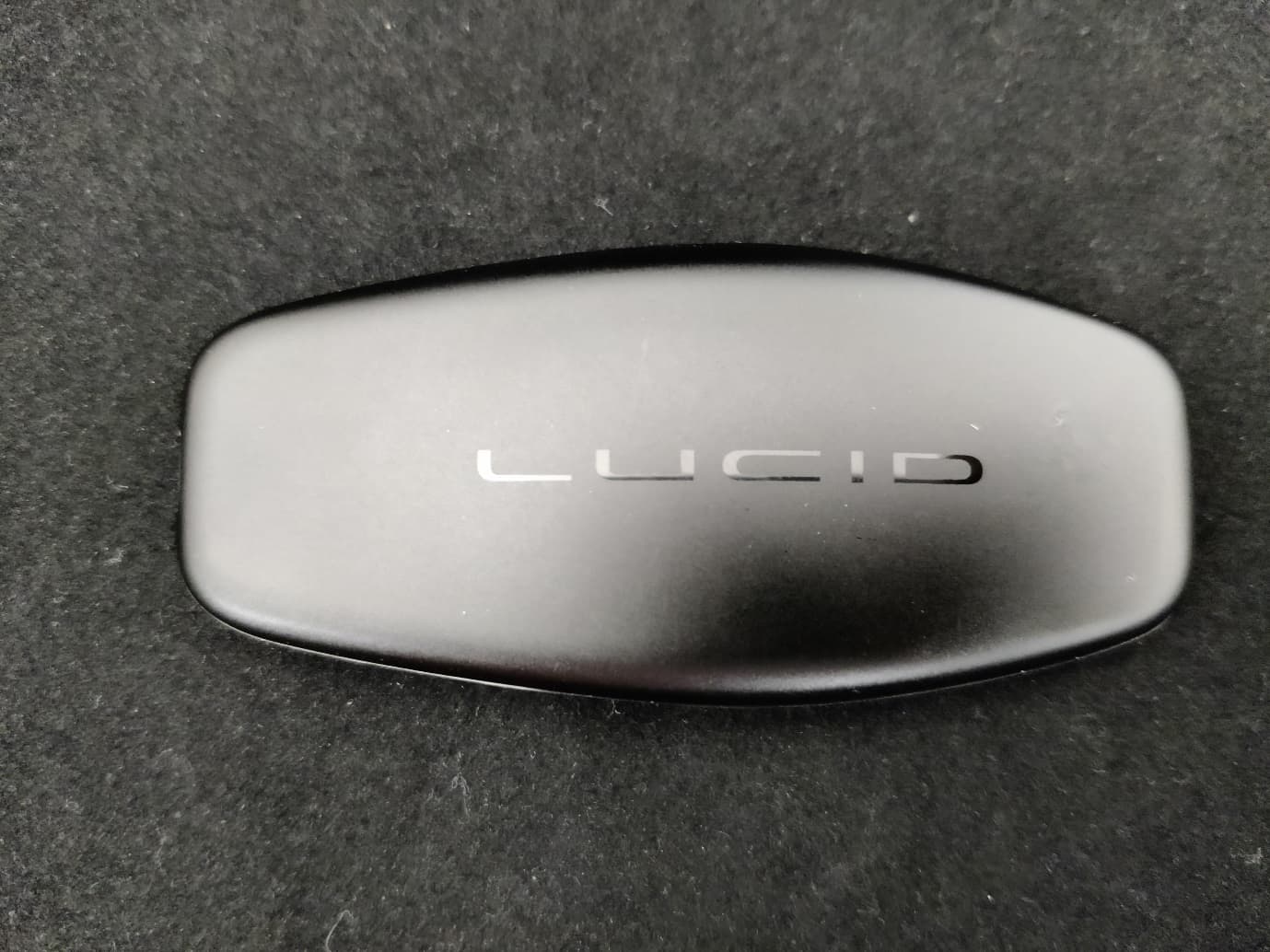
Click to zoom
Application Details
- Equipment Class
- DTS - Digital Transmission System
- Date of Grant
- May 18, 2021
- Application Purpose
- Original Equipment
- Date of Application
- May 18, 2021
- Equipment Note
- Bluetooth Vehicle Key
- Frequency Range
- 2402.00000000 - 2480.00000000
- Company
- Pektron Group Ltd
- Country
- United Kingdom
Documents & Files
Document Text
Text extracted from the exhibit documents filed with the FCC. Open a document above to read the original.
Users Manual
15 OPENING & CLOSING Keyless Entry System OPENING & CLOSINGKeyless Entry System Key Fob and NFC Card Your vehicle is delivered with two keyless entry system sets, each containing a key fob, lanyard, and Near-Field Communication (NFC) card. Using the NFC Card The NFC card is used within close range of the vehicle only, and is ideal for use as a backup entry device when needed. You might use or lend out the NFC card when: •Using a valet parking service •Leaving your vehicle to be serviced or repaired at a Lucid Service Center •Experiencing key fob issues (e.g. misplaced or low battery) Hold the NFC card within 2 in (5 cm) of the sensor on the left B pillar to lock or unlock the doors. Using the Key Fob WARNING: The keyless entry system uses low-frequency radio transmissions that might interfere with implanted medical devices. To avoid any possibility of interference, keep such medical devices away from any transmitters. WARNING: To avoid accidental operation of the vehicle's systems by other occupants, do not leave a key fob in an unattended vehicle. CAUTION: To ensure your vehicle is left in a secure state, remove all key fobs from the vehicle before leaving it unattended. Key fob range The key fob communicates with receivers in the vehicle via Bluetooth® Low Energy and low-frequency radio communication. While it is not necessary to point your key fob at the vehicle, it must be within operating range to work. Note: The key fob operating range can vary, depending upon environmental factors. Other nearby radio transmitters (e.g. amateur or CB radios, radio or television stations, airports) may interfere with communications between the key fob and the vehicle. Therefore, the ranges listed in this manual are approximate. In cases of interference, it may be necessary to move closer to the vehicle than usual in order to operate the key fob. 16 OPENING & CLOSING Keyless Entry System The key fob can be operated manually once it is detected within zone B or closer. Upon entering zone D while carrying a key fob, all doors automatically unlock and present their handles. When leaving your vehicle while carrying a key fob, all doors automatically lock and any presented door handles retract upon entering zone B. Key fob operation Upon entering zone B or closer, the key fob should be within range of the vehicle. Once within range, the key fob operates as follows: •Press once to lock all doors and the trunk. •Press twice to unlock all doors and the trunk. •Press and hold within zone D of the front or rear trunk to unlock and open. Key fob troubleshooting If the key fob does not respond when pressed: •Try operating the key fob as closely to your vehicle as possible. Other radio equipment operating on a similar frequency may interfere with the signals from your key fob. •The key fob battery may need to be replaced. See Replacing the Key Fob Battery, page 17. If you are still unable to unlock your vehicle with the key fob, use the NFC (Near-Field Communication) card. See Using the NFC Card , page 15. Contact a Lucid Service Center if the problem persists. ZoneRange A> 82 ft (25 m) = Out of range B82 ft (25 m) - 26 ft (8 m) C26 ft (8 m) - 6.5 ft (2 m) D<6.5 ft (<2 m) EInside vehicle 17 OPENING & CLOSING Keyless Entry System Replacing the Key Fob Battery WARNING: The key fobs supplied with your vehicle contain a coin/button type battery. The batteries contain toxic and corrosive substances. If a battery is swallowed it can cause serious internal burns and may even lead to death. •Keep new and used batteries out of the reach of children. •If you think batteries may have been swallowed or placed inside any part of the body, seek immediate medical help. WARNING: If the cover for the key fob will not close securely, stop using the key fob and keep it out of the reach of children. Contact a Lucid Service Center for a replacement key fob. WARNING: Risk of explosion if an incorrect battery is installed. Only install a battery which is identical to the battery specified. The key fob battery is type CR2032 and lasts for about 1 year, depending upon how often it is used. If the vehicle detects that the key fob battery is low, an alert will display on the Instrument Cluster. Note: To avoid complications with the vehicle systems, it is important to replace a low key fob battery as soon as possible. To replace the key fob battery: 1. Remove the battery cover. 2. Remove the old battery. 3. Avoid touching the flat surfaces of the new battery if possible, as finger marks can reduce battery life. Wipe the battery clean before installation. Fit the battery with the “+” side facing upwards. 4. Replace the battery cover. ENVIRONMENTAL: Used batteries must be disposed of correctly, as they contain harmful substances. Refer to local regulations. 18 OPENING & CLOSING Keyless Entry System Attaching a Lanyard A small lanyard is supplied with your key fob. To attach a lanyard: 1. Thread the loop of the lanyard through the small opening at the base of the key fob. 2. Thread the strap through the loop. 3. Pull the strap through the loop until it is tight. Caring for the Key Fob CAUTION: To protect the electronic circuitry inside, do not expose the key fob to: •Impacts •Liquids •High temperatures (including prolonged sunlight exposure) •Waxes, solvents, or abrasive cleaners Replacement Key Fobs If you lose a key fob, contact a Lucid Service Center to obtain a replacement. If ordering a new key fob, all available key fobs and NFC (Near-Field Communication) cards for the vehicle must be brought to the Lucid Service Center in order to reprogram the system. Type Approval US This device complies with Part 15 of the FCC Rules. Operation is subject to the following two conditions: 1. This device may not cause harmful interference, and 2. This device must accept any interference received, including interference that may cause undesired operation. This equipment complies with FCC radiation exposure limits set forth for an uncontrolled environment…
Text truncated - open the document above for the full version.
RF Exposure Info
18 RF Exposure KDB 447498 Section 4.3 General SAR test reduction and exclusion guidance For Standalone SAR exclusion consideration, when SAR Exclusion Threshold requirement in KDB 447498 is satisfied, standalone SAR evaluation for general population exposure conditions by measurement or numerical simulation is not required. The SAR Test Exclusion Threshold for frequencies in the range 100 MHz to 6 GHz, and for test separation distance of ≤ 50 mm, is determined as follows. SAR Exclusion Threshold (SARET) = (NT x TSD A ) / √ f GHz Where, NT = Numeric Threshold (3.0 for 1-g SAR and 7.5 for 10-g SAR) TSD A = Minimum Test separation distance or 50 mm (whichever is lower) f GHz = Transmit frequency in GHz Results: Frequency (MHz) Maximum Conducted Output Power (mW) SAR Exclusion Threshold at a distance of 5 mm (mW) SAR Evaluation 2402 0.7889.7Not Required 2440 0.8299.6Not Required 2480 0.8229.5Not Required T herefore standalone SAR evaluation for general population exposure conditions by measurement or numerical simulation is not required.
Test Report
RF915 7.0 Report on the Radio Testing For Pektron Group Limited on BTLE Keyfob Report no. TRA-051982-47-00B 18 May 2021 RF915 7.0 REPORT ON THE RADIO TESTING OF A Pektron Group Limited BTLE Keyfob WITH RESPECT TO SPECIFICATION FCC 47CFR 15.247 TEST DATE: 2021-02-22 to 2021-02-24 Written by: Steven Garwell Radio Test Engineer Approved by: Daniel Winstanley Senior - Radio Test Engineer Date: 18 May 2021 Disclaimers: [1] THIS DOCUMENT MAY BE REPRODUCED ONLY IN ITS ENTIRETY AND WITHOUT CHANGE [2] THE RESULTS CONTAINED IN THIS DOCUMENT RELATE ONLY TO THE ITEM(S) TESTED Report Number: TRA-051982-47-00B Issue: B Report Number: TRA-051982-47-00B RF915 7.0 Page 3 of 41 1 Revision Record Issue Number Issue Date Revision History A 2021-04-19 Original B 2021-05-18 Added antenna gain, amended FCC ID Report Number: TRA-051982-47-00B RF915 7.0 Page 4 of 41 2 Summary TEST REPORT NUMBER: TRA-051982-47-00B WORKS ORDER NUMBER: TRA-051982-02 PURPOSE OF TEST: USA: Testing of radio frequency equipment per the relevant authorization procedure of chapter 47 of CFR (code of federal regulations) Part 2, subpart J. TEST SPECIFICATION: FCC 47CFR 15.247 FCC ID: AQO013 EQUIPMENT UNDER TEST (EUT: BTLE Keyfob EUT SERIAL NUMBER: ` AB10000108 (Radiated) AB10000109 (Conducted) MANUFACTURER/AGENT: Pektron Group Limited ADDRESS: Alfreton Road Derby Derbyshire DE21 4AP United Kingdom CLIENT CONTACT: Richard Jones 01332832424 ext 382 [email protected] ORDER NUMBER: PROJ-00000632 TEST DATE: 2021-02-22 to 2021-02-24 TESTED BY: Steven Garwell, Michael Else Element Report Number: TRA-051982-47-00B RF915 7.0 Page 5 of 41 2.1 Test Summary Test Method and Description Requirement Clause Applicable to this equipment Result / Note 47CFR15 Radiated spurious emissions (restricted bands of operation and cabinet radiation) 15.205 Pass AC power line conducted emissions 15.207 Note 1 Occupied bandwidth 15.247(a)(2) Pass Conducted carrier power Peak 15.247(b)(3) Pass Max. Conducted / radiated RF power out-of- band 15.247(d) Pass Power spectral density, conducted 15.247(e) Pass Calculation of duty correction 15.35(c) - Note 1: Not applicable, not connected to the mains. Notes: The results contained in this report relate only to the items tested, in the condition at time of test, and were obtained in the period between the date of initial receipt of samples and the date of issue of the report. The apparatus was set up and exercised using the configurations, modes of operation and arrangements defined in this report only. Any modifications made are identified in Section 8 of this report. Particular operating modes, apparatus monitoring methods and performance criteria required by the standards tested to have been performed except where identified in Section 5.2 of this test report (Deviations from Test Standards). Report Number: TRA-051982-47-00B RF915 7.0 Page 6 of 41 3 Contents 1 Revision Record ................................................................................................................................ 3 2 Summary ........................................................................................................................................... 4 2.1 Test Summary ........................................................................................................................... 5 3 Contents ............................................................................................................................................ 6 4 Introduction ....................................................................................................................................... 8 5 Test Specifications ............................................................................................................................ 9 5.1 Normative References .............................................................................................................. 9 5.2 Deviations from Test Standards ................................................................................................ 9 6 Glossary of Terms ........................................................................................................................... 10 7 Equipment Under Test .................................................................................................................... 11 7.1 EUT Identification .................................................................................................................... 11 7.2 System Equipment .................................................................................................................. 11 7.3 EUT Mode of Operation .......................................................................................................... 11 7.3.1 Transmission ................................................................................................................... 11 7.4 EUT Radio Parameters ........................................................................................................... 11 7.5 EUT Description ...................................................................................................................... 11 8 Modifications ................................................................................................................................... 12 9 EUT Test Setup .............................................................................................................................. 13 9.1 Block Diagram ......................................................................................................................... 13 9.2 Measurement software ............................................................................................................ 14 10 General Technical Parameters.................................................................................................... 15 10.1 Normal Conditions .......................................................................................…
Text truncated - open the document above for the full version.
Test Setup Photos
General Set-up Photograph The following photograph shows basic EUT set-up:
Contact Information
Applicant
Nicholas John Thornley Wren(Mr)
Test Firm
Element Materials Technology Warwick LtdNeil Roche
Technical Specifications
| # | Rule Parts | Frequency Range | Power Output |
|---|---|---|---|
| 1 | 15C | 2.40 GHz - 2.48 GHz | 800.00 µW |
Other Applications from Pektron Group Ltd
AQO012
May 18, 2021Bluetooth Security Node
Equipment Class
DTS - Digital Transmission System
AQO011
May 18, 2021Bluetooth Security Node with NFC
Equipment Class
DXX - Part 15 Low Power Communication Device Transmitter
AQO002
Jun 21, 2012Key
Equipment Class
DSR - Part 15 Remote Control/Security Device Transceiver