AUIGMRS1100B22 Channel 2 Ways GMRS (with 467MHz FRS Channels)
Musical Electronics Ltd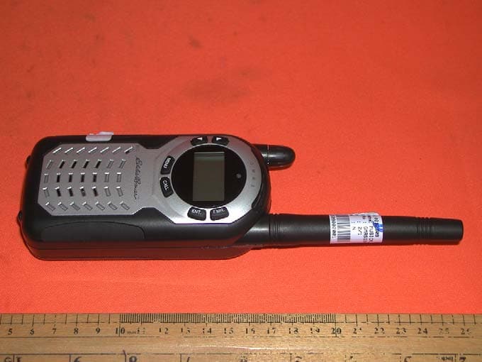
Click to zoom
Application Details
- Equipment Class
- FRF - Part 95 Family Radio Face Held Transmitter
- Date of Grant
- Feb 27, 2003
- Application Purpose
- Original Equipment
- Date of Application
- Oct 07, 2002
- Equipment Note
- 22 Channel 2 Ways GMRS (with 467MHz FRS Channels)
- Frequency Range
- 467.56250000 - 467.71250000
- Company
- Musical Electronics Ltd
- Country
- Hong Kong
Documents & Files
Document Text
Text extracted from the exhibit documents filed with the FCC. Open a document above to read the original.
External Photos
Test Setup FCCID : AUIGMRS1100B External Photo -front External Photo - rear
Internal Photos
Test Setup FCCID : AUIGMRS1100B Internal Photo - 1 Internal Photo - 2 Test Setup FCCID : AUIGMRS1100B Internal Photo – 3 Internal Photo – 4 Test Setup FCCID : AUIGMRS1100B Internal Photo – 5 Internal Photo - 6 Test Setup FCCID : AUIGMRS1100B Internal Photo – 7 Internal Photo - 8 Test Setup FCCID : AUIGMRS1100B Internal Photo - 9
RF Exposure Info
TEST REPORT Your Ref:Date: 20 Sept 2002 Our Ref: 56S020339/01_CORR01 Page: 1 of 21 DID: (65) 68851464 Fax: (65) 67741459 LA-2001-0212-A LA-2001-0213-F LA-2001-0214-E LA-2001-0215-B LA-2001-0216-G LA-2001-0217-G The results reported herein have been performed in accordance with the laboratory’s terms of accreditation under the Singapore Accreditation Council - Singapore Laboratory Accreditation Scheme PSB Corporation • Testing Group • 1 Science Park Drive Singapore 118221 • Fax 6775 9725 • Email [email protected] • Website www.psbcorp.com Your product quality and safety mark NOTE: This Report is issued subject to the “Terms and Conditions Governing Technical Services” set out in the “Request for Technical Services” form. The terms and conditions governing the issue of this report are set out overleaf. FORMAL REPORT ON TESTING IN ACCORDANCE WITH SAR (SPECIFIC ABSORPTION RATE) REQUIREMENTS Supplement C (Edition 01-01) to FCC OET Bulletin 65 (Edition 97-01) OF 22 Channel 2 ways GMRS (with 467MHz FRS channels) [ Models: Musical GMRS1100B and Eddie Bauer EBC-700 ] TEST FACILITY Telecoms & EMC, Testing Group, PSB Corporation 1 Science Park Drive, Singapore 118221 PREPARED FOR Mr. Cheuk Ching Musical Electronics Limited 5/F, Wider Industrial Bldg, 58 Tsun Yip St, Kwun Tong, Kowloon, Hong Kong Tel: (852) 2341 9281Fax: (852) 2341 9964 JOB NUMBER 56S020339 TEST PERIOD 13 Sept 2002 – 19 Sept 2002 PREPARED BYAPPROVED BY ____________________ Gary Ng Ah Chye Technical Executive ____________________ Benjamin Foo Assistant Vice President April 2002Page 2 of 21 This Report is issued under the following conditions: 1. Results of the testing/calibration in the form of a report will be issued immediately after the service has been completed or terminated. 2. Unless otherwise requested, a report shall contain only technical results. Analysis and interpretation of the results and professional opinion and recommendations expressed thereupon, if required, shall be clearly indicated and additional fee paid for, by the Client. 3. This report applies to the sample of the specific product/equipment given at the time of its testing/calibration. The results are not used to indicate or imply that they are applicable to other similar items. In addition, such results must not be used to indicate or imply that PSB Corporation approves, recommends or endorses the manufacturer, supplier or user of such product/equipment, or that PSB Corporation in any way “guarantees” the later performance of the product/equipment. 4. The sample/s mentioned in this report is/are submitted/supplied/manufactured by the Client, PSB Corporation therefore assumes no responsibility for the accuracy of information on the brand name, model number, origin of manufacture, consignment or any information supplied. 5. Additional copies of the report are available to the Client at an additional fee. No third party can obtain a copy of this report through PSB Corporation, unless the Client has authorised PSB Corporation in writing to do so. 6. PSB Corporation may at its sole discretion add to or amend the conditions of the report at the time of issue of the report and such report and such additions or amendments shall be binding on the Client. 7. All copyright in the report shall remain with PSB Corporation and the Client shall, upon payment of PSB Corporation’s fees for the carrying out of the tests/calibrations, be granted a license to use or publish the report to the third parties subject to the terms and conditions herein, provided always that PSB Corporation may at its absolute discretion be entitled to impose such conditions on the license as it sees fit. 8. Nothing in this report shall be interpreted to mean that PSB Corporation has verified or ascertained any endorsement or marks from any other testing authority or bodies that may be found on that sample. 9. This report shall not be reproduced wholly or in parts and no reference shall be made by the Client to PSB Corporation or to the report or results furnished by PSB Corporation in any advertisements or sales promotion. 56S020339/01_CORR01Musical Electronics LimitedPage 3 of 21 22 Channel 2 ways GMRS (with 467MHz FRS channels) [ Models: Musical GMRS1100B and Eddie Bauer EBC-700 ] TABLE OF CONTENTS TEST SUMMARY PRODUCT DESCRIPTION TEST RESULTS ANNEX A-TEST INSTRUMENTATION & GENERAL PROCEDURES ANNEX B-EUT PHOTOGRAPHS / DIAGRAMS Test Setup EUT Photographs ANNEX C-TISSUE SIMULANT DATA SHEETS ANNEX D-SAR VALIDATION RESULTS ANNEX E-REFERENCES 56S020339/01_CORR01Musical Electronics LimitedPage 4 of 21 22 Channel 2 ways GMRS (with 467MHz FRS channels) [ Models: Musical GMRS1100B and Eddie Bauer EBC-700 ] TEST SUMMARY The product was tested in accordance with the following standards. Test Results Summary Test StandardsDescription Pass / Fail SAR Measurement (450MHz Head Tissue) Pass > • Supplement C (Edition 01-01) to FCC OET Bulletin 65 (Edition 97-01) • ANSI/IEEE Standard C95.1-1993 SAR Measurement (450MHz Body Tissue) Pass > NOTE : 1. The worst-case SAR value was found to be 1.200W/kg which is lower than the maximum limit of 1.60 W/kg, over 1g of tissue . >Based on spatial peak uncontrolled exposure / general population level: Head: 1.60 W/kg, over 1g of tissue. Body: 1.60 W/kg, over 1g of tissue. Customer’s Declaration The client declared that the EUT Model: GMRS1100B [i.e. trade name: Musical (original basic model)] and Model: EBC-700 [i.e. trade name: Eddie Bauer (FCC multiple listing additional model)] are identical in electrical, mechanical and physical design, including software/firmware except brand name, model number and some cosmetics. Modifications No modifications were made. 56S020339/01_CORR01Musical Electronics LimitedPage 5 of 21 22 Channel 2 ways GMRS (with 467MHz FRS channels) [ Models: Musical GMRS1100B and Eddie Bauer EBC-700 ] DEVICE DESCRIPTION DEVICE DESCRIPTION DescriptionThe Equipment Under Test (EUT) is a 22 Channel 2 ways GMRS (with 467MHz FRS channels). Device CategoryPorta…
Text truncated - open the document above for the full version.
RF Exposure Info
Page 1 Re: FCC ID AUIGMRS1100B Applicant: Musical Electronics Ltd Correspondence Reference Number: 24419 731 Confirmation Number: EA542660 Date of Original E-Mail: 11/22/2002 Subject: SAR In regards to your recent application referenced above we kindly request that you provide the following additional information. With reference to the FCC E-mail dated 22 Nov 02, following are the responses (in blue). 1) New SAR values and data as follows. The FCC believes the SAR tests performed contain factors that significantly increase measurement uncertainty. Primarily, the large power droop in the device under test produces a dynamic SAR distribution. The SAR measurement system used appears to assume a constant distribution. We suggest that the measured SAR values be scaled up by the drift to establish a conservative SAR value. To determine the extent of the problem and to optimize SAR measurement please provide support data including power vs time plot, and time length of SAR measurements. Response: The time length of SAR measurement, Power vs Time plot are provided for EUT using battery only, 6VDC only and battery + 6VDC. The details are on Annex A.1 Than to validate if the scaled SAR values are conservative please perform two additional tests if possible to reduce the effect of power droop. 1) a SAR test using an external power supply to supplement the batteries. Please use shielding and ferrite current dampeners on any wires used. Response: SAR test were carried out using external power supply to supplement the batteries. Shielding and ferrite current dampeners are used on the wires of the external power supply. Page 2 2) A test starting at a time when the power is most stable (based on power vs time data), the SAR value should than be scaled up to full power. Or alternatively, perform shorten/focused scans over the hotspot. Tests in the worst case configuration is considered sufficient. Response: From the Power Vs Time Plot for Energizer Battery + 6VDC, it can be observed that the power droop after the first 10 minutes is less significant. That is the power is most stable after 10 minutes of continuous transmission. SAR measurement was carried out in the worst case configuration (Belt Clip Body Worn at Channel 4) after the EUT (using Energizer Battery + 6VDC) has transmitted for 10 minutes. The SAR values obtained are scaled up to the full power (or initial power). Please refer to Annex A.1.b for results 2) Clarification on the battery type used for testing. Rechargeable? If commercial AA batteries can be used please provide SAR data with several typical manufacturer batteries. Please address the power droop concern mentioned above for each. Data at the worst case SAR configuration is considered sufficient. Response: Alkaline AA non-rechargeable batteries are used for the SAR measurement. 3 brands of commercial AA batteries are investigated. The 3 brands are Energizer, Panasonic and GP Ultra. For data for the worst case SAR configuration, please refer to Annex A.2 3) Liquid depths during testing. If available please provide photographs, and Z-axis scan SAR data for the highest SAR test points. Response: The liquid depth during testing is 15±0.5 cm. Please refer to Annex A.3.a for photograph. The Z-axis SAR scan for the highest SAR test point is also provide (See Annex A.3.b) 4) Description of the probe used for testing including a physical description, calibration information and measurement errors. Please include manufacturer calibration certificates. Per Supplement C Appendix B part II 2. Response: The description of the probe used for testing is provided in Annex A.4. Manufacturer calibration certificates are also attached. Page 3 5) A description of the measurement system and how the SAR measurements are actually performed once setup: include coarse scan, determination of peak SAR location, scans to measure points in 1 gram volume, and procedure to determine SAR value from the measurement points. Per Supplement C Appendix B part II 7 and 8. Response: A description of the measurement system and how the SAR measurements are actually performed once setup are provided in Annex A.5 6) Manufacturer system validation data. Please also provide forward power used. Response: The manufacturer system validation data is provided in Annex A.6. The forward power used by manufacturer is 389mW whereas the forward power used by test lab was 250mW. A table with a summary of the normalized SAR values to 1W is also provided. 7) Justification of the SAR results using a 4 mm thick phantom. Supplement C recommends a 2 mm thick phantom. Please provide an analysis of the expected effect on SAR. Please make efforts to obtain a 2 mm thick phantom for future measurements. Response: The test lab is in the process of acquiring a 2mm thick phantom for future measurement. An analysis of the effect of SAR shows that the 4mm phantom could result in a SAR value that is about 5% lower than that of a 2mm SAM phantom. Please see Annex A.7 for details Page 4 ANNEX A.1 a) Time Length of Measurement = 16 min 28 sec b) Power Vs Time Plot Result Overview Energizer Battery only 6VDC only Energizer Battery + 6VDC Remarks Initial Power / W 1.52 1.82 1.83 Power at 10min / W 1.01 1.46 1.47 Start SAR Test Power at 20min / W 0.912 1.42 1.42 Power at 30min / W 0.857 1.40 1.41 End SAR Test i) Using Energizer Battery only, POWER MEASUREMENT USING ENERGIZER BATTERY 0 0.2 0.4 0.6 0.8 1 1.2 1.4 1.6 1.8 0.0010.0020.0030.0040.00 TIME (MIN) POWER (WATT) Page 5 ii) Using 6VDC only POWER MEASUREMENT USING 6VDC 0 0.5 1 1.5 2 0.0010.0020.0030.0040.00 TIME (MIN) POWER (WATT) iii) Using Energizer Battery + 6VDC, POWER MEASUREMENT USING ENERGIZER BATTERY + 6 VDC 0 0.5 1 1.5 2 0.0010.0020.0030.0040.00 TIME (MIN) POWER (WATT) Page 6 From the Power Vs Time Plot for Energizer Battery + 6VDC, it can be observed that the power droop after the first 10 minutes is less significant. That is the power is most stable after 10 minutes of continuous transmission. SAR …
Text truncated - open the document above for the full version.
Test Report
Modulation Frequency Response 0.00 0.50 1.00 1.50 2.00 20070012001700220027003200370042004700 Modulation Frequency (Hz) Frequency Deviation (kHz) Modulation Frequency Response 0.00 1.00 2.00 3.00 20070012001700220027003200370042004700 Modulation Frequency (Hz) Modulation Index (%)
Test Report
Modulation Limiting Characteristic 0.00 0.50 1.00 1.50 2.00 2.50 3.00 475767778797107117127137 Modulation Input (dBSPL) Frequency Deviation (kHz) 500Hz 1000Hz 2500Hz 3125Hz
Test Report
• The test results reported in this report shall refer only to the sample actually tested and shall not refer or be deemed a refer to bulk from which such a sample may be said to have been obtained. • This report shall not be reproduced except in full without prior authorization from Intertek Testing Services Hong Kong Limited • For Terms And Conditions of the services, it can be provided upon request. • The evaluation data of the report will be kept for 3 years from the date of issuance. Intertek Testing Services Hong Kong Ltd. 2/F., Garment Centre, 576 Castle Peak Road, Kowloon, Hong Kong. Tel: (852) 2173 8888 Fax: (852) 2785 5487 Musical Electronics Limited Application For Certification (FCC ID: AUIGMRS1100B) October 5, 2002 WO# 0212509 WL/SL October 5, 2002 INTERTEK TESTING SERVICES FCC ID: AUIGMRS1100B i SUMMARY OF CONTENTS LIST OF EXHIBITS EXHIBIT 1: General Description EXHIBIT 2: System Test Configuration EXHIBIT 3: RF Power Output EXHIBIT 4: Modulation Characteristics EXHIBIT 5: Occupied Bandwidth EXHIBIT 6: Spurious Emission EXHIBIT 7: Frequency Stability EXHIBIT 8: Technical Specifications EXHIBIT 9: Product Labelling EXHIBIT 10: Photographs EXHIBIT 11: Instruction Manual EXHIBIT 12: Tune Up Procedure EXHIBIT 13: Part List EXHIBIT 14: Input Current EXHIBIT 15: RF Exposure Info INTERTEK TESTING SERVICES FCC ID: AUIGMRS1100B ii MEASUREMENT/TECHNICAL REPORT Application : Musical Electronics Limited Trade Name/Model No : Musical GMRS1100B Eddie Bauer EBC-700 Date : October 5, 2002 This report concerns (check one:)Original Grant X Class II Change Equipment Type: Family Radio Service Plus General Mobile Radio Service, FRS + GMRS Deferred grant requested per 47 CFR 0.457(d)(1)(ii)? Yes No X If yes, defer until: date Company Name agrees to notify the Commission by: date of the intended date of announcement of the product so that the grant can be issued on that date. Report prepared by: Wilson Loke Intertek Testing Services 2/F., Garment Centre, 576 Castle Peak Road, Kowloon, Hong Kong. Phone: 852-2173-8575 Fax: 852-2371-0521 INTERTEK TESTING SERVICES FCC ID: AUIGMRS1100B iii Table of Contents 1.0 General Description............................................................................................................2 1.1 Product Description........................................................................................................2 1.2 Related Submittal(s) Grants ..........................................................................................3 1.3 Test Methodology..........................................................................................................3 1.4 Test Facility ...................................................................................................................3 2.0 System Test Configuration.................................................................................................5 2.1 Justification ....................................................................................................................5 2.2 EUT Exercising Software ..............................................................................................6 2.3 Special Accessories .......................................................................................................6 2.4 Measurement Uncertainty .............................................................................................6 2.5 Equipment Modification ................................................................................................6 3.0 RF Output Power (Section 95.639(d))................................................................................8 4.0 Modulation Characteristics (Section 95.637(a))..............................................................12 4.1 Modulation Frequiency Response.................................................................................13 4.2 Modulation Limiting Characteristic...............................................................................15 4.3 Audio Low Pass Filter Response .................................................................................17 5.0 Occupied Bandwidth (Section 95.633(c)) ........................................................................19 6.0 Spurious Emission (Section 95.635(b)) ............................................................................21 6.1 Field Strength of Spurious Radiation ............................................................................22 7.0 Frequency Stability (Section 95.627)...............................................................................28 7.1 Frequency Tolerance.....................................................................................................29 7.2 Temperature Extreme Condition ...................................................................................31 7.3 Voltage Extreme Condition...........................................................................................34 8.0 Technical Specifications...................................................................................................37 9.0 Product Labelling.............................................................................................................41 10.0 Equipment Photographs.................................................................................................44 11.0 Instruction Manual.........................................................................................................46 12.0 Tune Up Procedure.........................................................................................................48 13.0 Part List...........................................................................................................................50 14.0 Input Current.................................................................................................................52 15.0 RF Exposure Info.................................................................…
Text truncated - open the document above for the full version.
Test Report
Audio Low Pass Filter Response -70.0 -60.0 -50.0 -40.0 -30.0 -20.0 -10.0 0.0 10.0 110100 Frequency (kHz) dB relative to 1 kHz LPF Response TIA/EIA-603
Test Setup Photos
Test Setup FCCID : AUIGMRS1100B Radiated -front Radiated - rear
Contact Information
Applicant
Richard Leung(VP - Innovation & Technology)
Technical Contact
Intertek Testing Services Hong Kong Ltd.Wilson Loke
[email protected](852) 21738575
2/F., Garment Centre, · Kowloon · Hong Kong
Non-Technical Contact
Intertek Testing Services Hong Kong Ltd.Wilson Loke
[email protected](852) 21738575
Test Firm
Intertek Testing Services Hong KongBilly Chow
Technical Specifications
| # | Rule Parts | Frequency Range | Power Output | Emission | Tolerance |
|---|---|---|---|---|---|
| 2 | 95B | 467.5625 MHz - 467.7125 MHz | 440.00 mW | 10K8F3E | 2.5 ppm |
Other Applications from Musical Electronics Ltd
AUIG860
Jul 07, 2024G-BOOM4, Bluetooth Wireless Boombox
Equipment Class
DSS - Part 15 Spread Spectrum TransmitterAUI100135464
Jan 21, 2024Cassette Boombox Black
Equipment Class
DSS - Part 15 Spread Spectrum Transmitter
AUIG850
Jan 24, 2021Bluetooth Wireless Boombox
Equipment Class
DXX - Part 15 Low Power Communication Device Transmitter
AUINSCBBTCD01-B
Apr 27, 2015CD Boombox with Bluetooth
Equipment Class
DTS - Digital Transmission System
AUIRX-DBT30
Jul 20, 2014Portable Stereo CD System
Equipment Class
DXX - Part 15 Low Power Communication Device Transmitter