AUSC6BC6 TURNTABLE
Modern Marketing Concepts, Inc.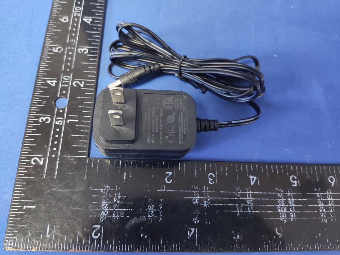
Click to zoom
Application Details
- Equipment Class
- DTS - Digital Transmission System
- Date of Grant
- Jul 21, 2020
- Application Purpose
- Original Equipment
- Date of Application
- Jul 20, 2020
- Equipment Note
- C6 TURNTABLE
- Frequency Range
- 2402.00000000 - 2480.00000000
- Country
- United States
Documents & Files
Document Text
Text extracted from the exhibit documents filed with the FCC. Open a document above to read the original.
Users Manual
C6B C6 Turntable Instruction Manual Questions, problems, missing parts? Before returning to the store, call Customer Service 8 a.m. – 6 p.m., EST, Monday – Friday 1-888-CROSLEY www.crosleyradio.com/support English 2 Safety Instructions Read and understand this entire manual before using this product. Keep these instructions for future reference. 1. Do not use this product near water. 2. This product should be operated only by the type of power source indicated on the marking label or in this instruction manual. 3. Do not defeat the safety purpose of the polarized plug. A polarized plug has two blades with one blade wider than the other. This plug will fit into the power outlet only one way. If you are unable to insert the plug fully into the outlet try reversing the plug. If the plug should still fail to fit, contact your electrician. 4. Protect the power cord from being walked on or pinched particularly at plugs, convenience receptacles, and the point where they exit from the product. 5. Do not overload wall outlets, extension cords, or integral convenience receptacles as this can result in a risk of fire or electric shock. 6. Never push objects of any kind into this product through openings as they may touch dangerous voltage points or short-out parts that could result in a fire or electric shock. Never spill liquid of any kind on the product. 7. Do not attempt to service this product yourself as opening or removing covers may expose you to dangerous voltage or other hazards. Refer all servicing to qualified service personnel. 8. Changes or modifications to this unit not expressly approved by the party responsible for compliance could void the user’s authority to operate the equipment. 9. Do not use attachments not recommended by the product manufacturer as they may cause hazards. 10. A product and cart combination should be moved with care. Quick stops, excessive force, and uneven surfaces may cause the product and cart combination to overturn. 11. Slots and openings in the cabinet are provided for ventilation and to ensure reliable operation of the product and to protect it from overheating. Do not block or cover these openings. 12. Unplug the product during lightning storm or when unused for long periods of time. Items in this package Before throwing away any packaging materials, please check thoroughly and make sure you find the following items that come along with this package: Turntable Turntable Lid Turntable Slip Mat Turntable Platter Tonearm Counterweight Cartridge Alignment Protractor Power Adaptor 45 RPM adapter RCA cable Please contact Crosley customer service if there is any accessory missing from the package. Retain the original packaging materials for exchange or return purposes. English 3 Specifications Crosley C6B Power DC power adaptor, DC output 12V 0.5A Power Consumption 5W Turntable Speed 33 1 / 3 , 45 RPM Speed Variance +0.8% Wow and Flutter +0.15% Signal to Noise 72dB Effective Tonearm Length 8.6” (218.5mm) Overhang 0.73” Weight 13.67 lbs Needle: Crosley NP-5 Frequency Response 20Hz – 20kHz Channel Balance <2.5 dB Channel Separation >18 dB Output Voltage 2.5 mV Recommended Load Resistance 47k Ω Amplifier connection MM – input Recommended Tracking Pressure3.5±0.5g Weight 0.18oz Note: Design and specifications are subject to change without notice. English 4 Product Description 1. Hinge 2. Drive Pulley 3. Drive Belt 4. Turntable Spindle 5. Turntable Hub 6. Turntable Platter 7. Tonearm Lift 8. Tonearm Counterweight 9. Downforce Scale Dial 10. Tonearm Lift Lever 11. Tonearm Rest 12. Tonearm 13. Headshell 14. Speed Selector 15. Ground Connector 16. RCA Jacks 17. Phone/Line Switch 18. Power Jack 19. Bluetooth Indicator 20. Power Switch English 5 Initial Setup Essential Setup 1. Place the unit on a flat and level surface. The selected location should be stable and free from vibration. 2. Install the turntable lid to the hinges. 3. Remove the tie-wrap that is holding the tonearm. 4. Install the turntable platter and drive belt accordingly 5. Place the slip mat on top of the turntable platter. 6. Slide Tonearm Counterweight onto tonearm and twist it lightly onto the rear shaft of the tonearm. 7. Adjust the counterweight to set proper stylus pressure. 8. Connect DC adaptor to the Power Jack of the unit. Note: Do not plug the DC power adaptor to power outlet before all the assembly is completed. Before turning the power on, make sure again all the connection settings are correct. Always turn off the power when connecting or disconnecting. Tonearm Counterweight Adjustment for Stylus Pressure 1. Remove the stylus protector from the cartridge and avoid touching the stylus tip during the adjustment. 2. Lift up the Tonearm from its rest and gently hold it. The tone arm is unbalanced at this point. 3. Carefully rotate the Counterweight towards the front of the turntable until the tonearm is horizontally balanced and hovers freely just above the platter without the stylus touching the platter surface. 4. Return the tonearm to the Tonearm Rest. 5. While holding the counterweight steady without any rotation, rotate carefully only the Downforce Scale Dial until the “0” on the scale lines up with the centerline marked along the top of the tonearm. 6. Rotate the counterweight including the downforce scale dial counter-clockwise (as seen from the front of the turntable) to adjust the pressure to the stylus manufacturer recommendations. Note: - Each mark on the scale represents 0.05g (gram). - The recommended pressure for the factory-installed cartridge is 3.5g. Note: The cartridge only goes up to 1.75g. You will need to make two full rotations to reach 3.5g. Turntable Platter and Belt Setup 1. Put the drive belt around the Turntable Hub, and then use the provided drive belt assembly tool to help pull the belt to fit around the slot of motor pulley. 2. Place the turntable platter through the turntable spindle. Stereo System Connection RCA Jacks • The RCA Jacks of this …
Text truncated - open the document above for the full version.
Cover Letter(s)
TOTEM ACOUSTIQUE INC. for Certification Service in USA Federal Communication Commission Equipment Authorization Division, Application Processing Branch 7435 Oakland Mills Road Columbia, MD 21046 <2020-07-17> TO WHOM IT MAY CONCERN Pursuant to Paragraphs §0.457 and 0.459 of the Commission’s Rules (47 C.F.R.) and Section §552(b)(4) of the Freedom of Information Act, we requests confidentiality for the following products: FCC ID Model name AUSC6B C6B-BK For the product stated above, we request that the following information be held confidential; Exhibits Long-Term Confidentiality Short-Term Confidentiality Short-Term Confidentiality Days External Photos Internal Photos Block Diagram Schematics Test Setup Photos User’s Manual Parts List Tune Up Operational Descriptions The long-term confidentiality exhibits contain our trade secrets and proprietary information that could be of benefit to our competitors. The short-term confidentiality on the basis of ensuring that business sensitive information remains confidential until the actual marketing of our new device. If you have any questions, please feel free to contact me at the address shown below. Sincerely, ------------------------------------ Name: Scott McWhorter/Director of Engineering Company: Modern Marketing Concepts, Inc. Address: 1220 E Oak, St. Louisville, Kentucky, United States 40204 Phone: +1-502-212-4291 Fax: +1-502-212-4291 E-Mail: [email protected]
Cover Letter(s)
Modern Marketing Concepts, Inc. 1220 E Oak, St. Louisville, Kentucky, United States 40204 Tel: +1-502-212-4291 Fax: +1-502-212-4291 Federal Communications Commission Authorization and Evaluation Division Equipment Authorization Branch 7435 Oakland Mills Road Columbia, MD 21046 2020/07/17 To whom it may concern: We, the undersigned, hereby authorize Eurofins Product Service GmbH to act on our behalf in all matters relati ng to applications for equipment authorization FCC ID: [AUSC6B] including the signing of all documents related to these matters. Any and all acts carried out by Eurofins Product Service GmbH on our behalf shall have the same effect as acts of our own. We also hereby certify that no party to this application is subject to a denial of benefits, including FCC benefits, pursuant to Section 5301 of the Anti-Drug Abuse Act of 1988, 21 U.S.C. 862. Sincerely, Name: Scott McWhorter/Director of Engineering Company: Modern Marketing Concepts, Inc. Address: 1220 E Oak, St. Louisville, Kentucky, United States 40204 Phone: +1-502-212-4291 Fax: +1-502-212-4291 E-Mail: [email protected]
Cover Letter(s)
FCC ID: AUSC6B Modern Marketing Concepts, Inc. Model Difference Model: C6B-BK, C6X-XXXX(“X-XXXX” can be replaced by letter from “A” to “Z”, number from “0” to “9” or blank) All models have same circuits diagram of Bluetooth module PCB, RF Chip constructionl; All models have same circuits diagram of Power ; Product's power amplifier board, control board and rated power are different. Sincerely, Name: Scott McWhorter/Director of Engineering Company: Modern Marketing Concepts, Inc. Address: 1220 E Oak, St. Louisville, Kentucky, United States 40204 Phone: +1-502-212-4291 Fax: +1-502-212-4291 E-Mail: [email protected]
External Photos
FCC ID: AUSC6B FCC ID: AUSC6B FCC ID: AUSC6B FCC ID: AUSC6B
ID Label/Location Info
FCC ID LOCATION
Internal Photos
FCC ID: AUSC6B BT ANT FCC ID: AUSC6B
RF Exposure Info
RF Exposure evaluation Exposure category: General population/uncontrolled environment EUT Type: Production Unit Device Type: Mobile Device Refer Standard: KDB 447498 D01 General RF Exposure Guidance v06 FCC Part 2 §2.1091 FCC ID: AUSC6B 1. Reference According to §1.1307(b)(1), systems operating under the provisions of this section shall be operated in a manner that ensures that the public is not exposed to radio frequency energy level in excess of the Commission’s guidelines. According to §1.1310 and §2.1091 RF exposure is calculated. KDB447498 D01: Mobile and Portable Devices RF Exposure Procedures and Equipment Authorization Policies 2. Limit Limits for Maximum Permissible Exposure (MPE)/Controlled Exposure Frequency Range(MHz) Electric Field Strength(V/m) Magnetic Field Strength(A/m) Power Density (mW/cm²) Averaging Time (minute) Limits for Occupational/Controlled Exposure 0.3 – 3.0 614 1.63 (100) * 6 3.0 – 30 1842/f 4.89/f (900/f 2 )* 6 30 – 300 61.4 0.163 1.0 6 300 – 1500 / / f/300 6 1500 – 100,000 / / 5 6 Limits for Maximum Permissible Exposure (MPE)/Uncontrolled Exposure Frequency Range(MHz) Electric Field Strength(V/m) Magnetic Field Strength(A/m) Power Density (mW/cm²) Averaging Time (minute) Limits for Occupational/Controlled Exposure 0.3 – 3.0 614 1.63 (100) * 30 3.0 – 30 824/f 2.19/f (180/f 2 )* 30 30 – 300 27.5 0.073 0.2 30 300 – 1500 / / f/1500 30 1500 – 100,000 / / 1.0 30 F=frequency in MHz *=Plane-wave equivalent power density 3. MPE Calculation Method Predication of MPE limit at a given distance Equation from page 18 of OET Bulletin 65, Edition 97-01 S=PG/4πR² Where: S=power density P=power input to antenna G=power gain of the antenna in the direction of interest relative to an isotropic radiator R=distance to the center of radiation of the antenna 4. Result As declared by the Applicant, the EUT is a wireless device used in a fix application, at least 20 cm from any body part of the user or nearby persons; from the maximum EUT RF output power, the minimum separation distance, r =20cm, as well as the gain of the used BT antenna is 0 dBi , the RF power density can be obtained. BLE Freq. (MHz) Output Power (dBm) Target power W/ tolerance (dBm) Max tune up power tolerance (dBm) Output power to antenna (mW) Ant Gain (dBi) Power Density at R=20cm (mW/cm2) Limit (mW/c m2) Result GFSK 2402 -2.341 -2±1.0 -1 0.794 0 0.00016 1 Pass 2440 -3.542 -3±1.0 -2 0.631 0 0.00013 1 Pass 2480 -3.657 -3±1.0 -2 0.631 0 0.00013 1 Pass Note: The estimation distance is 20cm 5. Conclusion The measurement results comply with the FCC Limit per 47 CFR 2.1091 for the uncontrolled RF Exposure of mobile device.
Test Report
Page 1 of 33 Report No.: UNIA20070713ER-01 FCC RADIO TEST REPORT FCC ID: AUSC6B Product: C6 TURNTABLE Trade Name: CROSLEY Model Name: C6B-BK Serial Model: C6X-XXXX(“X-XXXX”can be replaced by letter from “A” to “Z”, number from “0” to “9” or blank) Report No.: UNIA20070713ER-01 Prepared for Modern Marketing Concepts, Inc. 1220 E Oak, St. Louisville, Kentucky, United States 40204 Prepared by Shenzhen United Testing Technology Co., Ltd. 2F, Annex Bldg, Jiahuangyuan Tech Park, #365 Baotian 1 Rd, Tiegang Community, Xixiang Str, Bao'an District, Shenzhen, China Page 2 of 33 Report No.: UNIA20070713ER-01 TEST RESULT CERTIFICATION Applicant’s name ................. : Modern Marketing Concepts,Inc. Address ................................. : 1220 E Oak, St. Louisville, Kentucky, United States 40204 Manufacture's Name ............ : Timsen Development Limited Address ................................. : 5 F, 447# Tianhe Bei Road, Guangzhou. China Product description Product name ............................ : C6 TURNTABLE Trade Mark ............................ : CROSLEY Model and/or type reference : C6B-BK, C6X-XXXX(“X-XXXX” can be replaced by letter from “A” to “Z”, number from “0” to “9” or blank) Standards ............................. : FCC Rules and Regulations Part 15 Subpart C Section 15.247, ANSI C63.10: 2013 This device described above has been tested by Shenzhen United Testing Technology Co., Ltd., and the test results show that the equipment under test (EUT) is in compliance with the FCC requirements. And it is applicable only to the tested sample identified in the report. This report shall not be reproduced except in full, without the written approval of UNI, this document may be altered or revised by Shenzhen United Testing Technology Co., Ltd., personnel only, and shall be noted in the revision of the document. Date of Test ........................................... : Date (s) of performance of tests ............. : Jul. 01 ~ 08, 2020 Date of Issue .......................................... : Jul. 09, 2020 Test Result.............................................. : Pass Tested by: Kahn yang/Engineer Reviewer: Sherwin Qian/Supervisor Approved & Authorized Signer: Liuze/Manager Page 3 of 33 Report No.: UNIA20070713ER-01 Table of Contents Page 1. TEST SUMMARY ....................................................................................................... 5 1.1 TEST PROCEDURES AND RESULTS ........................................................................ 5 1.2 TEST FACILITY ........................................................................................................... 5 1.3 MEASUREMENT UNCERTAINTY ............................................................................... 5 2. GENERAL INFORMATION ........................................................................................ 6 2.1 GENERAL DESCRIPTION OF EUT ............................................................................ 6 2.2 Carrier Frequency of Channels .................................................................................... 7 2.3 Operation of EUT during testing .................................................................................. 7 2.4 DESCRIPTION OF TEST SETUP ............................................................................... 7 2.5 MEASUREMENT INSTRUMENTS LIST...................................................................... 8 3. CONDUCTED EMISSIONS TEST ............................................................................. 9 3.1 Conducted Power Line Emission Limit .......................................................................... 9 3.2 Test Setup ..................................................................................................................... 9 3.3 Test Procedure .............................................................................................................. 9 3.4 Te s t Result .................................................................................................................... 9 4. RADIATED EMISSION TEST ................................................................................... 12 4.1 Radiation Limit ............................................................................................................ 12 4.2 Test Setup ................................................................................................................... 12 4.3 Test Procedure ............................................................................................................ 13 4.4 Test Result .................................................................................................................. 13 5. BAND EDGE ............................................................................................................ 18 5.1 Limits .......................................................................................................................... 18 5.2 Test Procedure ............................................................................................................ 18 5.3 Test Result .................................................................................................................. 18 6. OCCUPIED BANDWIDTH MEASUREMENT ........................................................... 19 6.1 Test Limit ..................................................................................................................... 19 6.2 Test Procedure ............................................................................................................ 19 6.3 Measurement Equipment Used ................................................................................... 19 6.4 Test Result .................................................................................................................. 19 7. POWER SPECTRAL DENSITY TEST ..................................................................... 21 7.1 Test Limit .............................…
Text truncated - open the document above for the full version.
Test Setup Photos
FCC ID: AUSC6B Radiated Emission (Below 1G) Radiated Emission (Above 1G) FCC ID: AUSC6B Conducted Emission
Contact Information
Applicant
Scott McWhorter(Director of Engineering)
Test Firm
Shenzhen United Testing Technology Co., Ltd.Liu Ze
[email protected]86-755-86180996
Technical Specifications
| # | Rule Parts | Frequency Range | Power Output |
|---|---|---|---|
| 1 | 15C | 2.40 GHz - 2.48 GHz | 600.00 µW |
Other Applications from Modern Marketing Concepts, Inc.
AUSCR7023AV2
Sep 15, 2026SERENADE 8-IN-1 RECORED PLAYER
Equipment Class
DTS - Digital Transmission System
AUSCR31DV2
Sep 03, 2026COMPANION RADIO
Equipment Class
DSS - Part 15 Spread Spectrum Transmitter
AUSCR32DV2
Sep 02, 2026CATHEDRAL RADIO CD PLAYER
Equipment Class
DSS - Part 15 Spread Spectrum TransmitterAUSCR3506A
Aug 11, 2026VIBE CD PLAYER
Equipment Class
DSS - Part 15 Spread Spectrum Transmitter
AUSCR8009TB
Jun 18, 2026Discovery Turntable
Equipment Class
DSS - Part 15 Spread Spectrum Transmitter