AUSCR3003BSolo Radio
Modern Marketing Concepts, Inc.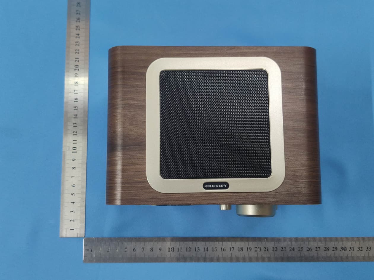
Click to zoom
Application Details
- Equipment Class
- DXX - Part 15 Low Power Communication Device Transmitter
- Date of Grant
- Jan 11, 2021
- Application Purpose
- Original Equipment
- Date of Application
- Jan 11, 2021
- Equipment Note
- Solo Radio
- Frequency Range
- 2402.00000000 - 2480.00000000
- Country
- United States
Documents & Files
Document Text
Text extracted from the exhibit documents filed with the FCC. Open a document above to read the original.
Users Manual
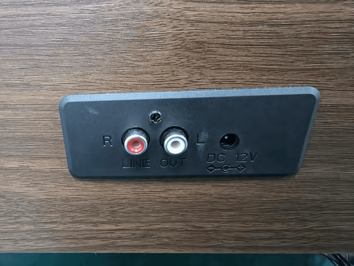
CR3003A Solo Radio Instruction Manual Questions, problems, missing parts? Before returning to the store, call Customer Service 8 a.m. – 8 p.m., EST, Monday – Friday 1-888-CROSLEY www.crosleyradio.com/support English 2 Safety Instructions Read and understand this entire manual before using this product. Keep these instructions for future reference. 1. Do not use this product near water. 2. This product should be operated only by the type of power source indicated on the marking label or in this instruction manual. 3. Do not defeat the safety purpose of the polarized plug. A polarized plug has two blades with one blade wider than the other. This plug will fit into the power outlet only one way. If you are unable to insert the plug fully into the outlet try reversing the plug. If the plug should still fail to fit, contact your electrician. 4. Protect the power cord from being walked on or pinched particularly at plugs, convenience receptacles, and the point where they exit from the product. 5. Do not overload wall outlets, extension cords, or integral convenience receptacles as this can result in a risk of fire or electric shock. 6. Never push objects of any kind into this product through openings as they may touch dangerous voltage points or short-out parts that could result in a fire or electric shock. Never spill liquid of any kind on the product. 7. Do not attempt to service this product yourself as opening or removing covers may expose you to dangerous voltage or other hazards. Refer all servicing to qualified service personnel. 8. Changes or modifications to this unit not expressly approved by the party responsible for compliance could void the user’s authority to operate the equipment. 9. Do not use attachments not recommended by the product manufacturer as they may cause hazards. 10. A product and cart combination should be moved with care. Quick stops, excessive force, and uneven surfaces may cause the product and cart combination to overturn. 11. Slots and openings in the cabinet are provided for ventilation and to ensure reliable operation of the product and to protect it from overheating. Do not block or cover these openings. 12. Unplug the product during lightning storm or when unused for long periods of time. English 3 Items in this package Before throwing away any packaging materials, please check thoroughly and make sure you find the following items that come along with this package: Radio 3.5mm aux in cable Power adaptor Please contact Crosley customer service if there is any accessory missing from the package. Retain the original packaging materials for exchange or return purposes. Specifications Power AC power adaptor, DC output 12V 1A Power consumption 15W Speaker 3”, 8 Ω, 5 W x 1 Frequency Range FM 88-108MHz AM 530-1700KHz Note: Design and specifications are subject to change without notice. English 4 Product Description 1. Dial Scale 2. Tuning Knob 3. Function Knob 4. Power Indicator 5. Tuning Indicator 6. Volume Knob 7. Antenna 8. Power Jack 9. Line Out Jack 10. Aux In Jack 11. Headphone Jack English 5 Initial Setup Essential Setup 1. Place the unit on a flat and level surface. The selected location should be stable and free from vibration. 2. Connect AC adaptor to the Power Jack of the unit. Note: Do not plug the AC power adaptor to power outlet before all the assembly is completed. Before turning the power on, make sure again all the connection settings are correct. Always turn off the power when connecting or disconnecting. Aux Input Connection You can connect an audio device to this unit and play your music through its speaker. To do this, rotate the Function Knob to Aux In mode, connect the 3.5mm auxiliary cable between your audio device and the Aux In Jack of this unit and start playing. Radio Operation 1. Rotate the Function Knob to FM or AM position. 2. Rotate the Tuning Knob for desired radio station. Note: The unit is equipped with a FM antenna. To FM improve reception, move the antenna around until the reception is clear without interferences. The AM antenna is built inside the unit. If AM reception is poor, try to rotate the unit for better reception. Troubleshooting There is no power Power adaptor is not connected correctly. No power at the power outlet. There is no sound Function Knob is in the AUX position English 6 FCC Statements This equipment has been tested and found to comply with the limits for a Class B digital device, pursuant to Part 15 of the FCC Rules. These limits are designed to provide reasonable protection against harmful interference in a residential installation. This equipment generates, uses, and can radiate radio frequency energy and, if not installed and used in accordance with the instructions, may cause harmful interference to radio communications. However, there is no guarantee that interference will not occur in a particular installation. If this equipment does cause harmful interference to radio or television reception, which can be determined by turning the equipment off and on, the user is encouraged to try to correct the interference by one or more of the following measures: Reorient or relocate the receiving antenna. Increase the separation between the equipment and receiver. Connect the equipment into a circuit different from that to which the receiver is connected. Consult the dealer or an experienced radio TV technician for help. CR3003A Radio Solo Manuel d’utilisation Des questions, problèmes, pièces manquantes? Avant de retourner au magasin, appelez le service à la clientèle De 8 h à 20 h, HNE, du lundi au vendredi 1-888-CROSLEY www.crosleyradio.com/support Français 2 Instructions de sécurité Veuillez lire et comprendre l'intégralité de ce manuel avant d'utiliser ce produit. Conservez ces instructions pour pouvoir les consulter ultérieurement. 1. Ne pas utiliser ce produit près de l’eau. 2. Ce produit doit être alimenté uniquement par le type de source d’alimentation indiqué sur l’étiquette ou…
Text truncated - open the document above for the full version.
Cover Letter(s)
Modern Marketing Concepts, Inc. Agent Authorization Company: Modern Marketing Concepts, Inc. Address: 1220 E Oak, St. Louisville, Kentucky 40204, United States Product Name: Solo Radio Model Number(s): CR3003B-WA, CR3003B-BK, CR3003X-XXXX X-XXXX can be replaced by letter from"A"to"Z", number from"0"to"9"or blank. Product Description: Solo Radio We authorize MiCOM Labs Inc., 575 Boulder Court, Pleasanton, California 94566, USA, to act on our behalf on all matters concerning the certification of above named equipment. We declare that MiCOM Labs Inc. is allowed to forward all information related to the approval and certification of equipment to the regulatory agencies as required and to discuss any issues concerning the approval application. Any and all acts carried out by MiCOM Labs on our behalf shall have the same effect as acts of our own. Signature: Date: 2020-12-29 Name: Scott McWhorter Title: Director of Engineering Company: Modern Marketing Concepts, Inc.
Cover Letter(s)
Differences Declaration To whom concern, We company Modern Marketing Concepts, Inc.hereby declares: The product models CR3003B-WA, CR3003B-BK, CR3003X-XXXX X-XXXX can be replaced by letter from"A"to"Z", number from"0"to"9"or blank. are identical in the same PCB layout, interior structure and electrical circuits, The differences are appearance color and model name for commercial purpose. Authorized signature: Date: 2020-12-29
Cover Letter(s)
ModernMarketingConcepts,Inc. OfficeofEngineeringTechnology FederalCommunicationsCommission 7435OaklandMillsRoad Columbia,MD21046 USA Date:2020-12-29 Subject;RequestforConfidentiality FCCID:AUSCR3003B ToWhomItMayConcern, PursuanttotheprovisionsoftheCommission’srulesTitle47Sections§0.457and§0.459,we arerequestingtheCommissiontowithholdthefollowingattachment(s)asconfidential documentsfrompublicdisclosureindefinitely. Thesedocumentscontaindetailedsystemandequipmentdescriptionsandareconsideredas proprietaryinformationinoperationoftheequipment.Thepublicdisclosureofthesedocuments mightbeharmfultoourcompanyandwouldgivecompetitorsanunfairadvantageinthemarket. SchematicDiagram BlockDiagram PartsList OperationalDescription Tune-upProcedure Inadditionaltoabovementioneddocuments,inordertocomplywiththemarketingregulations inTitle47CFR§2.803andtheimportationrulesinTitle47CFR§2.1204,whileensuringthat businesssensitiveinformationremainsconfidentialuntiltheactualmarketingofnewly authorizeddevices,werequestShortTermConfidentialityofthefollowingattachment(s); ExternalPhotos TestSetupPhotos InternalPhotos UserManual For45days,pursuanttoPublicNoticeDA04-1705. OR For180dayspursuanttoKDB726920D01. Itisourunderstandingthatallmeasurementtestreports,FCCIDlabelformatand correspondenceduringthecertificationreviewprocesscannotbegrantedasconfidential documentsandthisinformationwillbeavailableforpublicreviewoncethegrantofequipment authorizationisissued. Sincerely, Signature: Name:ScottMcWhorter Title:DirectorofEngineering
External Photos
Test Model No.: CR3003B-WA
ID Label/Location Info
Model No.:CR3003B-WA Label location
ID Label/Location Info
Solo Radio Model :CR3003B-WA Rating: DC 5V 2A FCC ID: AUSCR3003B This device complies with part 15 of the FCC Rules. Operation is subject to the following two conditions: (1) This device may not cause harmful interference, and (2) this device must accept any interference received, including interference that may cause undesired operation. Solo Radio Model : CR3003B-BK Rating: DC 5V 2A FCC ID: AUSCR3003B This device complies with part 15 of the FCC Rules. Operation is subject to the following two conditions: (1) This device may not cause harmful interference, and (2) this device must accept any interference received, including interference that may cause undesired operation.
Internal Photos
Test Model No.: CR3003B-WA
Test Report
Global United Technology Services Co., Ltd. Report No.: GTS202011000316F01 Authorized Signature: Robinson Luo Laboratory Manager This results shown in this test report refer only to the sample(s) tested, this test report cannot be reproduced, except in full, without prior written permission of the company. The report would be invalid without specific stamp of test institute and the signatures of compiler and approver. Page 1 of 28 + TEST REPORT Applicant: Modern Marketing Concepts, Inc. Address of Applicant: 1220 E Oak, St. Louisville, Kentucky 40204, United States Manufacturer/Factory: Timsen Development Limited Address of Manufacturer/Factory: 5F, 447# Tianhebei Road, Guangzhou, China Equipment Under Test (EUT) Product Name: Solo Radio Model No.: CR3003B-WA, CR3003B-BK, CR3003X-XXXX X-XXXX can be replaced by letter from"A"to"Z", number from"0"to"9"or blank. Trade Mark: CROSLEY FCC ID: AUSCR3003B Applicable standards: FCC CFR Title 47 Part 15 Subpart C Section 15.249 Date of sample receipt: November 27, 2020 Date of Test: November 27, 2020-December 16, 2020 Date of report issued: December 16, 2020 Test Result : PASS * * In the configuration tested, the EUT complied with the standards specified above. Report No.: GTS202011000316F01 Global United Technology Services Co., Ltd. No. 123- 128, Tower A, Jinyuan Business Building, No.2, Laodong Industrial Zone, Xixiang Road, Baoan District, Shenzhen, Guangdong, China 518102 Telephone: +86 (0) 755 2779 8480 Fax: +86 (0) 755 2779 8960 Page 2 of 28 2 Version Version No. Date Description 00 December 16, 2020 Original Prepared By: Date: December 16, 2020 Project Engineer Check By: Date: December 16, 2020 Reviewer Report No.: GTS202011000316F01 Global United Technology Services Co., Ltd. No. 123- 128, Tower A, Jinyuan Business Building, No.2, Laodong Industrial Zone, Xixiang Road, Baoan District, Shenzhen, Guangdong, China 518102 Telephone: +86 (0) 755 2779 8480 Fax: +86 (0) 755 2779 8960 Page 3 of 28 3 Contents Page 1 COVER PAGE ............................................................................................................................................ 1 2 VERSION .................................................................................................................................................. 2 3 CONTENTS .............................................................................................................................................. 3 4 TEST SUMMARY ..................................................................................................................................... 4 4.1 MEASUREMENT UNCERTAINTY ............................................................................................................ 4 5 GENERAL INFORMATION ...................................................................................................................... 5 5.1 GENERAL DESCRIPTION OF EUT ......................................................................................................... 5 5.2 TEST MODE ........................................................................................................................................ 7 5.3 DESCRIPTION OF SUPPORT UNITS ....................................................................................................... 7 5.4 DEVIATION FROM STANDARDS ............................................................................................................. 7 5.5 ABNORMALITIES FROM STANDARD CONDITIONS ................................................................................... 7 5.6 TEST FACILITY .................................................................................................................................... 8 5.7 TEST LOCATION ................................................................................................................................. 8 5.8 ADDITIONAL INSTRUCTIONS ................................................................................................................. 8 6 TEST INSTRUMENTS LIST ..................................................................................................................... 9 7 TEST RESULTS AND MEASUREMENT DATA .................................................................................... 11 7.1 ANTENNA REQUIREMENT ................................................................................................................... 11 7.2 CONDUCTED EMISSIONS ................................................................................................................... 12 7.3 RADIATED EMISSION METHOD ........................................................................................................... 15 7.3.1 Field Strength of The Fundamental Signal ................................................................................ 17 7.3.2 Spurious emissions .................................................................................................................... 18 7.3.3 Bandedge emissions.................................................................................................................. 23 7.4 20DB OCCUPY BANDWIDTH .............................................................................................................. 25 8 TEST SETUP PHOTO ............................................................................................................................ 28 9 EUT CONSTRUCTIONAL DETAILS ..................................................................................................... 28 Report No.: GTS202011000316F01 Global United Technology Services Co., Ltd. No. 123- 128, Tower A, Jinyuan Business Building, No.2, Laodong Industrial Zone, Xixiang Road, Baoan District, Shenzhen, Guangdong, China 518102 Telephone: +86 (0) 755 2779 8480 Fax: +86 (0) 755 2779 8960 Page 4 of 28 4 Test Summary Test Item Section in CFR 47 Result Antenna requirement 15.203 Pass AC Power Line Conducted Emission 15.207 Pass Field …
Text truncated - open the document above for the full version.
Test Setup Photos
Test Model No.: CR3003B-WA Radiated Emission Conducted Emission
Contact Information
Applicant
Scott McWhorter(Director of Engineering)
Technical Contact
Test Firm
Global United Technology Services Co. Ltd.Robinson Lo
Technical Specifications
| # | Rule Parts | Frequency Range | Power Output |
|---|---|---|---|
| 1 | 15C | 2.40 GHz - 2.48 GHz | - |
Other Applications from Modern Marketing Concepts, Inc.
AUSCR7023AV2
Sep 15, 2026SERENADE 8-IN-1 RECORED PLAYER
Equipment Class
DTS - Digital Transmission System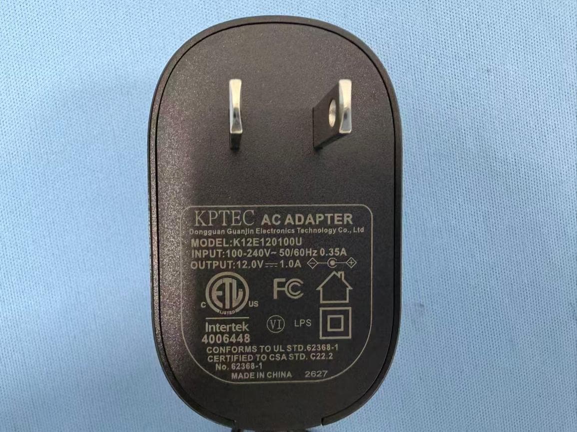
AUSCR31DV2
Sep 03, 2026COMPANION RADIO
Equipment Class
DSS - Part 15 Spread Spectrum Transmitter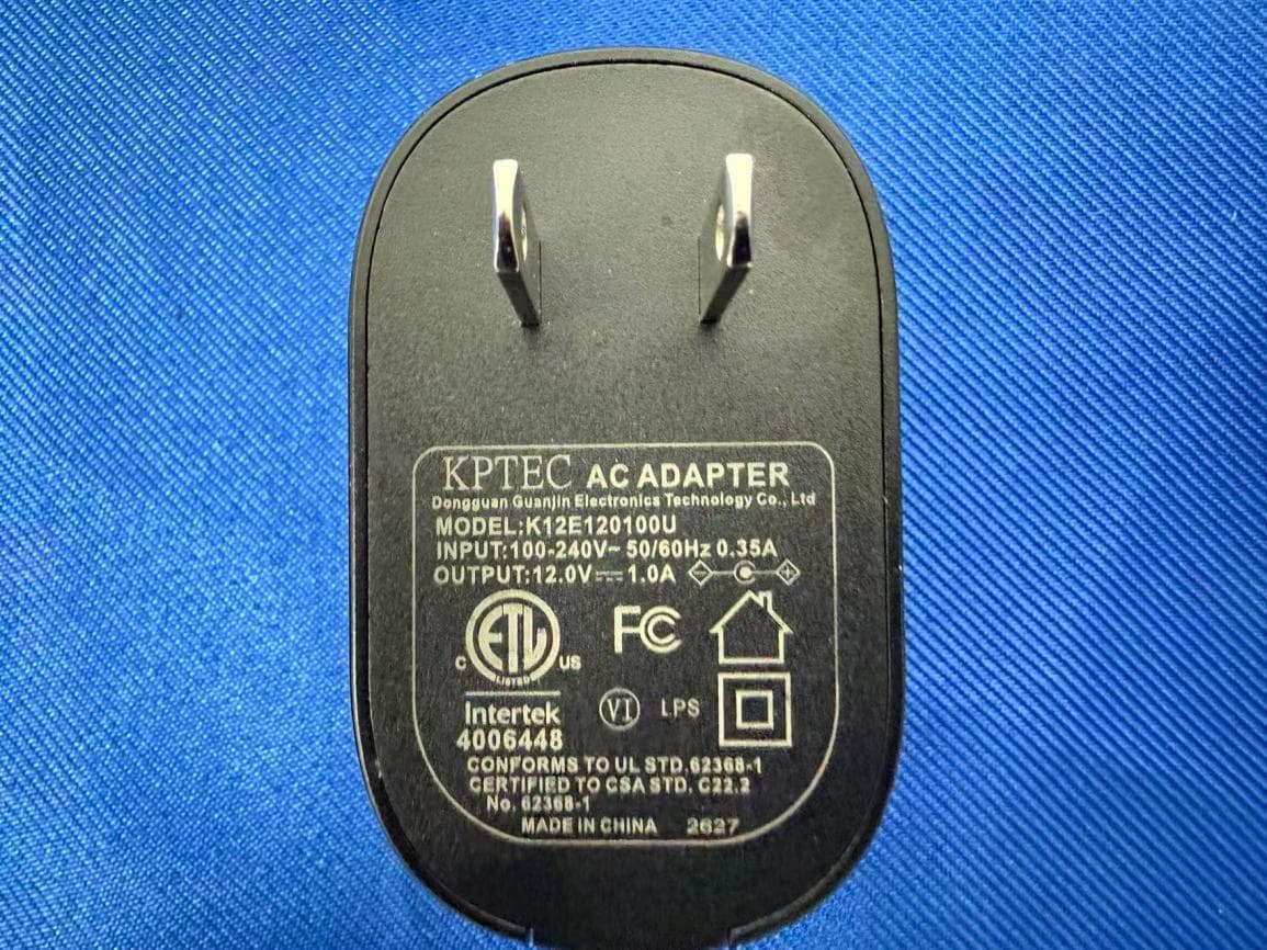
AUSCR32DV2
Sep 02, 2026CATHEDRAL RADIO CD PLAYER
Equipment Class
DSS - Part 15 Spread Spectrum TransmitterAUSCR3506A
Aug 11, 2026VIBE CD PLAYER
Equipment Class
DSS - Part 15 Spread Spectrum Transmitter
AUSCR8009TB
Jun 18, 2026Discovery Turntable
Equipment Class
DSS - Part 15 Spread Spectrum Transmitter