AUSCR6040AVIBE TURNTABLE / RYDER TURNTABLE
Modern Marketing Concepts, Inc.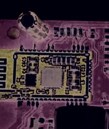
Click to zoom
Application Details
- Equipment Class
- DSS - Part 15 Spread Spectrum Transmitter
- Date of Grant
- Aug 11, 2020
- Application Purpose
- Original Equipment
- Date of Application
- Aug 11, 2020
- Equipment Note
- VIBE TURNTABLE / RYDER TURNTABLE
- Frequency Range
- 2402.00000000 - 2480.00000000
- Country
- United States
Documents & Files
Document Text
Text extracted from the exhibit documents filed with the FCC. Open a document above to read the original.
Users Manual
CR6040A Ryder Turntable Instruction Manual Questions, problems, missing parts? Before returning to the store, call Customer Service 8 a.m. – 6 p.m., EST, Monday – Friday 1-888-CROSLEY www.crosleyradio.com Safety Instructions Read and understand this entire manual before using this product. Keep these instructions for future reference. 1. Do not use this product near water. 2. This product should be operated only by the type of power source indicated on the marking label or in this instruction manual. 3. Do not defeat the safety purpose of the polarized plug. A polarized plug has two blades with one blade wider than the other. This plug will fit into the power outlet only one way. If you are unable to insert the plug fully into the outlet try reversing the plug. If the plug should still fail to fit, contact your electrician. 4. Protect the power cord from being walked on or pinched particularly at plugs, convenience receptacles, and the point where they exit from the product. 5. Do not overload wall outlets, extension cords, or integral convenience receptacles as this can result in a risk of fire or electric shock. 6. Never push objects of any kind into this product through openings as they may touch dangerous voltage points or short-out parts that could result in a fire or electric shock. Never spill liquid of any kind on the product. 7. Do not attempt to service this product yourself as opening or removing covers may expose you to dangerous voltage or other hazards. Refer all servicing to qualified service personnel. 8. Changes or modifications to this unit not expressly approved by the party responsible for compliance could void the user’s authority to operate the equipment. 9. Do not use attachments not recommended by the product manufacturer as they may cause hazards. 10. A product and cart combination should be moved with care. Quick stops, excessive force, and uneven surfaces may cause the product and cart combination to overturn. 11. Slots and openings in the cabinet are provided for ventilation and to ensure reliable operation of the product and to protect it from overheating. Do not block or cover these openings. 12. Unplug the product during lightning storm or when unused for long periods of time. Items in this package Before throwing away any packaging materials, please check thoroughly and make sure you find the following items that come along with this package: ? • Turntable ? • 45 RPM adapter ? • Power adaptor Please contact Crosley customer service if there is any accessory missing from the package. Retain the original packaging materials for exchange or return purposes. Specifications Power AC power adaptor, DC output 5V 1A Power consumption 5W Speaker 4Ω, 5W Turntable speed 331/3, 45, 78 RPM Replacement needle Crosley NP6 Note: ? • Design and specifications are subject to change without notice. ? • To help save power consumption, some models will comply with ERP energy saving standard. When there is no audio input for 20 minutes, their powers will automatically cut-off. To turn power back on and resume playing, you will need to turn off the power and turn it on again. Product Description 1. Turntable Platter 2. Turntable Spindle 3. Tonearm 4. Auto-stop Switch 5. Speed Switch 6. Hold Down Clip 7. Tonearm Rest 8. Function Switch 9. On/Off-Volume Knob 10. Headphone Jack 11. Power Jack 12. Function Indicator 13. RCA Jacks 14. Aux In Jack 15. 45 RPM Adapter Initial Setup Essential Setup 1. Place the unit on a flat and level surface. The selected location should be stable and free from vibration. 2. Remove the tie-wrap that is holding the tonearm. 3. Connect AC adaptor to the Power Jack of the unit. Note: Do not plug the AC power adaptor to power outlet before all the assembly is completed. Before turning the power on, make sure again all the connection settings are correct. Always turn off the power when connecting or disconnecting. Stereo System Connection RCA Jacks ? • The RCA Jacks output analog line-level signals and could be connected directly with a pair of active/powered speakers or the appropriate input of your stereo system. ? • The Red plug connects with the Right channel and the White plug connects with the Left channel. Note: The RCA Jacks are not designed to be connected directly to the passive/unpowered speakers. If connected to the passive speakers, the volume level will be very low. Aux Input Connection You can connect an audio device to this unit and play your music through its speakers. To do this, connect the 3.5mm auxiliary cable between your audio device and the Aux In Jack of this unit and start playing the music. Note: The aux in connection will automatically override the turntable and Bluetooth functions. To resume using the turntable or Bluetooth functions, unplug the auxiliary cable from the aux in jack. The Function Indicator will be purple. Turntable Operation 1. Rotate the On/Off Volume Knob to turn on the power. 2. Set the Function Switch to PHONO position. Note: The Function Indicator will be red. 3. Set the Speed Switch accordingly. 4. Place the record on the turntable. Use the 45 RPM Adapter if necessary. 5. Remove the stylus protector from the stylus assembly. Note: To avoid stylus damage, make certain the included stylus guard is in place whenever the turntable is being moved or cleaned. 6. Release the tonearm Hold Down Clip. Note: when the turntable is not in use, remember to lock back hold down clip. 7. Lift up the Tonearm and move it over the record where play is desired to begin. Gently put down the Tonearm and begin the playback. 8. When the record is finished playing, gently lift up the Tonearm and move it back to the Tonearm Rest. 9. Lock the Tonearm Clip to secure the tonearm. Platter Auto-stop If the Auto-stop Switch is set to ON position, the platter will stop spinning automatically when the record plays to the end. In some rare occasion, if the turntable stops playing before the end of the record, set the switch to OFF position th…
Text truncated - open the document above for the full version.
External Photos
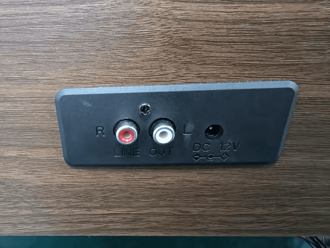
Reference N Waltek Tes http://www EXHIBI EUT View 1 EUT View 2 No.: WTH20X sting Group w.semtest.co T 2 - EUT 1 2 X07043932W (Shenzhen) m.cn T EXTER W-1 Co., Ltd. RNAL PH HOTOGR APHS Reference N Waltek Tes http://www EUT View 3 EUT View 4 No.: WTH20X sting Group w.semtest.co 3 4 X07043932W (Shenzhen) m.cn W-1 Co., Ltd. Reference N Waltek Tes http://www EUT View 5 EUT View 6 No.: WTH20X sting Group w.semtest.co 5 6 X07043932W (Shenzhen) m.cn W-1 Co., Ltd. Reference N Waltek Tes http://www EUT View 7 No.: WTH20X sting Group w.semtest.co 7 X07043932W (Shenzhen) m.cn W-1 Co., Ltd. Reference N Waltek Tes http://www Adapter M o No.: WTH20X sting Group w.semtest.co odel X07043932W (Shenzhen) m.cn W-1 Co., Ltd.
ID Label/Location Info
Reference N Waltek Tes http://www EXHIBI Proposed Specificatio n it is visible durable to r expected lif e Proposed No.: WTH20X sting Group w.semtest.co T 1 - PRO FCC ID La ns: The label or easily acc emain fully l etime. Label Loca X07043932W (Shenzhen) m.cn ODUCT L abel Forma shall be secu cessible to th legible and in ation on EU W-1 Co., Ltd. LABELIN at urely affixed t he user, and ntact on the UT FCC NG to a permane shall not be device in al l ID Label Lo ently attached readily detac l normal cond cation d part of the d chable. The l ditions of use device, in a lo label shall be e throughout ocation where e sufficiently t the device’s e y s
Internal Photos
Reference N Waltek Tes http://www EXHIBI EUT Housi n Solder Boa r No.: WTH20X sting Group w.semtest.co T 3 - EUT ng and Boar rd-Compone X07043932W (Shenzhen) m.cn T INTER rd View 1 ent View 1 W-1 Co., Ltd. NAL PHO OTOGRA APHS Reference N Waltek Tes http://www Solder Boa r Solder Boa r No.: WTH20X sting Group w.semtest.co rd-Compone rd-Compone X07043932W (Shenzhen) m.cn ent View 2 ent View 3 W-1 Co., Ltd. Reference N Waltek Tes http://www Solder Boa r Antenna V i No.: WTH20X sting Group w.semtest.co rd-Compone iew B X07043932W (Shenzhen) m.cn ent View 4 Bluetooth Ant W-1 Co., Ltd. tenna
RF Exposure Info
1. MAXIMUM PERMISSIBLE EXPOSURE (MPE) 1.1 General Information Client Information Applicant: Modern Marketing Concepts,Inc. Address of applicant: 1220 E Oak,St.Louisville Kentucky United States 40204 Manufacturer: Shenzhen Jiayinking Technology Holding Company Limited Address of manufacturer: No.11,11-1, Anye Road, Anliang village, Yuanshan Town, Longgang District, Shenzhen, China General Description of EUT: Product Name: VIBE TURNTABLE / RYDER TURNTABLE Brand Name: CROSLEY Model No.: TT503-1N Adding Model(s): CR6040A-XX ("XX "can be replaced by letter from "A" to "Z", number from "0"to "9" or blank) FCC ID: AUSCR6040A Rated Voltage: DC5V Adapter Model #1: MODEL: JS005SPS-050100U INPUT: AC100-240V, 50/60Hz, 0.2A OUTPUT: DC5V,1A Adapter Model #2: MODEL:THX-050100KV INPUT:100-240V~50/60Hz 065A MAX OUTPUT:DC5V,1A Adapter Model #3: MODEL:GKYZA0100050US INPUT:100-240V~50/60Hz 0.5A MAX OUTPUT:DC5V,1A Technical Characteristics of EUT: Bluetooth Version: V5.0 (BR/EDR mode) Frequency Range: 2402-2480MHz RF Output Power: 5.48dBm (Conducted) Data Rate: 1Mbps, 2Mbps, 3Mbps Modulation: GFSK, Pi/4 DQPSK, 8DPSK Quantity of Channels: 79 Channel Separation: 1MHz Type of Antenna: PCB Antenna Antenna Gain: 0dBi 1.2 Standard Applicable According to §1.1307(b)(1) and KDB 447498 D01 General RF Exposure Guidance v06, system operating under the provisions of this section shall be operating in a manner that the public is not exposed to radio frequency energy level in excess limit for maximum permissible exposure. (a) Limits for Occupational / Controlled Exposure Frequency range (MHz) Electric Field Strength (E) (V/m) Magnetic Field Strength (H) (A/m) Power Density (S) (mW/cm 2 ) Averaging Times | E | 2 , | H | 2 or S (minutes) 0.3-3.0 614 1.63 (100)* 6 3.0-30 1842/f 4.89/f (900/f)* 6 30-300 61.4 0.163 1.0 6 300-1500 / / F/300 6 1500-100000 / / 5 6 (b) Limits for General Population / Uncontrolled Exposure Frequency range (MHz) Electric Field Strength (E) (V/m) Magnetic Field Strength (H) (A/m) Power Density (S) (mW/cm 2 ) Averaging Times | E | 2 , | H | 2 or S (minutes) 0.3-1.34 614 1.63 (100)* 30 1.34-30 824/f 2.19/f (180/f)* 30 30-300 27.5 0.073 0.2 30 300-1500 / / F/1500 30 1500-100000 / / 1 30 Note: f = frequency in MHz: * = Plane-wave equivalents power density 1.3 MPE Calculation Method S = (30*P*G) / (377*R 2 ) S = power density (in appropriate units, e.g., mw/cm 2 ) P = power input to the antenna (in appropriate units, e.g., mw) G = power gain of the antenna in the direction of interest relative to an isotropic radiator, the power gain factor is normally numeric gain. R = distance to the center of radiation of the antenna (in appropriate units, e.g., cm) 1.4 MPE Calculation Result Maximum Tune-Up output power: 6 (dBm) Maximum peak output power at antenna input terminal: 3.98(mW) Prediction distance: >20(cm) Prediction frequency: 2480 (MHz) Antenna gain:0 (dBi) Directional gain (numeric gain): 1 The worst case is power density at prediction frequency at 20cm: 0.0008 (mw/cm 2 ) MPE limit for general population exposure at prediction frequency: 1 (mw/cm 2 ) Result: Pass
Test Report
Waltek Testing Group (Shenzhen) Co., Ltd. http://www.semtest.com.cn Page 1 of 53 TEST REPORT Reference No. .................... : WTH20X07043932W-1 FCC ID ................................ : AUSCR6040A Applicant ........................... : Modern Marketing Concepts,Inc. Address ............................. : 1220 E Oak,St.Louisville Kentucky United States 40204 Product Name ................... : VIBE TURNTABLE / RYDER TURNTABLE Test Model. ........................ : TT503-1N Standards .......................... : FCC Part 15.247 Date of Receipt sample .... : Jul.09, 2020 Date of Test........................ : Jul.09, 2020 to Jul.29, 2020 Date of Issue ..................... : Jul.29, 2020 Test Result ......................... : Pass Remarks: The results shown in this test report refer only to the sample(s) tested, this test report cannot be reproduced, except in full, without prior written permission of the company. The report would be invalid without specific stamp of test institute and the signatures of compiler and approver. Prepared By: Waltek Testing Group (Shenzhen) Co., Ltd. Address: 1/F., Room 101, Building 1, Hongwei Industrial Park, Liuxian 2nd Road, Block 70 Bao'an District, Shenzhen, Guangdong, China Tel.: +86-755-33663308 Fax.: +86-755-33663309 Tested by: Reviewed By: Approved & Authorized By: Mike Shi / Project Engineer Lion Cai / RF Manager Silin Chen / Manager Reference No.: WTH20X07043932W-1 Page 2 of 53 Waltek Testing Group (Shenzhen) Co., Ltd. http://www.semtest.com.cn TABLE OF CONTENTS 1. GENERAL INFORMATION ................................................................................................................................... 5 1.1 PRODUCT DESCRIPTION FOR EQUIPMENT UNDER TEST (EUT) ............................................................................... 5 1.2 TEST STANDARDS ................................................................................................................................................... 6 1.3 TEST METHODOLOGY ............................................................................................................................................. 6 1.4 TEST FACILITY ....................................................................................................................................................... 7 1.5 EUT SETUP AND TEST MODE ................................................................................................................................. 7 1.6 MEASUREMENT UNCERTAINTY .............................................................................................................................. 8 1.7 TEST EQUIPMENT LIST AND DETAILS ..................................................................................................................... 9 2. SUMMARY OF TEST RESULTS ......................................................................................................................... 11 3. RF EXPOSURE ....................................................................................................................................................... 12 3.1 STANDARD APPLICABLE ....................................................................................................................................... 12 3.2 TEST RESULT........................................................................................................................................................ 12 4. ANTENNA REQUIREMENT ................................................................................................................................ 13 4.1 STANDARD APPLICABLE ....................................................................................................................................... 13 4.2 EVALUATION INFORMATION ................................................................................................................................ 13 5. FREQUENCY HOPPING SYSTEM REQUIREMENTS ................................................................................... 14 5.1 STANDARD APPLICABLE ....................................................................................................................................... 14 5.2 FREQUENCY HOPPING SYSTEM............................................................................................................................. 14 5.3 EUT PSEUDORANDOM FREQUENCY HOPPING SEQUENCE .................................................................................... 15 6. QUANTITY OF HOPPING CHANNELS AND CHANNEL SEPARATION ................................................... 16 6.1 STANDARD APPLICABLE ....................................................................................................................................... 16 6.2 TEST SETUP BLOCK DIAGRAM ............................................................................................................................. 16 6.3 TEST PROCEDURE ................................................................................................................................................. 16 6.4 SUMMARY OF TEST RESULTS/PLOTS .................................................................................................................... 17 7. DWELL TIME OF HOPPING CHANNEL .......................................................................................................... 20 7.1 STANDARD APPLICABLE ....................................................................................................................................... 20 7.2 TEST SETUP BLOCK DIAGRAM ............................................................................................................................. 20 7.3 TEST PROCEDURE ................................................................................................................................................. 20 7.4 SUMMARY OF TEST RESULTS/PLOTS ...........................................................…
Text truncated - open the document above for the full version.
Test Setup Photos
Reference N Waltek Tes http://www EXHIBI Conducted Radiation E No.: WTH20X sting Group w.semtest.co T 4 - TES Emission Te Emission Tes X07043932W (Shenzhen) m.cn ST SETUP est Setup st Setup (Belo W-1 Co., Ltd. P PHOTO ow 30MHz) OGRAPH HS Reference N Waltek Tes http://www Radiation E Radiation E No.: WTH20X sting Group w.semtest.co Emission Tes Emission Tes X07043932W (Shenzhen) m.cn st Setup (30M st Setup (1GH W-1 Co., Ltd. MHz to 1GHz Hz to 18GHz z) z) Reference N Waltek Tes http://www Radiation E No.: WTH20X sting Group w.semtest.co Emission Tes X07043932W (Shenzhen) m.cn st Setup (Abo W-1 Co., Ltd. ove 18GHz)
Contact Information
Applicant
Scott McWhorter(Director of Engineering)
Test Firm
Waltek Testing Group (Shenzhen) Co., Ltd.Jandy So
Technical Specifications
| # | Rule Parts | Frequency Range | Power Output |
|---|---|---|---|
| 1 | 15C | 2.40 GHz - 2.48 GHz | 3.50 mW |
Other Applications from Modern Marketing Concepts, Inc.
AUSCR7023AV2
Sep 15, 2026SERENADE 8-IN-1 RECORED PLAYER
Equipment Class
DTS - Digital Transmission System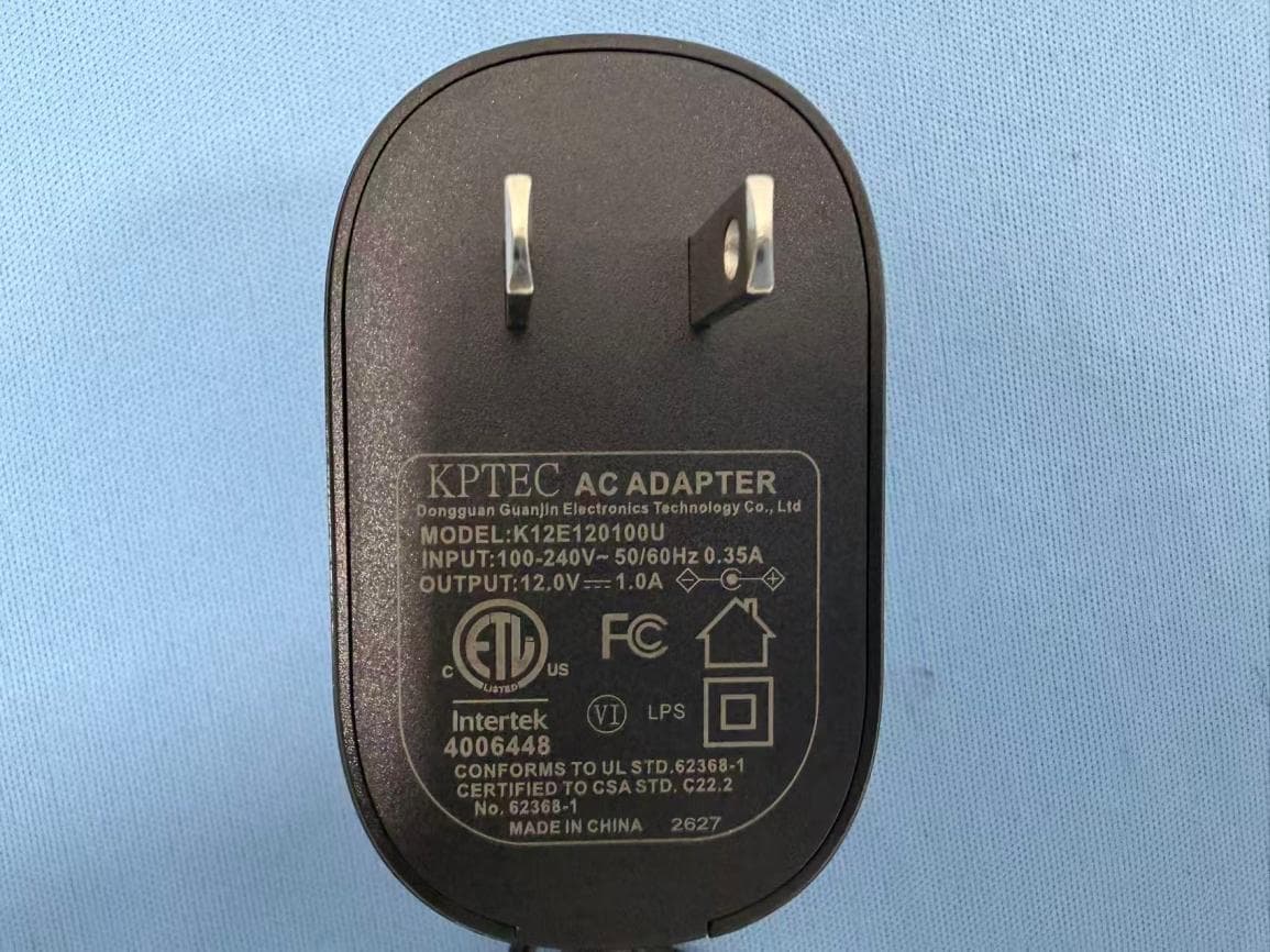
AUSCR31DV2
Sep 03, 2026COMPANION RADIO
Equipment Class
DSS - Part 15 Spread Spectrum Transmitter
AUSCR32DV2
Sep 02, 2026CATHEDRAL RADIO CD PLAYER
Equipment Class
DSS - Part 15 Spread Spectrum TransmitterAUSCR3506A
Aug 11, 2026VIBE CD PLAYER
Equipment Class
DSS - Part 15 Spread Spectrum Transmitter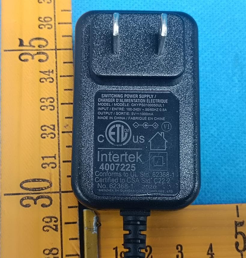
AUSCR8009TB
Jun 18, 2026Discovery Turntable
Equipment Class
DSS - Part 15 Spread Spectrum Transmitter