AUSCR6049ABeck Fully Automatic Vertical Record Player
Modern Marketing Concepts, Inc.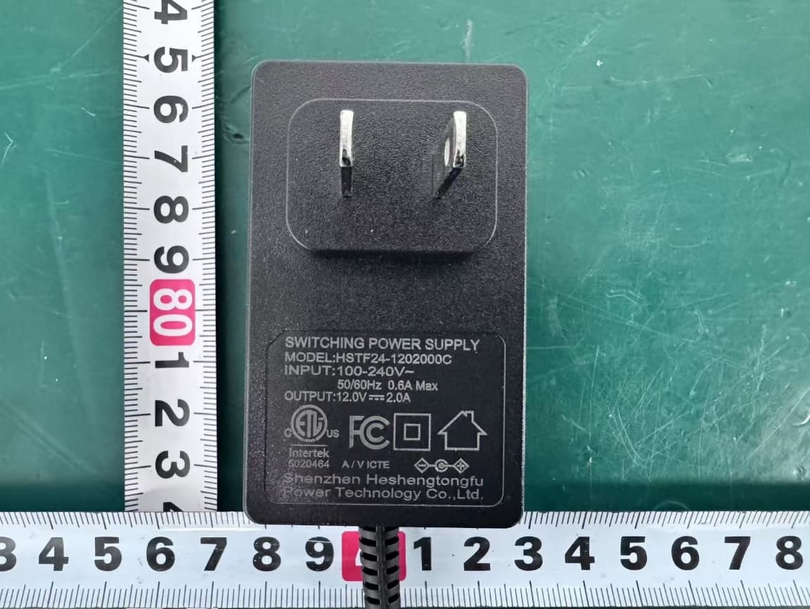
Click to zoom
Application Details
- Equipment Class
- DTS - Digital Transmission System
- Date of Grant
- Sep 30, 2025
- Application Purpose
- Original Equipment
- Equipment Note
- Beck Fully Automatic Vertical Record Player
- Frequency Range
- 2402.00000000 - 2480.00000000
- Country
- United States
Documents & Files
Document Text
Text extracted from the exhibit documents filed with the FCC. Open a document above to read the original.
Users Manual
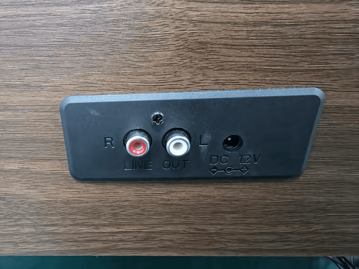
CR6049A Beck Fully Automatic Vertical Record Player Instruction Manual Questions, problems, missing parts? Before returning to the store, call Customer Service 8 a.m. – 6 p.m., EST, Monday – Friday 1-888-CROSLEY www.crosleyradio.com English 2 Safety Instructions Read and understand this entire manual before using this product. Keep these instructions for future reference. 1. Do not use this product near water. 2. This product should be operated only by the type of power source indicated on the marking label or in this instruction manual. 3. Do not defeat the safety purpose of the polarized plug. A polarized plug has two blades with one blade wider than the other. This plug will fit into the power outlet only one way. If you are unable to insert the plug fully into the outlet try reversing the plug. If the plug should still fail to fit, contact your electrician. 4. Protect the power cord from being walked on or pinched particularly at plugs, convenience receptacles, and the point where they exit from the product. 5. Do not overload wall outlets, extension cords, or integral convenience receptacles as this can result in a risk of fire or electric shock. 6. Never push objects of any kind into this product through openings as they may touch dangerous voltage points or short-out parts that could result in a fire or electric shock. Never spill liquid of any kind on the product. 7. Do not attempt to service this product yourself as opening or removing covers may expose you to dangerous voltage or other hazards. Refer all servicing to qualified service personnel. 8. Changes or modifications to this unit not expressly approved by the party responsible for compliance could void the user’s authority to operate the equipment. 9. Do not use attachments not recommended by the product manufacturer as they may cause hazards. 10. A product and cart combination should be moved with care. Quick stops, excessive force, and uneven surfaces may cause the product and cart combination to overturn. 11. Slots and openings in the cabinet are provided for ventilation and to ensure reliable operation of the product and to protect it from overheating. Do not block or cover these openings. 12. Unplug the product during lightning storm or when unused for long periods of time. English 3 Items in this package Before throwing away any packaging materials, please check thoroughly and make sure you find the following items that come along with this package: • Turntable • Magnetic Holder • Power adaptor • RCA Cable • Remote Control • Turntable Platter • Drive Belt Please contact Crosley customer service if there is any accessory missing from the package. Retain the original packaging materials for exchange or return purposes. Specifications Power AC power adaptor, DC output 12V 2A Power consumption 20W Speaker 2” 4Ω 10W x 2 Turntable speed 33 1 / 3 , 45 RPM Replacement needle Crosley NP-5 Note: • Design and specifications are subject to change without notice. • To help save power consumption, some models will comply with ERP energy saving standard. When there is no audio input for 20 minutes, their powers will automatically cut-off. To turn power back on and resume playing, you will need to turn off the power and turn it on again. English 4 Product Description 1. Tonearm 2. Tonearm Clip 3. Tonearm Rest 4. Speed Switch 5. Size Selector 6. Repeat Button 7. Backward Skip Button 8. Forward Skip Button 9. Play/Pause Button 10. Stop Button 11. Power /Volume/ Mode Knob 12. Magnetic Holder 13. Line Out Jacks 14. Aux In Jack 15. Headphone Jack 16. Power Jack English 5 17. Power Button 18. Stop Button 19. Mode Button 20. Up Button 21. Backward Skip Button 22. Forward Skip Button 23. Play/Pause Button 24. Down Button 25. Volume - Button 26. Volume + Button 27. Repeat Button 28. Bluetooth Button 29. Mute Button English 6 Initial Setup Essential Setup 1. Place the unit on a flat and level surface. The selected location should be stable and free from vibration. 2. Remove the tie-wrap that is holding the tonearm. 3. Connect power adaptor to the Power Jack of the unit. 4. Long press the Power button to turn the unit on and off. Note: Do not plug the AC power adaptor to power outlet before all the assembly is completed. Before turning the power on, make sure again all the connection settings are correct. Always turn off the power when connecting or disconnecting. Turntable Platter and Belt Setup 1. Put the drive belt around the Turntable Hub. 2. Insert the turntable platter into the turntable’s spindle hole midway, pull the belt and fit it around the motor pulley slot. 3. Once the belt is attached, push the turntable platter completely into place. Gently rotate the platter a few turns to ensure the belt is secure. Stereo System Connection Line Out Jacks • The Line Out Jacks output analog line-level signals and could be connected directly with a pair of active/powered speakers or the appropriate input of your stereo system. • The Red plug connects with the Right channel and the White plug connects with the Left channel. Note: The Line Out Jacks are not designed to be connected directly to the passive/unpowered speakers. If connected to the passive speakers, the volume level will be very low. This function is available only in Phono mode. English 7 Aux Input Connection Aux Input Connection You can connect an audio device to this unit and play your music through its speakers. To do this, press the Mode button to Aux mode, connect a 3.5mm auxiliary cable (not included) between your audio device and the Aux In Jack of this unit and start playing. Note: The Function Indicator will be Pink. Turntable Operation 1. Long press the Power button to turn the unit on. 2. Press the Mode button and select the Phono mode. Note: The Function Indicator will be White. 3. Set the Size Selector and the Speed Selector to the appropriate record size. Note: 331/3 RPM is size 12” and 45 RPM is 7”. 4. Place the record on the turntable and secure it using the magnetic …
Text truncated - open the document above for the full version.
Attestation Statements
Modern Marketing Concepts, Inc. * the applicant must designate a contact located in the United States for purposes of acting as the applicant’s agent for service of process, regardless of whether the applicant is a domestic or foreign entity. An applicant located in the United States may designate itself as the agent for service of process. U.S. Agent Designation for Service of Process - Certification Attestation Letter 5/22/2025 Federal Communications Commission Authorization and Evaluation Division 7435 Oakland Mills Road Columbia, MD 21046 USA ATTN.: Reviewing Engineer FCC ID: AUSCR6049A Applicant of FRN: 0021475454 Per section 2.911(d)(7) of the FCC rules, Modern Marketing Concepts, Inc. (“the applicant”) certifies that the equipment for which authorization is sought is designated to the following U.S. agent* for service of process: Company Name: Modern Marketing Concepts, Inc. FCC Registration Number (FRN): 0021475454 Physical U.S. Company Address: 1220 E Oak, St., Louisville, Kentucky, United States Contact Person: Scott McWhorter Agent Email Address: [email protected] Telephone Number: +1-502-212-4291 The above contact person accepts the obligation for service of process. The applicant accepts to maintain an agent for no less than one year after the grantee has terminated all marketing and importation or the conclusion of any Commission-related proceeding involving the equipment. Applicant Signed: Agent Signed (if different to Applicant): Signed: Printed name: Scott McWhorter Printed name: Click here to enter text. Title: Director of Engineering Title: Click here to enter text. Company Name: Modern Marketing Concepts, Inc. Company Name: Click here to enter text. Date: 5/22/2025 Date: Click here to enter a date.
Attestation Statements
Modern Marketing Concepts, Inc. Covered Equipment Certification Attestation Letter 5/22/2025 Federal Communications Commission Authorization and Evaluation Division 7435 Oakland Mills Road Columbia, MD 21046 USA ATTN.: Reviewing Engineer FCC ID: AUSCR6049A Modern Marketing Concepts, Inc. (“the applicant”) certifies that the equipment for which authorization is sought is not “covered” equipment prohibited from receiving an equipment authorization pursuant to section 2.903 of the FCC rules. Note: If the equipment for which the applicant seeks authorization is produced by any of the entities identified on the current Covered List, the applicant should include an explanation on why the equipment is not “covered” equipment. Modern Marketing Concepts, Inc. (“the applicant”) certifies that, as of the date of the filing of the application, the applicant is not identified on the Covered List (as a specifically named entity or any of its subsidiaries or affiliates) as an entity producing “covered” equipment. Modern Marketing Concepts, Inc. (“the applicant”) certifies that the equipment for which authorization is sought does not include cybersecurity or anti-virus software produced or provided by Kaspersky Lab, Inc. or any of its successors and assignees, including equipment with integrated Kaspersky Lab, Inc. (or any of its successors and assignees) cybersecurity or anti-virus software pursuant to DA-24-886 and KDB 986446 D01 Covered Equipment Guidance section B(2a). Printed name: Scott McWhorter Title: Director of Engineering Company Name: Modern Marketing Concepts, Inc. Date: 5/22/2025
Cover Letter(s)
Modern Marketing Concepts, Inc. I, the signer, Scott McWhorter The only differences between these models are model name. Their enclosure/form factor, internal circuitry/PCB components and hardware/software are identical. Model name difference is for market and commercial purpose. Item Name :Beck Fully Automatic Vertical Record Player Model Number: CR6049A-WA Additional Model: TT49 Name: Scott McWhorter Title: Director of Engineering Company: Modern Marketing Concepts, Inc.
Cover Letter(s)
Modern Marketing Concepts, Inc. DATE : 2025.05.22 Equipment Autorisation Division Federal Communications Commission 7435 Oakland Mills Road Columbia, MD 21046 FCC ID: AUSCR6049A Product Name: Beck Fully Automatic Vertical Record Player Request for Confidentiality Pursuant to Sections 0.457 and 0.459 of the commissions rules, we hereby request that the following documents be held confidential: (List here the documents for which you are seeking confidentiality – for example ...) • Schematics • Block diagram • Operation description These materials contain trade secrets and proprietary information and are not customarily released to the public. The public disclosure of this information might be harmful to the company and provide unjustified benefits to our competitors. Name: Scott McWhorter Title: Director of Engineering Company: Modern Marketing Concepts, Inc.
Cover Letter(s)
Modern Marketing Concepts, Inc. DATE : 2025.5.22 Federal Communications Commission Authorization & Evaluation Division 7345 Oakland Mills Road Columbia, Maryland 21046 Authority to Act as Agent On our behalf, I appoint EST Technology Co., Ltd. Address: Chilingxiang, Qishantou, Santun, Houjie, Dongguan, Guangdong, China (Name of Agent company name and address) to act as our agent in the preparation of this application for equipment certification. I certify that submitted documents properly describe the device or system for which equipment certification is sought. I also certify that each unit manufactured, imported or marketed, as defined in the Federal Communications Commission’s regulations will have affixed to it a label identical to that submitted for approval with this application. For instances where our authorized agent signs the application for certification on our behalf, I acknowledge that all responsibility for complying with the terms and conditions for certification, still resides with Modern Marketing Concepts, Inc. Address: 1220 E Oak, St., Louisville, Kentucky, United States (Applicant Name and address) Name: Scott McWhorter Title: Director of Engineering Company: Modern Marketing Concepts, Inc.
External Photos
External Photos M/N: CR6049A-WA External Photos M/N: CR6049A-WA External Photos M/N: CR6049A-WA External Photos M/N: CR6049A-WA External Photos M/N: CR6049A-WA External Photos M/N: CR6049A-WA
ID Label/Location Info
Rating Label for CR6049A- 7486105 POWER SUPPLY: Adapter(DC 12V2A) POWER CONSUMPTION: 2 0 W 25 WA FCC ID:AUSCR6049A TT49 25-03-27 材质: Model:CR6049A-WA SIZE: 85 X 35mm 25008号单CR6049A-WA(TT49 尺寸:85x35 mm 一式一份,黑底白字,过光胶 )背板铭牌贴纸
Internal Photos
Internal Photos M/N: CR6049A-WA Internal Photos M/N: CR6049A-WA Internal Photos M/N: CR6049A-WA Bluetooth Antenna Internal Photos M/N: CR6049A-WA
RF Exposure Info
Page 1 of 5 Report No. ESTE-R2505062 FCC 47 CFR MPE REPORT Modern Marketing Concepts, Inc. Beck Fully Automatic Vertical Record Player Model Number: CR6049A-WA Additional Model: CR6049A-X, CR6049X-XX(XX-XXXX.. can be replaced by letter from "A" to "Z" number from "0" to "0" or blank) FCC ID: AUSCR6049A Applicant: Modern Marketing Concepts, Inc. Address: 1220 East Oak Street, Louisville, Kentucky 40204 United States Prepared By: EST Technology Co., Ltd. Chilingxiang, Qishantou, Santun, Houjie, Dongguan, Guangdong, China Tel: 86-769-83081888-808 Report Number: ESTE-R2505062 Date of Test: Apr. 03, 2025~ May. 17, 2025 Date of Report: Sep. 28, 2025 Page 2 of 5 Report No. ESTE-R2505062 Maximum Permissible Exposure 1. Applicable Standards Systems operating under the provisions of this section shall be operated in a manner that ensures that the public is not exposed to radio frequency energy level in excess limit for maximum permissible exposure. In accordance with 47 CFR FCC Part 2 Subpart J, section 2.1091 this device has been defined as a mobile device whereby a distance of 0.2m normally can be maintained between the user and the device. 1.1. Limits for Maximum Permissible Exposure (MPE) (a) Limits for Occupational/Controlled Exposure Frequency Range (MHz) Electric Field Strength (E) (V/m) Magnetic Field Strength (H) (A/m) Power Density (S) (mW/cm 2 ) Averaging Times ︱E︱ 2 ,︱H︱ 2 or S (minutes) 0.3-3.0 614 1.63 (100)* 6 3.0-30 1842/f 4.89/f (900/f)* 6 30-300 61.4 0.163 1.0 6 300-1500 F/300 6 1500-10000 5 6 (b) Limits for General Population / Uncontrolled Exposure Frequency Range (MHz) Electric Field Strength (E) (V/m) Magnetic Field Strength (H) (A/m) Power Density (S) (mW/cm 2 ) Averaging Times ︱E︱ 2 ,︱H︱ 2 or S (minutes) 0.3-1.34 614 1.63 (100)* 30 1.34-30 824/f 2.19/f (180/f)* 30 30-300 27.5 0.073 0.2 30 300-1500 F/1500 30 1500-10000 1.o 30 Note: f=frequency in MHz; *Plane-wave equivalent power density Page 3 of 5 Report No. ESTE-R2505062 1.2. MPE Calculation Method E (V/m) = d G × P × 30 Power Density: Pd (W/m 2 ) = 377 E 2 E = Electric Field (V/m) P = Peak RF output Power (W) G = EUT Antenna numeric gain (numeric) d = Separation distance between radiator and human body (m) The formula can be changed to Pd = 2 d × 377 G × P × 30 From the peak EUT RF output power, the minimum mobile separation distance, d=0.2m, as well as the gain of the used antenna, the RF power density can be obtained Page 4 of 5 Report No. ESTE-R2505062 2. Conducted Power Result Mode Frequency (MHz) Peak output power (dBm) Peak output power (mW) GFSK 2402 8.77 7.534 2441 8.22 6.637 2480 6.89 4.887 π/4-DQPSK 2402 8.72 7.447 2441 8.22 6.637 2480 6.78 4.764 8-DPSK 2402 8.69 7.396 2441 8.18 6.577 2480 6.74 4.721 BLE 1M 2402 7.86 6.109 2440 7.55 5.689 2480 6.32 4.285 Page 5 of 5 Report No. ESTE-R2505062 3. Calculated Result and Limit Mode Peak output power (dBm) Target power (dBm) MAX Target power (dBm) Antenna gain Power Density (S) (mW /cm 2 ) Limited of Power Density (S) (mW /cm 2 ) Test Result (dBi) (Linear) GFSK 8.77 8±1 9 3.37 2.173 0.00343 1 Complies π/4-DQPSK 8.72 8±1 9 3.37 2.173 0.00343 1 Complies 8-DPSK 8.69 8±1 9 3.37 2.173 0.00343 1 Complies BLE 1M 7.86 7±1 8 3.37 2.173 0.00273 1 Complies End of Test Report
Test Report
Page 1 of 18 Report No. ESTE-R2505061 Appendix A: DTS Bandwidth Test Result TestMode Antenna Frequency[MHz] DTS BW [MHz] FL[MHz] FH[MHz] Limit[MHz] Verdict BLE_1M Ant1 2402 0.660 2401.685 2402.345 0.5 PASS BLE_1M Ant1 2440 0.693 2439.664 2440.357 0.5 PASS BLE_1M Ant1 2480 0.702 2479.649 2480.351 0.5 PASS Page 2 of 18 Report No. ESTE-R2505061 Test Graphs BLE_1M-Ant1-2402-PASS BLE_1M-Ant1-2440-PASS BLE_1M-Ant1-2480-PASS Page 3 of 18 Report No. ESTE-R2505061 Page 4 of 18 Report No. ESTE-R2505061 Appendix B: Maximum conducted output power Test Result Peak TestMode Antenna Frequency[MHz] Conducted Peak Powert[dBm] Conducted Limit[dBm] Verdict BLE_1M Ant1 2402 7.86 ≤30 PASS BLE_1M Ant1 2440 7.55 ≤30 PASS BLE_1M Ant1 2480 6.32 ≤30 PASS Test Graphs Peak BLE_1M-Ant1-2402-PASS BLE_1M-Ant1-2440-PASS Page 5 of 18 Report No. ESTE-R2505061 BLE_1M-Ant1-2480-PASS Page 6 of 18 Report No. ESTE-R2505061 Appendix C: Maximum power spectral density Test Result TestMode Antenna Frequency[MHz] Result[dBm/3kHz] Limit[dBm/3kHz] Verdict BLE_1M Ant1 2402 -7.89 ≤8.00 PASS BLE_1M Ant1 2440 -8.52 ≤8.00 PASS BLE_1M Ant1 2480 -9.87 ≤8.00 PASS Page 7 of 18 Report No. ESTE-R2505061 Test Graphs BLE_1M-Ant1-2402-PASS BLE_1M-Ant1-2440-PASS BLE_1M-Ant1-2480-PASS Page 8 of 18 Report No. ESTE-R2505061 Page 9 of 18 Report No. ESTE-R2505061 Appendix D: Reference level measurement Test Result TestMode Antenna Freq(MHz) Max.Point[MHz] Result[dBm] BLE_1M Ant1 2402 2402.26 7.65 BLE_1M Ant1 2440 2440.25 7.06 BLE_1M Ant1 2480 2480.02 5.25 Page 10 of 18 Report No. ESTE-R2505061 Test Graphs BLE_1M-Ant1-2402-PASS BLE_1M-Ant1-2440-PASS BLE_1M-Ant1-2480-PASS Page 11 of 18 Report No. ESTE-R2505061 Page 12 of 18 Report No. ESTE-R2505061 Appendix E: Band edge measurements Test Result TestMod e Antenn a ChNam e Frequency[MHz ] RefLevel[dBm ] Result[dBm ] Limit[dBm ] Verdic t BLE_1M Ant1 Low 2402 7.65 -40.19 ≤-12.35 PASS BLE_1M Ant1 High 2480 5.25 -40.89 ≤-14.75 PASS Page 13 of 18 Report No. ESTE-R2505061 Test Graphs BLE_1M-Ant1-2402-PASS BLE_1M-Ant1-2480-PASS Page 14 of 18 Report No. ESTE-R2505061 Appendix F: Conducted Spurious Emission Test Result TestMode Antenna Frequency[MHz] FreqRange [MHz] RefLevel [dBm] Result[dBm] Limit[dBm] Verdict BLE_1M Ant1 2402 30~26500 7.65 -35.59 ≤-12.35 PASS BLE_1M Ant1 2440 30~26500 7.06 -36.24 ≤-12.94 PASS BLE_1M Ant1 2480 30~26500 5.25 -39.12 ≤-14.75 PASS Page 15 of 18 Report No. ESTE-R2505061 Test Graphs BLE_1M-Ant1-2402-30~26500-PASS BLE_1M-Ant1-2440-30~26500-PASS BLE_1M-Ant1-2480-30~26500-PASS Page 16 of 18 Report No. ESTE-R2505061 Page 17 of 18 Report No. ESTE-R2505061 Appendix G: Duty Cycle Test Result TestMode Antenna Frequency[MHz] ON Time [ms] Period [ms] Duty Cycle [%] Duty Cycle Factor[dB] BLE_1M Ant1 2440 2.13 2.50 85.20 0.70 Page 18 of 18 Report No. ESTE-R2505061 Test Graphs NTNV-BLE_1M-Ant1-2440
Test Report
Page 1 of 40 Report No.ESTE-R2505061 FCC PART 15C TEST REPORT FOR CERTIFICATION On Behalf of Modern Marketing Concepts, Inc. Beck Fully Automatic Vertical Record Player Model Number: CR6049A-WA Additional Model: CR6049A-X, CR6049X-XX(XX-XXXX.. can be replaced by letter from "A" to "Z" number from "0" to "0" or blank) FCC ID: AUSCR6049A Applicant: Modern Marketing Concepts, Inc. Address: 1220 East Oak Street, Louisville, Kentucky 40204 United States Prepared By: EST Technology Co., Ltd. Chilingxiang, Qishantou, Santun, Houjie, Dongguan, Guangdong, China Tel: 86-769-83081888-808 Report Number: ESTE-R2505061 Date of Test: Apr. 03, 2025~ May. 17, 2025 Date of Report: May. 20, 2025 Page 2 of 40 Report No.ESTE-R2505061 TABLE OF CONTENTS Description Page TEST REPORT VERIFICATION .......................................................................................................... 3 1. GENERAL INFORMATION ................................................................................................................... 5 1.1. Description of Device (EUT) ............................................................................................................ 5 1.2. Antenna Information ......................................................................................................................... 5 1.3. Information of RF Cable ................................................................................................................... 5 2. SUMMARY OF TEST ........................................................................................................................... 6 2.1. Summary of test result ..................................................................................................................... 6 2.2. Test Facilities ..................................................................................................................................... 7 2.3. Measurement uncertainty ................................................................................................................ 8 2.4. Assistant equipment used for test .................................................................................................. 8 2.5. Block Diagram ................................................................................................................................... 8 2.6. Test Mode .......................................................................................................................................... 9 2.7. Power Setting of Test Software ...................................................................................................... 9 2.8. Duty Cycle .......................................................................................................................................... 9 2.9. Channel List ..................................................................................................................................... 10 2.10. Test Equipment List ...................................................................................................................... 11 3. 6DB BANDWIDTH ............................................................................................................................ 13 3.1. Limit ................................................................................................................................................... 13 3.2. Test Setup ........................................................................................................................................ 13 3.3. Spectrum Analyzer Setting ............................................................................................................ 13 3.4. Test Procedure ................................................................................................................................ 13 3.5. Test Result ....................................................................................................................................... 13 4. MAXIMUM PEAK OUTPUT POWER .................................................................................................. 14 4.1. Limit ................................................................................................................................................... 14 4.2. Test Setup ........................................................................................................................................ 14 4.3. Spectrum Analyzer Setting ............................................................................................................ 14 4.4. Test Procedure ................................................................................................................................ 14 4.5. Test Result ....................................................................................................................................... 14 5. POWER SPECTRAL DENSITY .......................................................................................................... 15 5.1. Limit ................................................................................................................................................... 15 5.2. Test Setup ........................................................................................................................................ 15 5.3. Spectrum Analyzer Setting ............................................................................................................ 15 5.4. Test Procedure ................................................................................................................................ 15 5.5. Test Result ....................................................................................................................................... 15 6. CONDUCTED BAND EDGE .............................................................................................................. 16 6.1. Limit ................…
Text truncated - open the document above for the full version.
Test Report
OTA TEST REPORT TA Technology (Shanghai) Co., Ltd. tested the above equipment in accordance with the requirements in ANSI/IEEE Std 149-2008. The test results show that the equipment tested is capable of demonstrating compliance with the requirements as documented in this report. Performed by: Peng Tao Approved by: Kai Xu TA Technology (Shanghai) Co., Ltd. No.145, Jintang Rd, Tangzhen Industry Park, Pudong Shanghai, China TEL: +86‐021‐50791141/2/3 FAX: +86‐021‐50791141/2/3‐8000 Applicant SHANGHAI MOUNTAIN VIEW SILICON CO LTD Product SMARTRF_BOARD_2In1 Model AT2 Report No. Y2003A0190-T1 Issue Date April 2, 2020 OTA Test Report Report No: Y2003A0190-T1 TA Technology (Shanghai) Co., Ltd. TA-MB-04-008O P age 2 of 19 This report shall not be reproduced except in full, without the written approval of TA Technology (Shanghai) Co., Ltd. TABLE OF CONTENTS 1. Test Laboratory .............................................................................................................................. 3 1.1. Notes of the Test Report ................................................................................................... 3 1.2. Test facility ........................................................................................................................ 3 1.3. Testing Location ................................................................................................................ 3 1.4. Laboratory Environment .................................................................................................... 4 2. General Description of Equipment under Test ............................................................................... 5 2.1. Applicant and Manufacturer Information ............................................................................ 5 2.2. General information ........................................................................................................... 5 2.3. Test Date ........................................................................................................................... 5 2.4. Applied Standards ............................................................................................................. 6 3. Test Conditions .............................................................................................................................. 7 3.1. Test Configuration ............................................................................................................. 7 3.2. Test Measurement ............................................................................................................. 7 4. Test Results ................................................................................................................................... 8 4.1. Gain and Efficiency ............................................................................................................ 8 4.2. Voltage Standing Wave Ratio (VSWR) .............................................................................. 9 4.3. Antenna S11 .................................................................................................................... 12 4.4. Impedance ....................................................................................................................... 15 5. Equipment List ............................................................................................................................. 17 APPENDIX A 3-D Pattern Plots ............................................................................................................. 18 ANNEX A:The EUT Appearance and Test Configuration ................................................................. 19 A.1 Test Configuration .............................................................................................................. 19 OTA Test Report Report No: Y2003A0190-T1 TA Technology (Shanghai) Co., Ltd. TA-MB-04-008O P age 3 of 19 This report shall not be reproduced except in full, without the written approval of TA Technology (Shanghai) Co., Ltd. 1. Test Laboratory 1.1. Notes of the Test Report This report shall not be reproduced in full or partial, without the written approval of TA technology (shanghai) co., Ltd. The results documented in this report apply only to the tested sample, under the conditions and modes of operation as described herein .Measurement Uncertainties were not taken into account and are published for informational purposes only. This report is written to support regulatory compliance of the applicable standards stated above. 1.2. Test facility A2LA (Certificate Number: 3857.01) TA Technology (Shanghai) Co., Ltd. has been listed by American Association for Laboratory Accreditation to perform electromagnetic emission measurement. 1.3. Testing Location Company: TA Technology (Shanghai) Co., Ltd. Address: No.145, Jintang Rd, Tangzhen Industry Park, Pudong Shanghai, China City: Shanghai Post code: 201201 Country: P. R. China Contact: Xu Kai Telephone: +86-021-50791141/2/3 Fax: +86-021-50791141/2/3-8000 Website: http://www.ta-shanghai.com E-mail: [email protected] OTA Test Report Report No: Y2003A0190-T1 TA Technology (Shanghai) Co., Ltd. TA-MB-04-008O P age 4 of 19 This report shall not be reproduced except in full, without the written approval of TA Technology (Shanghai) Co., Ltd. 1.4. Laboratory Environment Temperature Min. =19°C,Max. = 25°C Relative h…
Text truncated - open the document above for the full version.
Contact Information
Applicant
Scott McWhorter(Director of Engineering)
[email protected]Fax: +1-502-212-4291
Test Firm
EST Technology Co., Ltd.Iceman Hu
Technical Specifications
| # | Rule Parts | Frequency Range | Power Output |
|---|---|---|---|
| 1 | 15C | 2.40 GHz - 2.48 GHz | 6.11 mW |
Other Applications from Modern Marketing Concepts, Inc.
AUSCR7023AV2
Sep 15, 2026SERENADE 8-IN-1 RECORED PLAYER
Equipment Class
DTS - Digital Transmission System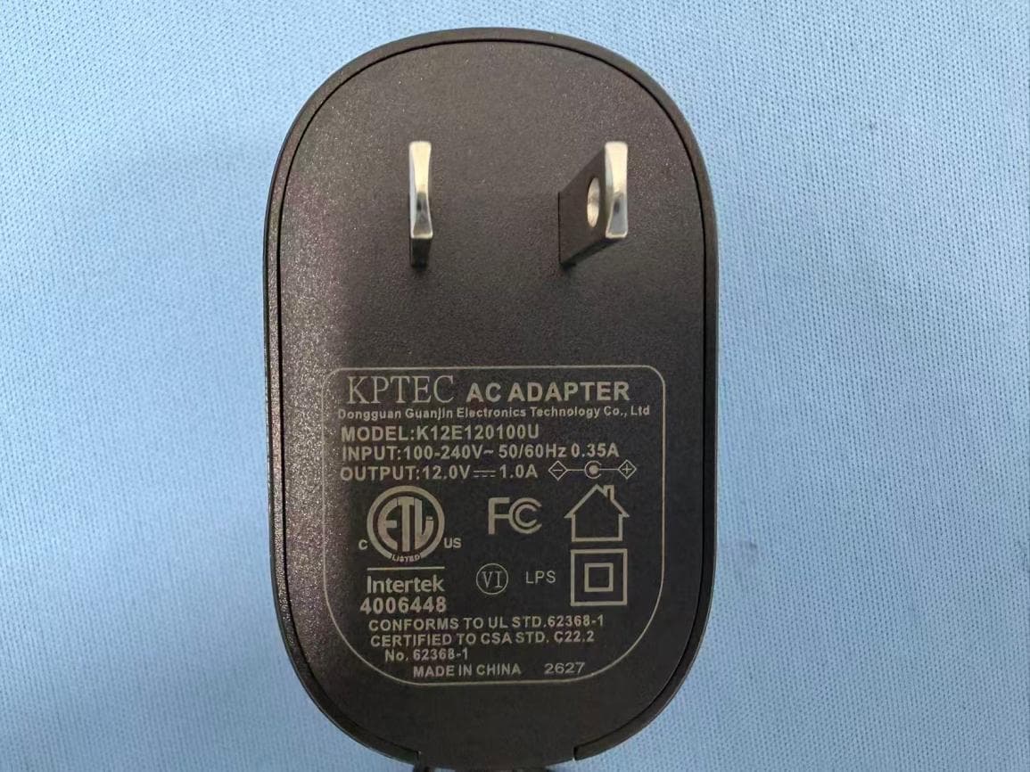
AUSCR31DV2
Sep 03, 2026COMPANION RADIO
Equipment Class
DSS - Part 15 Spread Spectrum Transmitter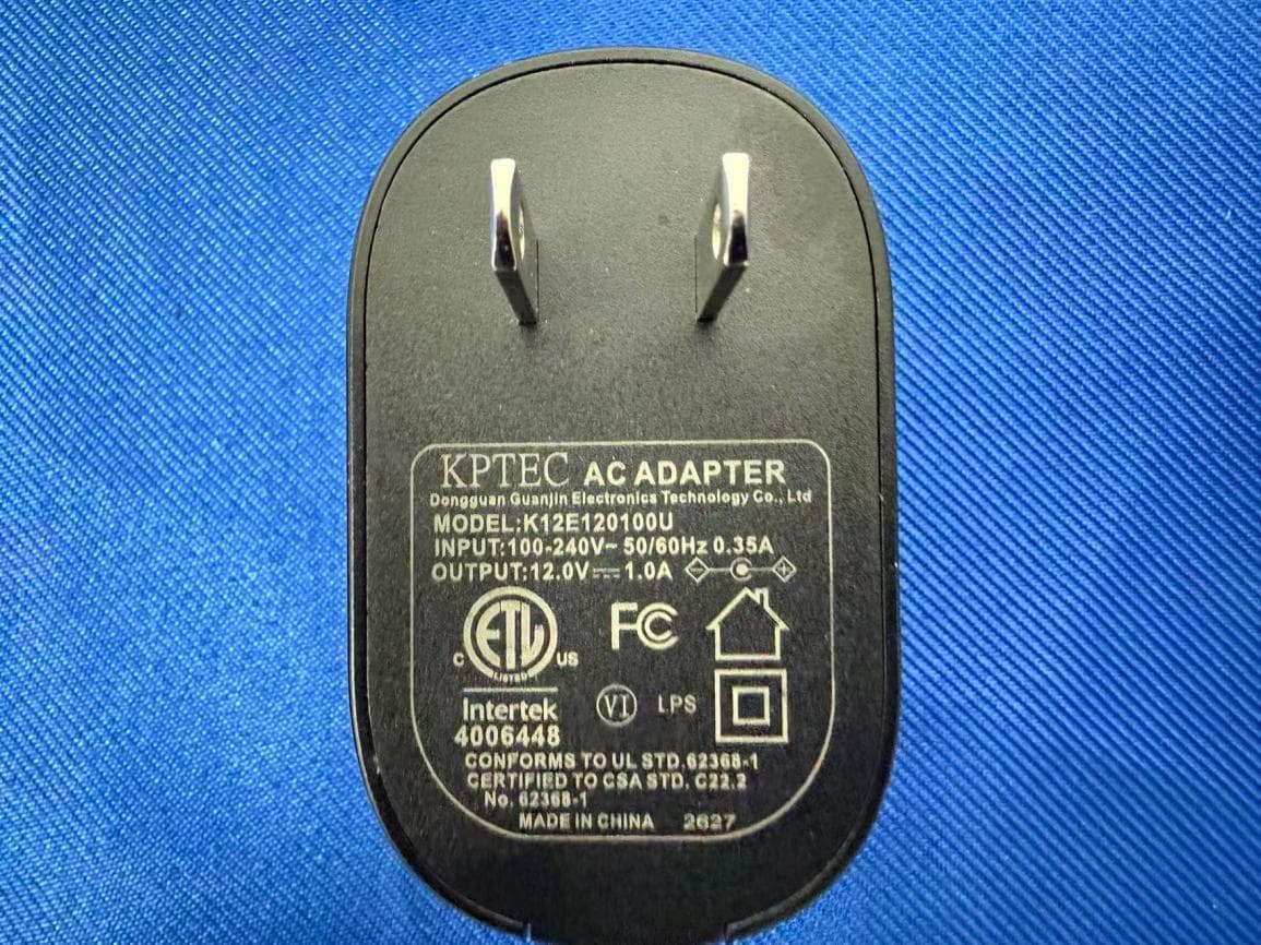
AUSCR32DV2
Sep 02, 2026CATHEDRAL RADIO CD PLAYER
Equipment Class
DSS - Part 15 Spread Spectrum TransmitterAUSCR3506A
Aug 11, 2026VIBE CD PLAYER
Equipment Class
DSS - Part 15 Spread Spectrum Transmitter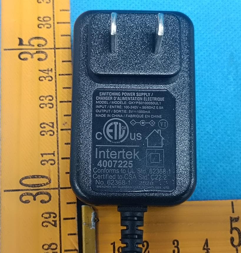
AUSCR8009TB
Jun 18, 2026Discovery Turntable
Equipment Class
DSS - Part 15 Spread Spectrum Transmitter