AVHPCT1Wireless DECT Transceiver
ParTech Inc.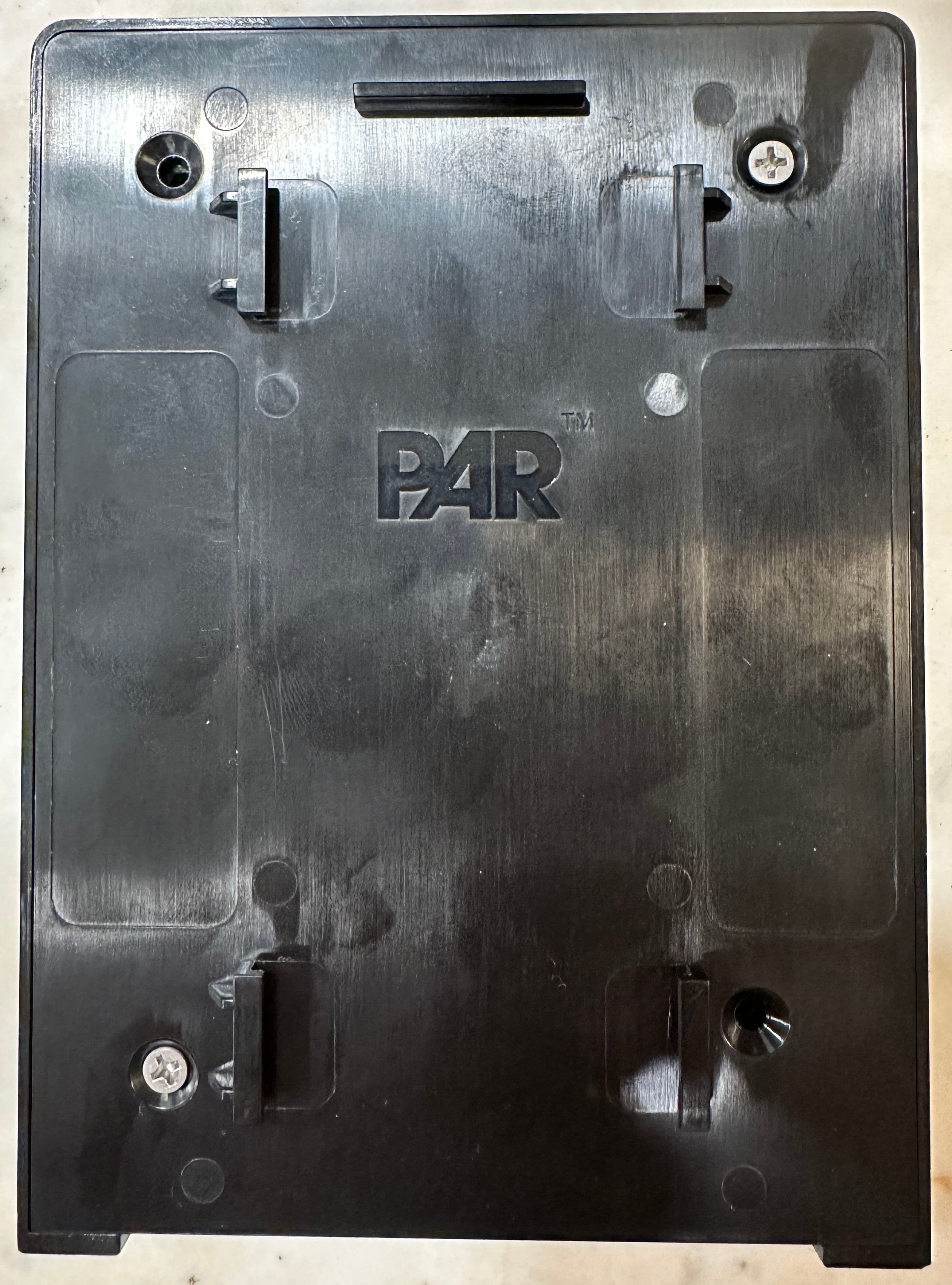
Click to zoom
Application Details
- Equipment Class
- PUB - Part 15 Unlicensed PCS Base Station
- Date of Grant
- Mar 25, 2024
- Application Purpose
- Original Equipment
- Date of Application
- Mar 25, 2024
- Equipment Note
- Wireless DECT Transceiver
- Frequency Range
- 1921.53600000 - 1928.44800000
- Company
- ParTech Inc.
- Country
- United States
Documents & Files
Document Text
Text extracted from the exhibit documents filed with the FCC. Open a document above to read the original.
Users Manual
Page | 1 12/20/23 rev1.5 PAR Clear Transceiver- Quick Reference Installation Guide • Tools and Material Required...................................................................................................................page 1 • Design the Installation..............................................................................................................................page 1 • Install the Transceiver...............................................................................................................................page 2 • Register the Transceiver............................................................................................................................page 3 • Test The Transceiver and Finalize Install..............................................................................................page 3-4 • Transceiver Specifications........................................................................................................................page 4 Tools and Materials Required: • Assortment of sheet metal screws or wall anchors and screws as required by site • Recommend basic tool kit- screwdrivers, hand drill, drill bits • Conduit as needed Design the Installation: The Transceiver should be placed in a location that has the desired range and coverage for the site. Survey the site as needed and test the transmission coverage prior to finalizing the location. 1. Choose the desired location for the Transceiver making sure: a. USB cable is in length to the base station ( place holder, length of USB cable?) b. Use conduit as needed, depending on site Install the Transceiver: 1. Mount the mounting plate of the Transceiver using anchors and screws as needed, do not tighten all the way yet 2. Slide on the Transceiver over the mounting plate Desired Transceiver Location USB Cable Page | 2 12/20/23 rev1.5 3. Plug in the USB cable to the transceiver and the other end of the USB cable to the basestation (make sure the basestation is powered off) Register the Transceiver: 1. Proceed to power on the basestation 2. Observe the LED status of the Transceiver (place holder, XXX LED or sequence) Screws as needed Anchors as needed USB Cable Page | 3 12/20/23 rev1.5 3. Log into the webpage/portal with the provided link and credentials and click on ‘Find connected Transceivers’. Once the Transceiver is connected, a message will pop up saying it was discovered. Test the Transceiver and Finalize Install: 1. Use a registered headset and test the range of the system. (Use the other quick reference guides as needed for the Headset, LAi, and Basestation) **(ensure basestation, LAi, speaker, microphone is also installed) 2. If the system audio and range tests are optimal, proceed to tighten down the screws on the Transceiver mounting plate by sliding the Transceiver out and sliding it back on once the screws are tightened. Otherwise repeat the steps above. Range is optimal per site requirements Page | 4 12/20/23 rev1.5 Transceiver Specifications A. Physical Parameter Specification or Requirement Dimensions (l x w x d) 6 5/8” L x 4 7/8” W x 1 3/8” D Weight 0.3 kg B. Electrical Parameter Specification or Requirement Input Power USB Type B, 5VDC Radio Frequency DECT Maximum Output Power DECT Per Region C. Functional Parameter Specification or Requirement Indicator Red, Green and Blue LED Operating Range =< 2000 meters Operating Temperature 0 to 60 C Tighten screws Page | 5 12/20/23 rev1.5 FCC Compliance Statement This equipment has been tested and found to comply with the limits for a Class A digital device, pursuant to part 15 of the FCC Rules. These limits are designed to provide reasonable protection against harmful interference when the equipment is operated in a commercial environment. This equipment generates, uses, and can radiate radio frequency energy and, if not installed and used in accordance with the instruction manual, may cause harmful interference to radio communications. Operation of this equipment in a residential area is likely to cause harmful interference in which case the user will be required to correct the interference at his own expense. This device complies with Part 15 of the FCC Rules. Operation is subject to the following two conditions: 1. This device may not cause harmful interference, and 2. This device must accept any interference received, including interference that may cause undesired operation. Please note that changes or modifications not expressly approved by the party responsible for compliance could void the user’s authority to operate the equipment. Changes or modifications not expressly approved by the party responsible for compliance could void the user's authority to operate the equipment. ISED non-interference disclaimer This device contains licence-exempt transmitter(s)/receiver(s) that comply with Innovation, Science and Economic Development Canada’s licence-exempt RSS(s). Operation is subject to the following two conditions: (1) This device may not cause interference. (2) This device must accept any interference, including interference that may cause undesired operation of the device. This device complies with the Canadian ICES-003 Class A specifications. CAN ICES-003(B) / NMB-003 (A). L’émetteur/récepteur exempt de licence contenu dans le présent appareil est conforme aux CNR d’Innovation, Sciences et Développement économique Canada applicables aux appareils radio exempt de licence. L’exploitation est autorisée aux deux conditions suivantes : (1) L’appareil ne doit pas produire de brouillage; (2) L’appareil doit accepter tout brouillage radioélectrique subi, même si le brouillage est susceptible d’en compromettre le fonctionnement. Cet appareil numérique de la classe A est conforme à la norme NMB-003 du Canada. CAN ICES-003(B) / NMB-003 (A). ISED/FCC RF Exposure statement This equipment complies with FCC and ISED RSS-102 radiation exposure limits set forth for an uncontrolled environment. This transmitter must not be co-loc…
Text truncated - open the document above for the full version.
Attestation Statements
ParTech, Inc. 8383 Seneca Turnpike New Hartford, NY 13413 partech.com | 800.448.6505 Covered Equipment Certification Attestation Letter December 21, 2023 Nemko North America, Inc. 303 River Road Ottawa K1V 1H2 Canada ATTN.: Reviewing Engineer FCC ID: AVHPCT1 and AVHPCH1 ParTech, Inc. (“the applicant”) certifies that the equipment for which authorization is sought is not “covered” equipment prohibited from receiving an equipment authorization pursuant to section 2.903 of the FCC rules. Note: If the equipment for which the applicant seeks authorization is produced by any of the entities identified on the current Covered List, the applicant should include an explanation on why the equipment is not “covered” equipment. ParTech, Inc. (“the applicant”) certifies that, as of the date of the filing of the application, the applicant is not identified on the Covered List as an entity producing “covered” equipment. Signed: Printed name: Rafael Martinez Title: Sr Compliance Engineer Company Name: ParTech, Inc. Date: 12/20/2023
Attestation Statements
ParTech, Inc. 8383 Seneca Turnpike New Hartford, NY 13413 partech.com | 800.448.6505 U.S. Agent Designation for Service of Process - Certification Attestation Letter December 21, 2023 Nemko North America, Inc. 303 River Road Ottawa K1V 1H2 Canada ATTN.: Reviewing Engineer FCC ID: AVHPCT1 and AVHPCH1 Applicant FRN: 0021475553 Per section 2.911(d)(7) of the FCC rules, ParTech, Inc (“the applicant”) certifies that the equipment for which authorization is sought is designated to the following U.S. Designated agent* for service of process: Company Name: ParTech Inc. Physical U.S. Company Address: 8383 Seneca Turnpike, New Hartford NY 13413 USA Agent name: Rafael Martinez Agent Email Address: [email protected] Agent FRN**: 0021475553 The above contact person accepts the obligation for service of process. The applicant accepts to maintain an agent for no less than one year after the grantee has terminated all marketing and importation or the conclusion of any Commission-related proceeding involving the equipment. Applicant Signed: Designated Agent Signed: (Required, if different to Applicant): Signed: Signed: Printed name: Rafael Martinez Printed name: Click here to enter text. Title: Sr Compliance Engineer Title: Click here to enter text. Company Name: ParTech Inc. Company Name: Click here to enter text. Date: December 20, 2023 Date: Click here to enter a date.
Cover Letter(s)
ParTech, Inc. 8383 Seneca Turnpike New Hartford, NY 13413 partech.com | 800.448.6505 Nemko North America, Inc. 303 River Road, Ottawa, Ontario, Canada K1V 1H2 Attn: Director of Certification Authority to Act as Agent for FCC and ISED application On our behalf, I appoint Spencer Zhong of Nemko Canada, Inc. at 303 River Road, Ottawa, Ontario, Canada K1V 1H2, to act as our agent in the preparation of this application for equipment certification. I certify that submitted documents properly describe the device or system for which equipment certification is sought. I also certify that each unit manufactured, imported or marketed, as defined in FCC and in ISED Canada’s regulations will have affixed to it a label identical to that submitted for approval with this application. In signing this letter, Applicant certifies that neither the applicant nor any party to the application is not subject to a denial of Federal benefits, that include FCC benefits, pursuant to Section 5301 of the Anti-Drug Abuse Act of 1988, 21 U.S.C. § 862 because of a conviction for possession or distribution of a controlled substance. Further, no party, as defined in 47 CFR 1.2002 (b), to the application is subject to denial of federal benefits, that includes FCC benefits. We also declare that the information provided to the FCC is true and correct to the best of our knowledge (47 CFR 2.911(d)) and we have been informed of the grantee responsibilities (47 CFR 2.909) with regard to certified equipment. For instances where our authorized agent signs the application for certification on our behalf, I acknowledge that all responsibility for complying with the terms and conditions for certification, as specified by Nemko Canada Inc, still resides with ParTech, Inc. 8383 Seneca Turnpike, New Hartford NY 13413 Dated: December 21, 2023 Agency agreement expiration date: 2024-12-18 *Up to 12 months Signed by: Rafael Martinez Signature Print name Sr Compliance Engineer Title 315-330-8702 Phone On behalf of: ParTech, Inc. Company name
Cover Letter(s)
ParTech, Inc. 8383 Seneca Turnpike New Hartford, NY 13413 partech.com | 800.448.6505 December 21, 2023 Nemko North America, Inc. 303 River Road, Ottawa, Ontario, Canada K1V 1H2 Attn: Director of Certification Request for Confidentiality – FCC FCC ID: AVHPCT1 and AVHPCH1 Pursuant to FCC 47 CFR 0.457(d)(1)(ii) and 0.459 and FCC guidance published in KDB 726920, we hereby request confidential treatment of information accompanying this application as outlined below. We request the exhibits selected below as long term confidential (LTC) be withheld from public view permanently: Selection of exhibits for LTC - general Exhibit name ☒ Permanent (Long Term) Block Diagrams ☒ Permanent (Long Term) Operation Description / Theory of Operation ☒ Permanent (Long Term) Parts List & Placement / BOM ☒ Permanent (Long Term) Schematics Selection of exhibits for LTC - specific 1 Exhibit name ☐ Permanent (Long Term) Tune-Up Procedure ☐ Permanent (Long Term) SDR 2 Software / Security Info Selection of exhibits for LTC (with NDA) 3 Exhibit name ☐ Permanent (Long Term) User’s Manual ☐ Permanent (Long Term) Internal Photos We also request the exhibits selected below as short term confidential (STC) be withheld from public view for a period of 30 days 4 from the date of the Grant of Equipment Authorization and prior to marketing. This is to avoid premature release of sensitive information prior to marketing or release of the product to the public: Selection of exhibits for STC 5 Exhibit name ☐ Short Term Block Diagrams ☐ Short Term Operation Description / Theory of Operation ☐ Short Term Parts List & Placement / BOM ☐ Short Term Schematics ☐ Short Term User’s Manual ☒ Short Term Internal Photos ☐ Short Term External Photos ☒ Short Term Test Setup Photos ☐ Short Term Tune-Up Procedure (for Licensed equipment only) 1 - Tune up procedure is applicable only for licensed equipment. 2 - The FCC rules require that any radio, in which the software is designed or expected to be modified by a party other than the manufacturer that would affect the operating parameters of frequency range, modulation type, maximum output power or other radio frequency parameters outside the range under which the transmitter has been approved in accordance with the FCC rules, must be certified as a software-defined radio (SDR). 3 - These items require further information to be provided to TCB before permanent confidentiality will be extended to these exhibits. Please refer to FCC KDB 726920 and review section II, 3) regarding specific information (NDA) that must accompany these requests. 4 - Number of days can be listed up to 180 but should not go past the date of beginning of product marketing/sale. 5 - Any exhibits that may have already been requested to have “Permanent” confidentiality need not be repeated under Short-Term confidentiality request. ParTech, Inc. 8383 Seneca Turnpike New Hartford, NY 13413 partech.com | 800.448.6505 Our company has spent a substantial effort in developing this product and it is one of the first of its kind in the industry. Having the subject information easily available to "competition" would negate the advantage they have achieved by developing this product. Not protecting the details of the design will result in financial hardship. When the device is marketed before the requested number of days listed above, the grantee will inform the TCB to release the Short-Term Confidentiality information withheld on the FCC equipment authorization website. The above information contains trade secrets and proprietary information not customarily released to the public. The public disclosure of this information might be harmful to the applicant and provide unjustified benefits to its competitors. The Applicant understands that pursuant to Rule 0.457(d)(1)(ii), disclosure of this Application and all accompanying materials will not be made before the date of the Grant for this Application. Sincerely, Signed by: Rafael Martinez Signature Print name Sr Compliance Engineer Title 315-330-8702 Phone ParTech Inc Company 8383 Seneca Turnpike, New Hartford NY 13413 Address
ID Label/Location Info
Model: WMT P/N: K7807 Input: 5V ParTech, Inc. Assembled in USA with globally sourced components ITE E146430 500mA FCC ID: AVHPCT1 IC: 10329A-PCT1CAN ICES-3/NMB-3 A Modelo: WMT/K7807/PCT1 Marca: PAR IFT: xxxxxxxxxxxxx
RF Exposure Info
FCC ID: AVHPCT1 MPE Calculation for FCC Uncontrolled Environment Formula from page 18 of OET Bulletin 65, Edition 97 -01 where: S = power density P = power input to the antennaG = power gain of the antenna in the direction of i nterest relative to an isotropic radiator R = distance to the center of radiation of the ante nna Source Based Time Averaged Duty Cycle is 100% in ca lculation below Maximum peak output power at antenna input terminal : 15.90 (dBm) Maximum peak output power at antenna input terminal : 0.039 (W) Maximum antenna gain: 2.51 (dBi) Maximum antenna gain: 1.782 (numeric) Prediction distance: 20 (cm) Prediction frequency: 1925 (MHz) Time Averaged Duty Cycle 100 % MPE limit for uncontrolled exposure at prediction f requency: 10.00 (W/m^2) Power density at prediction frequency: 0.0138 (mW/cm^2) Power density at prediction frequency: 0.138 (W/m^2) Maximum allowable antenna gain: 21.11 (dBi) Margin of Compliance: 18.60 (dB) 2 4 R PG S π =
Test Report
REP028183 Template version: D Nemko Group Nemko Scandinavia AS, Instituttveien 6, 2007 Kjeller, Norway TEL +47 22 96 03 30 EMAIL [email protected] nemko.com/no Test Report Product DECT Base Station Name and address of the applicant ParTech, Inc. 8383 Seneca Turnpike, New Hartford NY 13413, USA Name and address of the manufacturer ParTech, Inc. 8383 Seneca Turnpike, New Hartford NY 13413, USA Model PC WMT / PCT1-PAR Clear Wall Mount Transceiver Rating 5.0 V DC , 500 mA Trademark PAR Additional information DECT 6.0 Tested according to FCC Part 15, subpart D Isochronous UPCS Device, 1920 – 1930 MHz ISED Canada RSS-213, Issue 3 2 GHz License-Exempt Personal Communications Services (LE-PCS) Devices Order number PRJ0041321 Tested in period 2023-11-08 to 2024-02-12 Issue date 2024-02-20 Name and address of the testing laboratory Nemko Scandinavia AS Instituttveien 6 2007 Kjeller, Norway www.nemko.com CAB Number: FCC: NO0001 ISED: NO0470 ISED No: 2040D-1 An accredited technical test executed under the Norwegian accreditation scheme Prepared by [Frode Sveinsen] Approved by [Jan G Eriksen] This report was originally distributed electronically with digital signatures. For more information, please contact Nemko Scandinavia AS. TEST REPORT FCC part 15D PRJ0041321 REP028183 FCC ID: AVHPCT1 IC: 10329A-PCT1 Nemko Scandinavia AS Page 2 (38) Revision history Revision Date Comment Sign A 2024-02-20 First edition FS GENERAL REMARKS This report applies only to the sample(s) tested. It is the manufacturer's responsibility to ensure the additional production units of this product are manufactured with identical electrical and mechanical components. The manufacturer is solely responsible for any modifications to the product that could result in non-compliance with the relevant regulations. This report shall not be reproduced except in full without the written approval of Nemko. Any use which a third party makes of this report, or any reliance on or decisions to be made based on it, are the responsibility of such third parties. Nemko Group accepts no responsibility for damage suffered by any third party because of decisions made or actions based on this report. Opinions expressed within this report regarding general assessments and qualifications for PASS or FAIL to the standards limits and requirements, are not part of the current accreditation. Neither are opinions expressed regarding model variants covered by the testing of this report. CALIBRATION All instruments used in the tests given in this test report are calibrated and traceable to national or international standards. Between calibrations all test set-ups are controlled and verified on a regular basis by periodic checks to ensure, with 95% confidence, that the instruments remain within the calibrated levels. MEASUREMENT UNCERTAINTY Measurement uncertainties are calculated or considered for all instruments and instrument set-ups used during these tests. Uncertainty figures are found in a separate clause in this report. TEST REPORT FCC part 15D PRJ0041321 REP028183 FCC ID: AVHPCT1 IC: 10329A-PCT1 Nemko Scandinavia AS Page 3 (38) CONTENTS 1 INFORMATION ................................................................................................................................. 4 1.1 Tested Item ........................................................................................................................................................ 4 1.2 Description of Tested Device .............................................................................................................................. 4 1.3 Test Conditions .................................................................................................................................................. 4 1.4 Test Engineers ................................................................................................................................................... 4 1.5 Digital Modulation Techniques ............................................................................................................................ 4 1.6 Antenna Requirement ......................................................................................................................................... 5 1.7 Channel Frequencies ......................................................................................................................................... 5 1.8 Other Comments ................................................................................................................................................ 5 2 TEST REPORT SUMMARY .............................................................................................................. 6 2.1 General .............................................................................................................................................................. 6 2.2 Test Summary .................................................................................................................................................... 6 3 TEST RESULTS ................................................................................................................................ 8 3.1 Power Line Conducted Emissions ...................................................................................................................... 8 3.2 Automatic Discontinuation of Transmission......................................................................................................... 9 3.3 Peak Power Output .......................................................................................................................................... 10 3.4 Emission Bandwidth B ...................................................................................................................................... 12 3.5 Power Spectral Density ......................................................................................................................…
Text truncated - open the document above for the full version.
Test Setup Photos
TEST SET-UP PHOTOS PRJ0041321 FCC ID: AVHPCT1 Page 1 (1) Nemko Scandinavia AS Power-Line Conducted Emissions Conducted Test
Contact Information
Applicant
Rafael Martinez(Sr Compliance Engineer)
Test Firm
Nemko Scandinavia ASFrode Sveinsen
[email protected]+4796905548
Technical Specifications
| # | Rule Parts | Frequency Range | Power Output | Emission | Tolerance |
|---|---|---|---|---|---|
| 1 | 15D | 1.92 GHz - 1.93 GHz | 39.00 mW | F1D | 2.4000000000 ppm |
Other Applications from ParTech Inc.
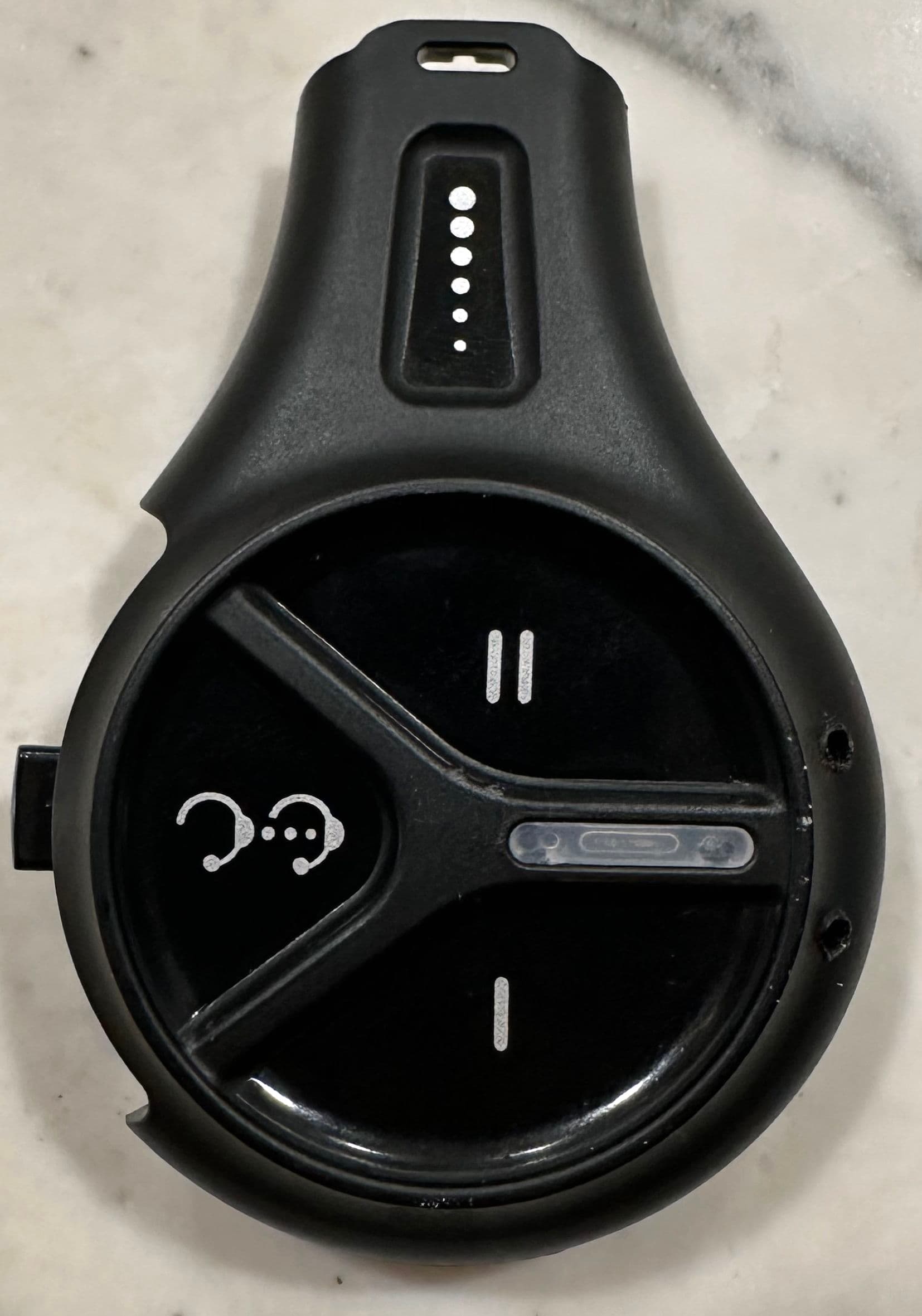
AVHPCH1
Mar 25, 2024Wireless DECT Headset
Equipment Class
PUE - Part 15 Unlicensed PCS portable Tx held to ear
AVHM8936
Sep 25, 2014RFID Reader
Equipment Class
DTS - Digital Transmission System
AVHM8935
Feb 28, 2012Temperature Measuring Device
Equipment Class
DSS - Part 15 Spread Spectrum Transmitter