AXE-EX500Bluetooth Speaker
SHENZHEN SYGAMA TECHNOLOGY CO., LTD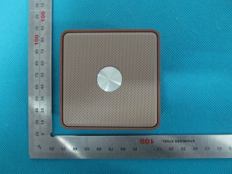
Click to zoom
Application Details
- Equipment Class
- DSS - Part 15 Spread Spectrum Transmitter
- Date of Grant
- Aug 06, 2013
- Application Purpose
- Original Equipment
- Date of Application
- Aug 06, 2013
- Equipment Note
- Bluetooth Speaker
- Frequency Range
- 2402.00000000 - 2480.00000000
- Country
- China
Documents & Files
Document Text
Text extracted from the exhibit documents filed with the FCC. Open a document above to read the original.
Users Manual
Bluetooth speaker User Manual Model name:EX500 FCC ID:AXE‐EX500 IC:11118A‐EX500 Fail to pair IBOMB Cube EX500 Set your 1 Ibomb Cube 1 Audio cable 1 USB cable 1 User manual PAIRING MODE Switch to the "ON" Posting ,IBOMB Cube will make Special sound And LED indicatior light will flash blue indicating that it is in pairing mode. TURN ON/OFF PLAY Turn on Bluetooth on your device and search the “IBOMB EX500”, Select it to connect. The IBOMB Cube will “beep”; indicating that it has successfully paired with you device Make sure the device is in pairing mode and the blue light is flashing. Please reset (on/off)the power switch again. Web: WWW.I-BOMB.COM If you are prompted to enter a password to complete pairing,enter”0000” what’s in the box?what’s in the box? The IBOMB Cube EX500 delivers stunning Hi-fi audio in a portable wireless speaker so Compact you won’t believe it when you hear it IBOMB Cube EX500 Change function mode Hold the Play/Pause button to disconnect the current connection from Wireless to 3.5 jack input device. Vice versa to return back to Wireless connection mode. Playing music with a 3.5mm Cable CHANGE THE MODE (Bluetooth /Audio) PLAY PAUSE PICK UP PHONE NEXT SONG VOLUME UP REPEAT SONG VOLUME DOWN SHORT PRESS LONG PRESS IC: 11118A‐EX500 This device complies with Industry Canada licence‐exempt RSS standard(s). Operation is subject to the following tow conditions: (1) this device may not cause interference, and (2) this device must accept any interference, includinginterference that may cause undesired operation of the device. Cet appareil est conforme avec Industrie Canada RSS standard exempts de licence (s). Son utilisation est soumise à Les deux conditions suivantes: (1) cet appareil ne peut pas provoquer d'interférences et (2) cet appareil doit accepter Toute interférence, y compris les interférences qui peuvent causer un mauvais fonctionnement du dispositif.
Cover Letter(s)
Jul. 31, 2013 Federal Communication Commission Authorization and Evaluation Division FCC ID: AXE-EX500 Re: Confidentiality Request Pursuant to Sections 0.457 and 0.459 of the Commission’s Rules, the applicant hereby requests confidential treatment of information applied this application as outlined below: 1: Block Diagram 2: Circuit Diagram 3: Parts List The above materials contain trade secrets and proprietary information not customarily released to the public. The public disclosure of these matters might be harmful to the applicant and provide unjustified benefits to its competitors. The Applicant understands that pursuant to Rules 0.457, disclosure of this Application and all accompanying documentation will not be made before the date of the Grant for this application. Sincerely, SHENZHEN SYGAMA TECHNOLOGY CO., LTD Contact person: Helen Zhong Title: General manager
External Photos
EX500 External Photos TOTAL VIEW OF EUT TOP VIEW OF EUT BOTTOM VIEW OF EUT FRONT VIEW OF EUT BACK VIEW OF EUT LEFT VIEW OF EUT RIGHT VIEW OF EUT
ID Label/Location Info
FCC ID/IC Label Location Bluetooth speaker Model: EX500 Brand Name: N/A FCC ID: AXE-EX500 IC:11118A-EX500 DIGC001
Internal Photos
EX500 Internal Photos INTERNAL VIEW OF EUT-1 INTERNAL VIEW OF EUT-2 INTERNAL VIEW OF EUT-3 BT Antenna
Operational Description
OPERATIONAL DESCRIPTION The EUT is a Bluetooth speaker designed as a “Communication Device”. It is designed by way of utilizing the FHSS technology to achieve the system operation. A major technical description of EUT is described as following Operation Frequency 2.402 GHz to 2.480GHz RF Output Power 3.98dBm Bluetooth Version V3.0 Modulation GFSK, π /4-DQPSK, 8DPSK Number of channels 79 Antenna Designation Integrated Antenna Antenna Gain 0dBi Power Supply Normal Voltage: DC 5V & Extreme Voltage :DC 4.2 V-DC 5.7V Note: The EUT can be operated during charging via USB port (adaptor or PC connection),the USB port is for charging only.
Test Report
Report No.: AGC00858130701FE01 Page 1 of 53 FCC Test Report Report No.: AGC00858130701FE01 FCC ID : AXE‐EX500 APPLICATION PURPOSE : Original Equipment PRODUCT DESIGNATION : Bluetooth speaker BRAND NAME : N/A MODEL NAME : EX500, DIGC001 CLIENT : Shenzhen Sygama Technology Co.,Ltd DATE OF ISSUE : Jul.24,2013 STANDARD(S) : FCC Part 15 Rules REPORT VERSION : V1.0 Attestation of Global Compliance (Shenzhen) Co., Ltd CAUTION: This report shall not be reproduced except in full without the written permission of the test laboratory and shall not be quoted out of context. Report No.: AGC00858130701FE01 Page 2 of 53 Report Revise Record Report Version Revise Time Issued Date Valid VersionNotes V1.0 / Jul.24,2013 Valid Original Report Report No.: AGC00858130701FE01 Page 3 of 53 TABLE OF CONTENTS 1. VERIFICATION OF CONFORMITY ............................................................................................................ 5 2. GENERAL INFORMATION ........................................................................................................................ 6 2.1. PRODUCT DESCRIPTION ................................................................................................................. 6 2.2. TABLE OF CARRIER FREQUENCYS ................................................................................................ 6 2.3. RECEIVER INPUT BANDWIDTH ....................................................................................................... 7 2.4. EXAMPLE OF A HOPPING SEQUENCY IN DATA MODE .................................................................. 7 2.5. EQUALLY AVERAGE USE OF FREQUENCIES AND BEHAVIOUR ................................................... 7 2.6. RELATED SUBMITTAL(S) / GRANT (S) ............................................................................................. 8 2.7. TEST METHODOLOGY ...................................................................................................................... 8 2.8. SPECIAL ACCESSORIES .................................................................................................................. 8 2.9. EQUIPMENT MODIFICATIONS .......................................................................................................... 8 3. MEASUREMENT UNCERTAINTY ............................................................................................................. 9 4. DESCRIPTION OF TEST MODES ............................................................................................................. 9 5. SYSTEM TEST CONFIGURATION .......................................................................................................... 10 5.1. CONFIGURATION OF EUT SYSTEM ............................................................................................... 10 5.2. EQUIPMENT USED IN EUT SYSTEM .............................................................................................. 10 5.3. SUMMARY OF TEST RESULTS ....................................................................................................... 10 6. TEST FACILITY ........................................................................................................................................ 11 7. PEAK OUTPUT POWER .......................................................................................................................... 12 7.1. MEASUREMENT PROCEDURE ...................................................................................................... 12 7.2. TEST SET-UP (BLOCK DIAGRAM OF CONFIGURATION) ............................................................. 12 7.3. LIMITS AND MEASUREMENT RESULT ........................................................................................... 13 8. 20DB BANDWIDTH ............................................................................................................. ..................... 15 8.1. MEASUREMENT PROCEDURE ...................................................................................................... 15 8.2. TEST SET-UP (BLOCK DIAGRAM OF CONFIGURATION) ............................................................. 15 8.3. LIMITS AND MEASUREMENT RESULTS ........................................................................................ 15 9. CONDUCTED SPURIOUS EMISSION ..................................................................................................... 22 9.1. MEASUREMENT PROCEDURE ...................................................................................................... 22 9.2. TEST SET-UP (BLOCK DIAGRAM OF CONFIGURATION) ............................................................. 22 9.3. MEASUREMENT EQUIPMENT USED ............................................................................................. 22 9.4. LIMITS AND MEASUREMENT RESULT ........................................................................................... 22 10. RADIATED EMISSION ........................................................................................................................... 26 10.1. MEASUREMENT PROCEDURE .................................................................................................... 26 10.2. TEST SETUP .................................................................................................................................. 28 10.3. TEST RESULT ................................................................................................................................ 29 Report No.: AGC00858130701FE01 Page 4 of 53 11. BAND EDGE EMISSION ........................................................................................................................ 33 11.1. MEASUREMENT PROCEDURE ..................................................................................................... 33 11.2. TEST SET-UP ................................................................................................................................. …
Text truncated - open the document above for the full version.
Test Setup Photos
APPENDIX IV PHOTOGRAPHS OF TEST SETUP FCC LINE CONDUCTED EMISSION TEST SETUP FCC RADIATED EMISSION TEST SETUP
Contact Information
Applicant
Helen Zhong(GM)
Test Firm
Attestation of Global Compliance Shenzhen Co. Ltd.Forrest Lei
Technical Specifications
| # | Rule Parts | Frequency Range | Power Output |
|---|---|---|---|
| 1 | 15C | 2.40 GHz - 2.48 GHz | 2.50 mW |
Other Applications from SHENZHEN SYGAMA TECHNOLOGY CO., LTD
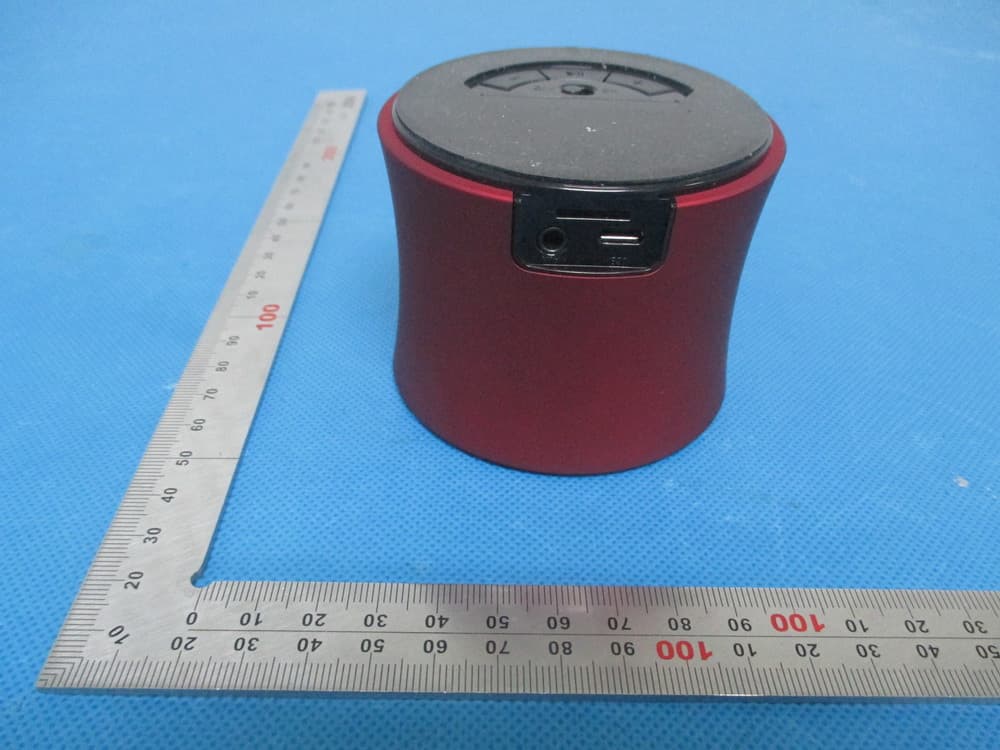
AXE-TRX570
Feb 16, 2014Bluetooth Speaker
Equipment Class
DSS - Part 15 Spread Spectrum Transmitter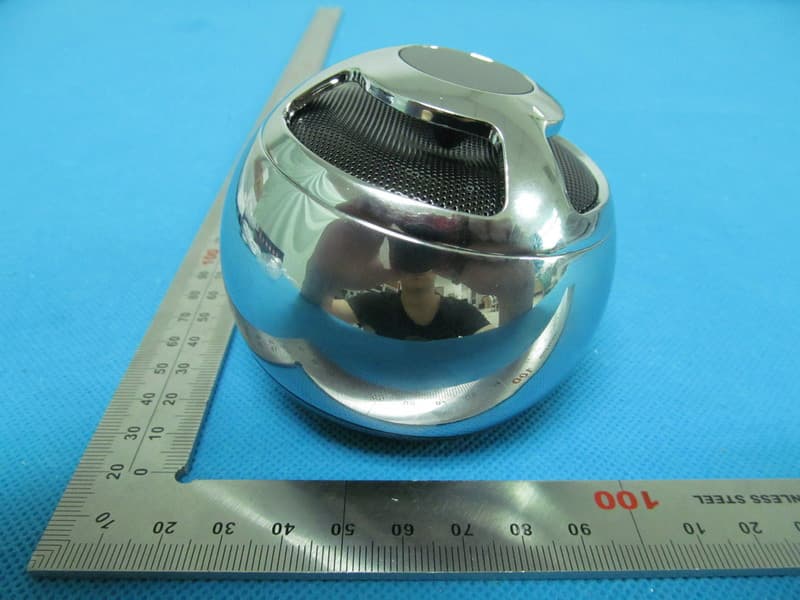
AXE-EX800
Aug 25, 2013Bluetoth Speaker
Equipment Class
DSS - Part 15 Spread Spectrum Transmitter