B3Q5V6102Thermal Printer with Bluetooth
Brother Industries, Ltd.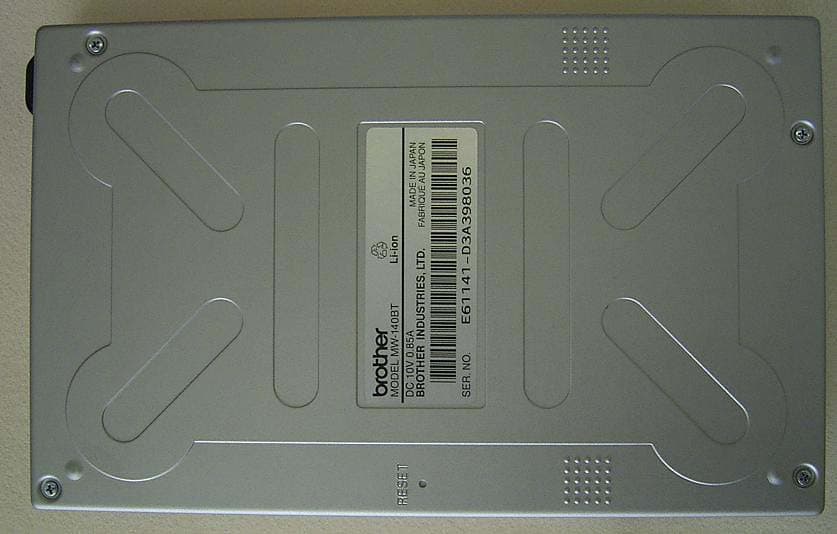
Click to zoom
Application Details
- Equipment Class
- DSS - Part 15 Spread Spectrum Transmitter
- Date of Grant
- Jun 29, 2003
- Application Purpose
- Original Equipment
- Date of Application
- Jun 29, 2003
- Equipment Note
- Thermal Printer with Bluetooth
- Frequency Range
- 2402.00000000 - 2480.00000000
- Company
- Brother Industries, Ltd.
- Country
- Japan
Documents & Files
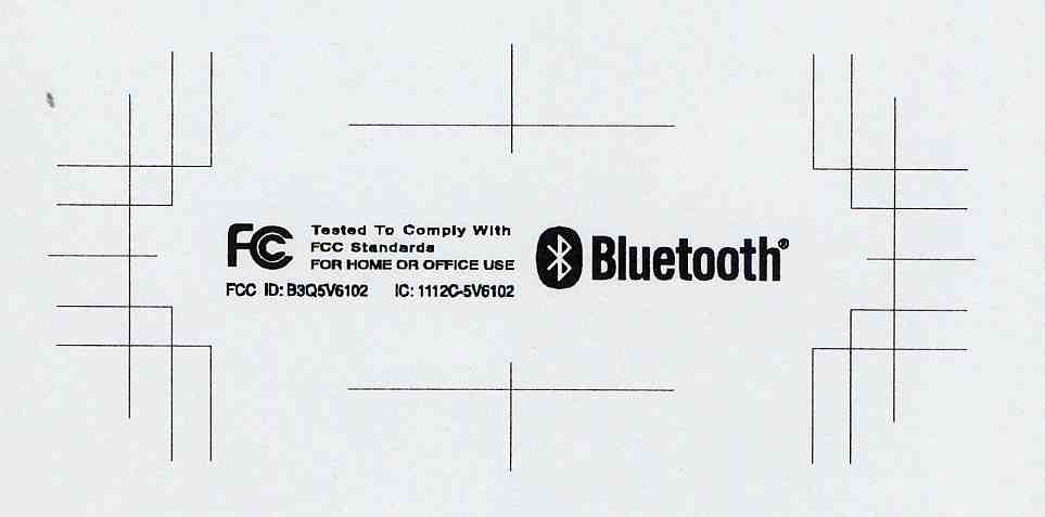
Document Text
Text extracted from the exhibit documents filed with the FCC. Open a document above to read the original.
Users Manual
zBefore using this printer, be sure to read this User’s Guide. zWe suggest that you keep this manual in a handy place for future reference. User’s Guide General Description Operating Procedures Appendix, etc. MW-140BT Mobile Printer MW-140BT_Hardware.book Page 1 Friday, June 13, 2003 10:43 AM MW-140BT_Hardware.book Page 2 Friday, June 13, 2003 10:43 AM Introduction i Thank you for purchasing the MPrint MW-140BT (hereafter referred to as “the printer”). This monochrome thermal mobile printer is ultra-portable and can be connected to a Pocket PC (PDA running Pocket PC) or a computer to make quick printouts. This User’s Guide contains operating precautions and instruc- tions. Before using this printer, be sure to read this manual for information on its correct operation. In addition, we suggest that you keep this manual in a handy place for future reference. Introduction Declaration of Conformity WeBROTHER INDUSTRIES, LTD. 15-1, Naesiro-cho, Mizuho-ku, Nagoya 467-8561, Japan declare that the MPrint MW-140BT conforms with the following normative documents: EMC:EN 55022:1998 Class B EN 55024:1998 EN 61000-3-2:1995 EN 61000-3-3:1995 and follows the provisions of the Electromagnetic Compatibility Directive 89/336/EEC (as amended by 91/263/EEC and 92/31/ EEC). The optional AC adapter also conforms with EN 60950 and follows the provisions of the Low Voltage Directive 73/23/ EEC. Issued by:BROTHER INDUSTRIES, LTD. P & H company Development DIV. MW-140BT_Hardware.book Page i Friday, June 13, 2003 10:43 AM ii { The contents of this manual are subject to change without notice. {The contents of this manual may not be duplicated or repro- duced, partially or in full, without permission. {Please note that we assume no responsibility for damages arising from earthquakes, fire, other disasters, actions of third parties, the user’s intentional or negligent operation, misuse or operation under other special conditions. {Please note that we assume no responsibility for damage (such as losses, loss of business profits, lost profits, business disruptions or a lost means of communication) that may result from the use or inability to use this printer. {If this printer should be defective due to faulty manufacturing, we shall replace it during the warranty period. {We assume no responsibility for damages that may result from incorrect operation of this printer by connecting incompatible equipment or using incompatible software. {This products bearing the CE marking comply with the R&TTE Directive (1995/5/EC), EMC Directive (89/336/EEC) and the Low Voltage Directive (73/23/EEC) is sued by the Commission of the European Community. {Microsoft ® and Windows ® are registered trademarks of Microsoft Corporation in the United States and other countries. {The Bluetooth ® word mark and logos are owned by the Bluetooth ® SIG, Inc. and any use of such marks by Brother Industries, Ltd. under license. {This printer is installed with BTFront from ACCESS CO., LTD. Copyright (C) 1996–2003 ACCESS CO., LTD. {All other software and product names mentioned are trade- marks or registered trademarks of their respective companies. MW-140BT_Hardware.book Page ii Friday, June 13, 2003 10:43 AM Precautions iii Precautions indicated as shown below contain important safety information and should be strictly observed. If the printer malfunctions, immediately stop using it, and then contact the sales representative where it was purchased. The meanings for marks used in this manual are described below. Meanings for symbols used in this manual Precautions Warning Failure to observe instructions marked with this symbol may result in death or serious injuries. Caution Failure to observe instructions marked with this symbol may result in injuries or property damage. Indicates danger Indicates danger of fire under certain circumstances Indicates danger of electric shock under certain circumstances Indicates danger of burns under certain circumstances Indicates an action that must not be performed Indicates danger of combustion if fire is nearby Indicates danger of sustaining injuries if the indicated part of the printer is touched Indicates danger of injuries, such as electric shock, if the indi- cated part if the printer is disassembled Indicates danger of electric shock if the operation is performed with wet hands Indicates danger of electric shock if the printer is exposed to water MW-140BT_Hardware.book Page iii Friday, June 13, 2003 10:43 AM iv Indicates an action that must be performed Indicates that the power supply cord must be unplugged from the electrical outlet MW-140BT_Hardware.book Page iv Friday, June 13, 2003 10:43 AM Precautions v Concerning this printer (including the built-in lith- ium ion battery) Warning y Do not use this printer wherever it is prohibited, for exam- ple, on an airplane, otherwise it may affect equipment, resulting in an accident. y If this printer is to be used in special environments, for example, near medical equipment, make sure in advance that there would be no harmful effects from electromag- netic waves. Please note that we assume no responsibility for injuries resulting from interference from electromagnetic waves. y Do not insert foreign objects into the printer or its connec- tors and ports, otherwise a fire, an electric shock or dam- age may result. y If foreign objects are dropped into the printer, immediately turn it off, unplug the AC adapter from the electrical outlet, and then contact the sales representative where it was pur- chased. If you continue to operate the printer, a fire, an electric shock or damage may result. y Do not operate, recharge or store the printer in the follow- ing locations, otherwise it may leak or fire, electric shock or damage may result. {Near water, such as in a bathroom or near a water heater, or in an extremely humid location {In a location where it is exposed to rain or moisture {In an extremely dusty location {In an extremely hot location, such as near flames or hea…
Text truncated - open the document above for the full version.
Users Manual
Federal Communications Commission (FCC) Declaration of Conformity (For USA Only) Responsible Party : Brother International Corporation 100 Somerset Corporate Boulevard Bridgewater, NJ 08807-0911 USA TEL : (908) 704-1700 declares that the product Product Name :Brother MPrint MW-140BT Model Number :MW-140BT complies with Part 15 of the FCC Rules. Operation is subject to the following two conditions: (1) this device may not cause harmful interference, and (2) this device must accept any interference received, including interference that may cause undesired operation. This equipment has been tested and found to comply with the limits for a Class B digital device, pursuant to Part 15 of the FCC Rules. These limits are designed to provide reasonable protection against harmful interference in a residential installation. This equipment generates, uses, and can radiate radio frequency energy and, if not installed and used in accordance with the instructions, may cause harmful interference to radio communications. However, there is no guarantee that interference will not occur in a particular installation. If this equipment does cause harmful interference to radio or television reception, which can be determined by turning the equipment off and on, the user is encouraged to try to correct the interference by one or more of the following measures: -Reorient or relocate the receiving antenna -Increase the separation between the equipment and receiver. -Connect the equipment into an outlet on a circuit different from that to which the receiver is connected. -Consult the dealer or an experienced radio / TV technician for help. -Changes or modifications not expressly approved by Brother Industries, Ltd. could void the user’s authority to operate the equipment. ----------------------------------------------------------------------------------------------------------------- FCC WARNING Changes or modifications not expressly approved by the party responsible for compliance could void the user’s authority to operate the equipment . If you haven’t already returned your machine warranty card, take a few minutes to register at www.registermybrohter.com .
Cover Letter(s)
June 30, 2003 RE: Brother Industries, Ltd. FCC ID: B3Q5V6102 Dear Mr. Timothy R. Johnson, Regarding the above referenced application, please find our reply to the comments dated June 24, 2003: 1. Please refer to the revised test report which we uploaded. Page 8 of test report was replaced. 2. In order to measure highest level, we conducted testing with BT function and printer operated. Therefore, for peak data, the highest level of EUT couldn’t be swept in printing. We took enough time to confirm QP data with test receiver and QP data is higher than Peak Data. Please regard this QP data is correct. 3. Compliance with the 54dBuV/m Average limit is shown on page 27 and 29 of the revised test report. We confirmed it for spurious emission test. 4. We confirm that the device was not hopping for spurious emission >1GHz. 5. & 6. As we used low gain amplifier for testing, floor noise seems to have been high. We retested with higher gain amplifier. Please refer to page 27, 28, and 29 of the revised test report. We hope the above reply is satisfactory. If any problems, please let us know. Best regards, Yukari Ito (Ms.) UL Apex Co., Ltd.
Cover Letter(s)
American Telecommunications Certification Body Inc. 6731 Whittier Ave, McLean, VA 22101 June 24, 2003 RE: Brother Industries, Ltd. FCC ID: B3Q5V6102 I have a few comments on the above referenced Application. 1) The cables 1, 3, 4, and 5 as shown on page 8 of 35 in the test report are typically shielded cables. Note that the typical build for USB and RGB specifies a shield in the cable. Please confirm if these cables were shielded or not and correct the report as necessary. 2) AC conducted emissions show QP data that is significantly higher than the peak hold data . Peak data is expected to be the worse case highest results. Please explain. 3) The restricted band edges show compliance with the peak limit. However compliance must also be shown with the 54 dBuV/m Average limit. Please add information explaining the correction factor for 100 msec period of time for each of the DH1, DH2, DH5 packets for a single channel. Note that this correction is typically > 20 dB for bluetooth devices. 4) Please confirm that for spurious emission > 1 GHz, that the device was not hopping and was hop stopped. 5) For the 7 th peak harmonic of spurious emissions there appears failing data. It appears that this data exists because the ground floor of the measurements system was not low enough. However, it appears that the distance correction factor may not have been included in these measurements as it should have been. If the dynamic range did not exist to make the measurement, please explain how compliance can be assured. Alternatively, please provide new data for the 7 th peak harmonic. Note that the report should not contain failing data. 6) For the 6 th average harmonic and above during average spurious measurements, it does not appear that the test setup had enough dynamic range to make the measurements, therefore compliance can not typically be assured. However, it appears that the distance correction factor may not have been included in these measurements as it should have been. Note that also failing data should not be shown in the report. It would be best to add information regarding the pulse nature of the emissions and that the averaging correction factor is > 20 dB. Timothy R. Johnson Examining Engineer mailto: [email protected] The items indicated above must be submitted before processing can continue on the above referenced application. Failure to provide the requested information may result in application termination. Correspondence should be considered part of the permanent submission and may be viewed from the Internet after a Grant of Equipment Authorization is issued. Please do not respond to this correspondence using the email reply button. In order for your response to be processed expeditiously, you must submit your documents through the AmericanTCB.com website. Also, please note that partial responses increase processing time and should not be submitted. Any questions about the content of this correspondence should be directed to the sender.
External Photos
Brother Industries, Ltd. Mobile Printer (MW-140BT) FCC ID: B3Q5V6102 External Photo Front & Side Views Brother Industries, Ltd. Mobile Printer (MW-140BT) FCC ID: B3Q5V6102 Rear View
Internal Photos
Brother Industries, Ltd. Mobile Printer (MW-140BT) FCC ID: B3Q5V6102 Internal Photo Side A Side B Antenna BT Module BT Module Antenna Antenna Brother Industries, Ltd. Mobile Printer (MW-140BT) FCC ID: B3Q5V6102 Side A Side B Main Board BT Module Antenna
Operational Description
BLUETOOTH APPROVALS The following exhibit indicates the FCC Spread Spectrum requirements in Section 15.247 for devices meeting the Bluetooth Specifications in the 2.4 GHz band as of February 2001 operating in the USA. The purpose of this exhibit is to help expedite the approval process for Bluetooth devices. This exhibit provides items that vary for each device and also provides a list of items that are common to Bluetooth devices that explains the remaining requirements. The list of common items can be submitted for each application for equipment authorization. This exhibit only specifies requirements in Section 15.247, requirements in other rule Sections for intentional radiators such as in Section 15.203 or 15.207 must be also be addressed. For each individual device, the following items, 1-7 will vary from one device to another and must be submitted. 1) The occupied bandwidth in Section 15.247(a)(1)(ii). 2) Conducted output power specified in Section 15.247(b)(1). 3) EIRP limit in Section 15.247(b)(3). 4) RF safety requirement in Section 15.247(b)(4) 5) Spurious emission limits in Section 15.247©. 6) Processing gain and requirements for Hybrids in Section 15.247(f) in the acquisition mode. 7) Power spectral density requirement in Section 15.247(f) in the acquisition mode. For all devices, the following items, 1-12, are common to all Bluetooth devices and will not vary from one device to another. This list can be copied into the filing. 1 Output power and channel separation of a Bluetooth device in the different operating modes: The different operating modes (data-mode, acquisition-mode) of a Bluetooth device don’t influence the output power and the channel spacing. There is only one transmitter which is driven by identical input parameters concerning these two parameters. Only a different hopping sequence will be used. For this reason, the RF parameters in one op-mode is sufficient. 2 Frequency range of a Bluetooth device: The maximum frequency of the device is: 2402 – 2480 MHz. This is according the Bluetooth Core Specification V 1.0B (+ critical errata) for devices which will be operated in the USA. Other frequency ranges ( e.g. for Spain, France, Japan) which are allowed according the Core Specification must not be supported by the device. 3 Co-ordination of the hopping sequence in data mode to avoid simultaneous occupancy by multiple transmitters: Bluetooth units which want to communicate with other units must be organized in a structure called piconet. This piconet consist of max. 8 Bluetooth units. One unit is the master the other seven are the slaves. The master co-ordinates frequency occupation in this piconet for all units. As the master hop sequence is derived from it’s BD address which is unique for every Bluetooth device, additional masters intending to establish new piconets will always use different hop sequences. 4 Example of a hopping sequence in data mode: Example of a 79 hopping sequence in data mode: 40, 21, 44, 23, 42, 53, 46, 55, 48, 33, 52, 35, 50, 65, 54, 67, 56, 37, 60, 39, 58, 69, 62, 71, 64, 25, 68, 27, 66, 57, 70, 59, 72, 29, 76, 31, 74, 61, 78, 63, 01, 41, 05, 43, 03, 73, 07, 75, 09, 45, 13, 47, 11, 77, 15, 00, 64, 49, 66, 53, 68, 02, 70, 06, 01, 51, 03, 55, 05, 04 5 Equally average use of frequencies in data mode and short transmissions: The generation of the hopping sequence in connection mode depends essentially on two input values: 1. LAP/UAP of the master of the connection 2. Internal master clock The LAP (lower address part) are the 24 LSB’s of the 48 BD_ADDRESS. The BD_ADDRESS is an unambiguous number of every Bluetooth unit. The UAP (upper address part) are the 24 MSB’s of the 48 BD_ADDRESS. The internal clock of a Bluetooth unit is derived from a free running clock which is never adjusted and is never turned off. For synchronization with other units, only the offsets are used. It has no relation to the time of the day. Its resolution is at least half the RX/TX slot length of 312.5 μs. The clock has a cycle of about one day (23h30). In most case it is implemented as 28 bit counter. For the deriving of the hopping sequence the entire LAP (24 bits), 4 LSB’s (4 bits) (Input 1) and the 27 MSB’s of the clock (Input 2) are used. With this input values different mathematical procedures (permutations, additions, XOR-operations) are performed to generate the sequence. This will be done at the beginning of every new transmission. Regarding short transmissions, the Bluetooth system has the following behavior: The first connection between the two devices is established, a hopping sequence is generated. For transmitting the wanted data, the complete hopping sequence is not used and the connection ends. The second connection will be established. A new hopping sequence is generated. Due to the fact that the Bluetooth clock has a different value, because the period between the two transmission is longer (and it cannot be shorter) than the minimum resolution of the clock (312.5 μs). The hopping sequence will always differ from the first one. 6 Receiver input bandwidth, synchronization and repeated single or multiple packets: The input bandwidth of the receiver is 1 MHz. In every connection, one Bluetooth device is the master and the other one is the slave. The master determines the hopping sequence (see chapter 5). The slave follows this sequence. Both devices shift between RX and TX time slot according to the clock of the master. Additionally the type of connection (e.g. single or multi-slot packet) is set up at the beginning of the connection. The master adapts its hopping frequency and its TX/RX timing is according to the packet type of the connection. Also, the slave of the connection uses these settings. Repeating of a packet has no influence on the hopping sequence. The hopping sequence generated by the master of the connection will be followed in any case. That means, a repeated packet will not be send on the same frequency, it is send on the next frequency …
Text truncated - open the document above for the full version.
Operational Description
Specification MODEL : MW-140BT Printing method Direct thermal printing with a line thermal print head Printing speed 15 seconds/sheet (standard text on thermal paper with 7 % coverage at an ambient temperature of 25 degrees) Printing resolution 300dpi x 300dpi Paper feed method Brother paper cassette, automatic feed mechanism Paper size Brother A7 paper (74mm x 105mm) Printable area 69mm x 100mm (For Carbon copy type: 62mm x 96.5mm) Interface Complies with USB Ver. 1.1 and Bluetooth Ver. 1.1 (Class 2) External dimensions 100mm (W) x 163mm (D) x 17.5mm (H) Weight Maximum 300g (including built-in lithium ion battery and a paper cassette containing 50 sheets of plain thermal paper) Power supply Built-in rechargeable lithium ion battery 780mAh (7.4V) with compact switching AC adapter for recharging purposes Number of printable pages Approximately 100 pages can be printed continuously if the battery is fully charged (standard text on thermal paper with 7 % coverage at an ambient temperature of 25 degrees) Operable Temperature 0 to +40 degrees Switches Power ON/OFF Key, Bluetooth ON/OFF Sliding Switch Display Status indicator light (Blue/ Green/Red), Charging indicator light (Orange) Energy-saving feature Auto power-off (when Bluetooth OFF, default 5 min.), Auto suspend (when Bluetooth ON, default 3 min) Operating systems Microsoft® Windows® 98/98SE/2000/Me/XP Microsoft® Pocket PC/Pocket PC 2002 Included software Basic printing software: Microsoft® Pocket PC • PIM (Contacts, Calendar, E-mail, Notes) • Clipboard Contents • Images (JPEG, BMP, PNG) • Screen image capture Microsoft® Windows® (personal computers) • Printer driver • Screen image capture • Editing software Included accessories Special software (on a CD-ROM), 1 USB cable, 1 compact switching adapter, 1 paper cassette containing 50 sheets of thermal paper.
RF Exposure Info
Applicant: BROTHER INDUSTRIES, LTD. Type of Equipment: Mobile Printer Model No.: MW-140BT FCC ID: B3Q5V6102 RF Exposure Calculations: The following information provides the minimum separation distance for the highest gai n antenna provided with the “Mobile Printer(MW-140BT)” as calculated from FCC OET Bulletin 65 Appendix A, Table (B) Limits for General Population / Uncontrolled Exposure. This calculation is based on the highest EIRP possible from the system, considering maximum power and antenna gain, and considering a 1.0m W/cm 2 uncontrolled exposure limit. The Friis formula used was: S = (P * G) / (4* π * r 2 ) Where P = 0.83 mW (Maximum peak output power) G = 1.78 Numerical Antenna gain; equal to 2.5 dBi r =20 cm For: Mobile Printer (MW-140BT) S = 0.00029 mW/cm 2 UL Apex Co., Ltd. Head Office EMC Lab. 4383-326 Asama-cho, Ise-shi, Mie-ken 516-0021 JAPAN Telephone:int +81 596 24 8116 Facsimile: int +81 596 24 8124Page 1 RF Exposure Statement No. 23HE0045-HO-3
Test Report
Brother Industries, Ltd Mobile Printer (MW-140BT) FCC IC: B3Q5V6102 IC No.: 1112C-5V6102. Additional information in accordance with requirements of FCC 15.247 and FCC Public Notice DA 00-705 1. Frequencies tested Frequencies for the test are 2402 MHz, 2441 MHz and 2480 MHz as specified in 15.31(m). 2. Antenna requirement The Bluetooth transceivers are used for picture data transmission between camera and printer. The antenna is a chip antenna and is permanently mounted on a printed electronic circuit board of the equipment. It is impossible for end user to replace it. This antenna configuration complies with the requirement of FCC 15.203. 3. AC conducted noise The AC line conducted interference measurement is carried out in accordance with ANSI C63.4-2001 and the compliance is reported in the test report. 4. Carrier frequency separation The measurement is carried out in accordance with FCC Public Notice DA 00-705 and the compliance is reported in the test report. 5. Hopping frequency requirements The number of hopping frequencies is measured in accordance with FCC Public Notice DA 00-705 and reported the compliance in the test report. On pseudorandom frequency hopping sequence the following is an example of a 79 hopping sequence in data transmission mode: 70, 21, 13, 40, 53, 42, 55, 46, 33, 48, 52, 35, 16, 20, 54, 67, 37, 56, 60, 39, 03, 69, 62, 71, 64, 25, 68, 66, 27, 57, 23, 59, 72, 28, 76, 22, 74, 61, 78, 63, 01, 41, 05, 51, 58, 73, 07, 75, 18, 45, 44, 47, 30, 77, 10, 00, 50, 49, 29, 31, 34, 02, 19, 06, 17, 43, 32, 36, 14, 04, 12, 26, 09, 24, 38, 08, 11, 65, 15 Example of a hopping sequence in inquiry mode: 51, 02, 47, 63, 57, 14, 61, 49, 55, 59, 73, 10, 69, 65, 43, 27, 04, 77, 00, 67, 37, 29, 31, 75, 08, 39, 71, 06, 40, 33, 35, 45 Example of a hopping sequence in paging mode: 53, 51, 68, 70, 55, 02, 42, 40, 64, 66, 44, 46, 63, 04, 48, 50, 16, 67, 54, 52, 65, 18, 56, 58, 60, 08, 20, 62, 57, 06, 61, 14 The requirement of equal hopping frequency use is met by a unique generation of the hopping sequence specified in the Bluetooth Standard as follows; Brother Industries, Ltd Mobile Printer (MW-140BT) FCC IC: B3Q5V6102 IC No.: 1112C-5V6102. The generation of the hopping sequence in connection mode depends essentially on two input values: 1. LAP/UAP of the master of the connection 2. Internal master clock The LAP (lower address part) are the 24 LSB’s of the 48 BD_ADDRESS. The BD_ADDRESS is an unambiguous number of every Bluetooth unit. The UAP (upper address part) are the 24 MSB’s of the 48 BD_ADDRESS. The internal clock of a Bluetooth unit is derived from a free running clock which is never adjusted and is never turned off. For synchronization with other units only offset are used. It has no relation to the time of the day. Its resolution is at least half the RX/TX slot length of 312.5 us. The clock has a cycle of about one day (23 hours and half). In most case it is implemented as 28 bits counter. For the deriving of the hopping sequence the entire LAP (24 bits), 4 LSB’s (4 bits) (Input 1) and the 27 MSB’s of the clock (Input 2) are used. With this input values different mathematical procedures (permutations, additions and XOR-operations) are performed to generate the sequence. This will be done at the beginning of every new transmission. Regarding short transmissions the Bluetooth system has the following behavior; The first connection between the two devices is established, a hopping sequence was generated. For transmitting the wanted data the complete hopping sequence was not used. The connection ended. The second connection is established. A new hopping sequence is generated. Due to the fact that the Bluetooth clock has a different value, because the period between the two transmission is longer than the minimum resolution of the clock (312.5 us). The hopping sequence always differs from the first one. For the generation of the inquiry and page hop sequences the same procedures as described above, but this time with different input vectors. For the inquiry hop sequence, a predefined fixed address is always used. This results on the same 32 frequencies used by all devices doing an inquiry but every time with a different start frequency and phase in this sequence. For the page hop sequence, the device address of the paged unit is used as input vector. This results in the use of a subset of 32 frequencies which is specific for that initial state of the connection establishment between the two units. A page to different devices would result in a different subset of 32 frequencies. 6. Dwell time Dwell times are measured in accordance with FCC Public Notice DA 00-705 and reported the compliance in the test report. Brother Industries, Ltd Mobile Printer (MW-140BT) FCC IC: B3Q5V6102 IC No.: 1112C-5V6102. 7. 20 dB bandwidth The 20 dB bandwidth is measured in accordance with FCC Public Notice DA 00-705 and reported the compliance in the test report. 8. Receiver input bandwidth and hopping capability The input bandwidth of the receiver is limited to 1 MHz by a bandpass filter at the IF stage. It complies with the transmitter bandwidth at each hopping frequency. In every connection one Bluetooth device is the master and the other one is the slave. The master determines the hopping sequence. The slave follows this sequence. Both devices shift between RX and TX time slot according to the clock of the master. Additionally the type of connection is set up at the beginning of the connection. The master adapts its hopping frequency and its TX/RX timing according to the packet type of the connection. Also the slave of the connection uses these settings. Repeating of a packet has no influence on the hopping sequence. The hopping sequence generated by the master of the connection is followed in any case. That means, a repeated packet is not sent on the same frequency, it is sent on the next frequency of the hopping sequence. 9. Peak output power The peak output power is measured in accordance with FCC Pub…
Text truncated - open the document above for the full version.
Test Setup Photos
Test report No. : 23HE0045-HO-3 Page : 13 of 35 Issued date : May 30, 2003 FCC ID : B3Q5V6102 UL Apex Co., Ltd. Head Office EMC Lab. 4383-326 Asama-cho, Ise-shi, Mie-ken 516-0021 JAPAN Telephone : +81 596 24 8116 Facsimile : +81 596 24 8124 APPENDIX 1: Photographs of test setup Conducted Emission Test report No. : 23HE0045-HO-3 Page : 14 of 35 Issued date : May 30, 2003 FCC ID : B3Q5V6102 UL Apex Co., Ltd. Head Office EMC Lab. 4383-326 Asama-cho, Ise-shi, Mie-ken 516-0021 JAPAN Telephone : +81 596 24 8116 Facsimile : +81 596 24 8124 Spurious Emission (Radiated)
Contact Information
Applicant
Masahiko Kimura
Technical Contact
UL A-Pex Co., Ltd.Hiroka Umeyama
[email protected]+81-596-24-8116
4383-326 Asama-cho · Ise-shi, Mie-ken · Japan
Non-Technical Contact
UL A-Pex Co., Ltd.Yukari Ito
[email protected]+81-596-24-8116
Test Firm
UL Apex Co., Ltd.Tetsuya Hashimoto
Technical Specifications
| # | Rule Parts | Frequency Range | Power Output |
|---|---|---|---|
| 1 | 15C | 2.40 GHz - 2.48 GHz | 830.00 µW |
Other Applications from Brother Industries, Ltd.
B3Q8VD101001
Oct 26, 2021Color Label Printer
Equipment Class
DTS - Digital Transmission System
B3QT99H209
Mar 14, 2021IEEE802.11a/b/g/n/ac (1x1)+ BT 5.0 Combo Module
Equipment Class
DTS - Digital Transmission System
B3Q8V9313
Jul 09, 2015Mobile Printer
Equipment Class
DTS - Digital Transmission System
B3QBRNF13M002
Jul 06, 2015NFC Module
Equipment Class
DXX - Part 15 Low Power Communication Device Transmitter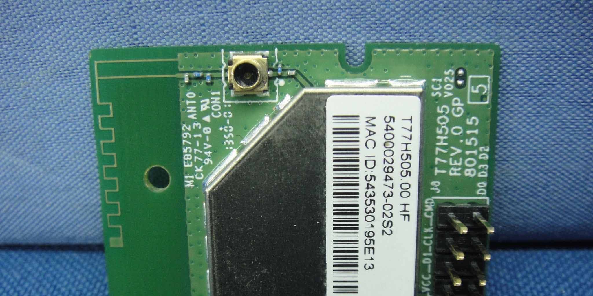
B3QT77H505
May 07, 2014IEEE802.11b/g/n Wi-Fi module
Equipment Class
DTS - Digital Transmission System