B3Q8VA652Label Printer
Brother Industries, Ltd.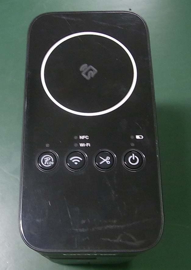
Click to zoom
Application Details
- Equipment Class
- DTS - Digital Transmission System
- Date of Grant
- Feb 01, 2014
- Application Purpose
- Original Equipment
- Date of Application
- Feb 01, 2014
- Equipment Note
- Label Printer
- Frequency Range
- 2412.00000000 - 2462.00000000
- Company
- Brother Industries, Ltd.
- Country
- Japan
Documents & Files
Document Text
Text extracted from the exhibit documents filed with the FCC. Open a document above to read the original.
Users Manual
Follow these guidelines to avoid the risk of fire, burns, injury, electric shocks, rupture, overheating, abnormal odors or smoke. • Always use the specified voltage and the included AC adapter (AD-E001) for the P-touch labeler to prevent any damage or failure. • Do not touch the P-touch labeler during a lightning storm. • Do not use the P-touch labeler/AC adapter in places of high humidity such as bathrooms. • Do not overload the power cord. • Do not place heavy objects on, or damage the P-touch labeler, power cord or plug. Do not forcibly bend or pull the power cord. Always hold the AC adapter when disconnecting from the power outlet. • Make sure that the plug is fully inserted in the power outlet. Do not use an outlet that is loose. • Do not allow the P-touch labeler/AC adapter/power plug/batteries to get wet, for example, by handling them with wet hands or spilling beverages on to them. • Do not disassemble or modify the P-touch labeler/AC adapter/batteries. • Do not allow a metal object to contact both the plus and minus ends of a battery. • Do not use sharp objects, such as tweezers or a metallic pen, to change the batteries. • Do not throw the batteries into fire or expose to heat. • Disconnect the AC adapter, remove batteries immediately and stop using the P-touch labeler if you notice abnormal odor, heat, discoloration, deformation or anything unusual while using or storing it. • Do not use a damaged or leaking battery as the fluid may get on your hands. • Do not use a deformed or leaking battery or one whose label is damaged. There is a possibility of damaging the P-touch labeler. • Since loss of eyesight may result if leaked fluid from batteries gets into your eyes, immediately rinse your eyes with a large amount of clean water, and then seek medical attention. Follow these guidelines to avoid personal injury, liquid leakage, burns or heat. • When the P-touch labeler is not being used, store it out of the reach of children. In addition, do not allow children to put any P-touch labeler parts or labels in their mouths. If any object has been swallowed, seek medical attention. • Do not touch metal parts around the print head immediately after printing. • Do not touch the cutter blade. (See Unpacking the PT-P750W & Parts Description.) • If leaked fluid from batteries gets on your skin or clothes, immediately rinse them with clean water. • Remove the batteries and disconnect the AC adapter if you do not intend to use the P-touch labeler. • Do not use any batteries other than those specified. Do not use combinations of old and new batteries or combinations of different types, different charging levels, different manufacturers or different models. Do not insert a battery with its plus and minus ends reversed. • Do not drop or hit the P-touch labeler/AC adapter. • Do not put your finger inside the P-touch labeler when you close the cassette cover. • Before using Ni-MH rechargeable batteries, carefully read the instructions for the batteries and battery charger, and be sure to use them correctly. • When using Ni-MH rechargeable batteries, charge the batteries with a specialized battery charger before using the batteries. • Do not put your finger inside the tape exit slot. You could be injured by the cutter blade. • Depending on the location, material, and environmental conditions, the label may unpeel or become irremovable, the color of the label may change or be transferred to other objects. Before applying the label, check the environmental conditions and the material. • Do not use the P-touch labeler in any way or for any purpose not described in this guide. Doing so may result in accidents or damage to the P-touch labeler. • Use only Brother TZe tapes with the P-touch labeler. Do not use tapes that do not have the mark. • Only use a soft, dry cloth to clean the P-touch labeler; never use alcohol or other organic solvents. • Use a soft wipe to clean the print head; never touch the print head with your fingers. • Do not put any foreign objects into the tape exit slot, the AC adapter connector or battery compartment, etc. • Do not place the P-touch labeler/batteries/AC adapter in direct sunlight or rain, near heaters or other hot appliances, in any location exposed to extremely high or low temperatures (e.g., on the dashboard or in the back of your car), high humidity, or in dusty locations. • Do not try to print if the cassette is empty; it will damage the print head. • Do not pull the tape while printing or feeding; it will damage the tape and the P-touch labeler. • Any data stored in memory will be lost due to failure or repair of the P-touch labeler, or if the batteries expire. • The P-touch labeler is not equipped with a charging feature for rechargeable batteries. • The length of the printed label may differ from the displayed label length on the computer. • A protective clear plastic sticker is placed over the top panel during manufacturing and shipping. This sticker should be removed prior to use. • When printing multiple copies of a label or using the numbering function printing, the P-touch labeler will not detect the end of the tape cassette and will continue operating. • When using Heat Shrink Tube, the printing area will be smaller than when using normal tape. • If you connect a mobile device to the P-touch labeler using the NFC function without installing a specialized application, the Apps section of Google Play may be displayed on your mobile device automatically. You may be charged a communication fee for this service. Open Source Licensing Remarks This product includes open-source software. To see the open source licensing remarks, please go to the manual download selection on your model's home page of Brother Solutions Center at http://solutions.brother.com/. The available scientific evidence does not show that any health problems are associated with using low power wireless devices. There is no proof, however, that these low power wireless devices are absolutely saf…
Text truncated - open the document above for the full version.
External Photos
Photo PT-P750W Photo PT-P750W Photo PT-P750W
Internal Photos
Photo PT-P750W Photo PT-P750W Photo PT-P750W
RF Exposure Info
Test report No. : 10154203H-C-R2 Page : 2 of 57 FCC ID : B3Q8VA652 Issued date : January 23, 2014 Revised date : January 31, 2014 UL Japan, Inc. Head Office EMC Lab. 4383-326 Asama-cho, Ise-shi, Mie-ken 516-0021 JAPAN Telephone: +81 596 24 8999 Facsimile: +81 596 24 8124 REVISION HISTORY Original Test Report No.: 10154203H-C Revision Test report No. Date Page revised Contents - (Original) 10154203H-C January 23, 2014 - - 1 10154203H-C-R1 January 28, 2014 P.4 Addition of note in Section 2.1. 2 10154203H-C-R2 January 31, 2014 P.8, P.11 Addition of the following sentences; The setting values on each mode are the approximate output values of when the EUT transmits in 100% ON period. The values of specifications are a time average values containing a transmitting OFF period. 2 10154203H-C-R2 January 31, 2014 P.13 Correction of the following 2 values in the table of Section 6.1 1); 1. Maximum tune-up tolerance limit 2. Min distance 2 10154203H-C-R2 January 31, 2014 P.14 Correction of the following 3 values in the table of Section 6.1 2); 1. Min distance 2. Maximum tune-up tolerance limit 3. Calculation of threshold Test report No. : 10154203H-C-R2 Page : 3 of 57 FCC ID : B3Q8VA652 Issued date : January 23, 2014 Revised date : January 31, 2014 UL Japan, Inc. Head Office EMC Lab. 4383-326 Asama-cho, Ise-shi, Mie-ken 516-0021 JAPAN Telephone: +81 596 24 8999 Facsimile: +81 596 24 8124 CONTENTS PAGE SECTION 1: Customer information .................................................................................................... 4 SECTION 2: Equipment under test (E.U.T.) ...................................................................................... 4 2.1 Identification of E.U.T. ....................................................................................................................................... 4 2.2 Product description ............................................................................................................................................. 4 SECTION 3 : Test standard information ............................................................................................ 5 3.1 Test Specification ............................................................................................................................................... 5 3.2 Procedure ............................................................................................................................................................ 5 3.3 Exposure limit .................................................................................................................................................... 6 3.4 Test Location ...................................................................................................................................................... 6 SECTION 4 : Test result ....................................................................................................................... 7 4.1 Stand-alone SAR result....................................................................................................................................... 7 SECTION 5 : Description of the operating mode ............................................................................... 8 5.1 Output power operating modes ........................................................................................................................... 8 5.2 Output power measurement results ..................................................................................................................... 9 5.3 SAR testing operating modes ............................................................................................................................. 11 5.4 Confirmation after SAR testing .......................................................................................................................... 12 SECTION 6 SAR test exclusion considerations .................................................................................. 13 6.1 Standalone SAR test exclusion considerations ................................................................................................... 13 SECTION 7: Description of the Body setup ........................................................................................ 15 7.1 Test position for Body setup ............................................................................................................................... 15 SECTION 8 : Test surrounding ........................................................................................................... 16 8.1 Measurement uncertainty ................................................................................................................................... 16 SECTION 9 : Measurement results ..................................................................................................... 17 9.1 WLAN Body SAR (2.4G) .................................................................................................................................. 17 SECTION 10 Test instruments ............................................................................................................. 18 APPENDIX 1 : SAR Measurement data ............................................................................................. 19 1. Evaluation procedure ................................................................................................................................. 19 2. Measurement data ...................................................................................................................................... 20 APPENDIX2 : System Validation ........................................................................................................ 26 1. System validation result Body 2450MHz .................................................................................................. 26 2. System Validation Dipole (D2450V2,S/N:713) ...…
Text truncated - open the document above for the full version.
Test Report
Test report No. : 10154203H-A-R2 Page : 2 of 45 Issued date : January 20, 2014 Revised date : January 28, 2014 FCC ID : B3Q8VA652 UL Japan, Inc. Head Office EMC Lab. 4383-326 Asama-cho, Ise-shi, Mie-ken 516-0021 JAPAN Telephone : +81 596 24 8999 Facsimile : +81 596 24 8124 REVISION HISTORY Original Test Report No.: 10154203H-A Revision Test report No. Date Page revised Contents - (Original) 10154203H-A January 20, 2014 - - 1 10154203H-A-R1 January 24, 2014 P.5 Addition of comment 1 10154203H-A-R1 January 24, 2014 P.11 Correction of sentence of Test Procedure 1 10154203H-A-R1 January 24, 2014 P.45 Addition of photos (Worst Case Position) 2 10154203H-A-R2 January 28, 2014 P.4 Addition of note in section 2.1 Test report No. : 10154203H-A-R2 Page : 3 of 45 Issued date : January 20, 2014 Revised date : January 28, 2014 FCC ID : B3Q8VA652 UL Japan, Inc. Head Office EMC Lab. 4383-326 Asama-cho, Ise-shi, Mie-ken 516-0021 JAPAN Telephone : +81 596 24 8999 Facsimile : +81 596 24 8124 CONTENTS PAGE SECTION 1: Customer information ......................................................................................................... 4 SECTION 2: Equipment under test (E.U.T.) ........................................................................................... 4 SECTION 3: Test specification, procedures & results ............................................................................ 5 SECTION 4: Operation of E.U.T. during testing .................................................................................... 8 SECTION 5: Conducted Emission .......................................................................................................... 10 SECTION 6: Radiated Spurious Emission ............................................................................................ 11 SECTION 7: Antenna Terminal Conducted Tests ................................................................................ 12 APPENDIX 1: Data of EMI test .............................................................................................................. 13 Conducted Emission ......................................................................................................................... 13 6dB Bandwidth ................................................................................................................................. 14 Maximum Peak Output Power .......................................................................................................... 17 Radiated Spurious Emission ............................................................................................................. 20 Conducted Spurious Emission .......................................................................................................... 31 Power Density ................................................................................................................................... 37 99%Occupied Bandwidth ................................................................................................................. 39 APPENDIX 2: Test instruments ............................................................................................................. 41 APPENDIX 3: Photographs of test setup ............................................................................................... 43 Conducted Emission ......................................................................................................................... 43 Radiated Spurious Emission ............................................................................................................. 44 Worst Case Position .......................................................................................................................... 45 Test report No. : 10154203H-A-R2 Page : 4 of 45 Issued date : January 20, 2014 Revised date : January 28, 2014 FCC ID : B3Q8VA652 UL Japan, Inc. Head Office EMC Lab. 4383-326 Asama-cho, Ise-shi, Mie-ken 516-0021 JAPAN Telephone : +81 596 24 8999 Facsimile : +81 596 24 8124 SECTION 1: Customer information Company Name : BROTHER INDUSTRIES, LTD. Address : 15-1, Naeshiro-cho, Mizuho-ku, Nagoya, Aihchi-ken, 467-8561 Japan Telephone Number : +81-52-824-2345 Facsimile Number : +81-52-821-1068 Contact Person : Shintaro Uno SECTION 2: Equipment under test (E.U.T.) 2.1 Identification of E.U.T. Type of Equipment : Label Printer Model No. : PT-P750W Serial No. : Refer to Section 4, Clause 4.2 Rating : DC12V, 2A, 24W AC 100-240V, 50/60Hz (AC Adaptor) * Test was performed with the EUT connected to AC Adaptor. Receipt Date of Sample : November 27, 2013 and December 13, 2013 Country of Mass-production : China Condition of EUT : Production prototype (Not for Sale: This sample is equivalent to mass-produced items.) Modification of EUT : No Modification by the test lab 2.2 Product Description General Specification Clock frequency(ies) in the system : CPU:96MHz Radio Specification Radio Type : Transceiver Frequency of Operation : 2412-2462MHz Modulation : DSSS Power Supply (radio part input) : DC 3.3V Antenna type : Internal Antenna Antenna Gain : 2.03dBi Test report No. : 10154203H-A-R2 Page : 5 of 45 Issued date : January 20, 2014 Revised date : January 28, 2014 FCC ID : B3Q8VA652 UL Japan, Inc. Head Office EMC Lab. 4383-326 Asama-cho, Ise-shi, Mie-ken 516-0021 JAPAN Telephone : +81 596 24 8999 Facsimile : +81 596 24 8124 SECTION 3: Test specification, procedures & results 3.1 Test Specification Test Specification : FCC Part 15 Subpart C: 2013, final revised on September 30, 2013 and effective October 30, 2013 Title : FCC 47CFR Part15 Radio Frequency Device Subpart C Intentional Radiators Section 15.207 Conducted limits Section 15.247 Operation within the bands 902-928MHz, 2400-2483.5MHz, and 5725-5850MHz * The EUT complies with FCC Part 15 Subpart B: 2013, final revised on September 30, 2013 and effective October 30, 2013. 3.2 Procedures and results Item Test Procedure Specification Worst…
Text truncated - open the document above for the full version.
Test Setup Photos
Test report No. : 10154203H-C-R2 Page : 54 of 57 FCC ID : B3Q8VA652 Issued date : January 23, 2014 Revised date : January 31, 2014 UL Japan, Inc. Head Office EMC Lab. 4383-326 Asama-cho, Ise-shi, Mie-ken 516-0021 JAPAN Telephone: +81 596 24 8999 Facsimile: +81 596 24 8124 APPENDIX 4: Photographs of test setup 1. Photographs of EUT Fron t Rea r Top Left Side Botto m Right Side Test report No. : 10154203H-C-R2 Page : 55 of 57 FCC ID : B3Q8VA652 Issued date : January 23, 2014 Revised date : January 31, 2014 UL Japan, Inc. Head Office EMC Lab. 4383-326 Asama-cho, Ise-shi, Mie-ken 516-0021 JAPAN Telephone: +81 596 24 8999 Facsimile: +81 596 24 8124 2. Antenna position Left side view Rea r view Test report No. : 10154203H-C-R2 Page : 56 of 57 FCC ID : B3Q8VA652 Issued date : January 23, 2014 Revised date : January 31, 2014 UL Japan, Inc. Head Office EMC Lab. 4383-326 Asama-cho, Ise-shi, Mie-ken 516-0021 JAPAN Telephone: +81 596 24 8999 Facsimile: +81 596 24 8124 3. Photographs of setup Front Test report No. : 10154203H-C-R2 Page : 57 of 57 FCC ID : B3Q8VA652 Issued date : January 23, 2014 Revised date : January 31, 2014 UL Japan, Inc. Head Office EMC Lab. 4383-326 Asama-cho, Ise-shi, Mie-ken 516-0021 JAPAN Telephone: +81 596 24 8999 Facsimile: +81 596 24 8124 Left side End of Report
Test Setup Photos
Test report No. : 10154203H-A-R2 Page : 43 of 45 Issued date : January 20, 2014 Revised date : January 28, 2014 FCC ID : B3Q8VA652 UL Japan, Inc. Head Office EMC Lab. 4383-326 Asama-cho, Ise-shi, Mie-ken 516-0021 JAPAN Telephone : +81 596 24 8999 Facsimile : +81 596 24 8124 APPENDIX 3: Photographs of test setup Conducted Emission Photo 1 Photo 2 Test report No. : 10154203H-A-R2 Page : 44 of 45 Issued date : January 20, 2014 Revised date : January 28, 2014 FCC ID : B3Q8VA652 UL Japan, Inc. Head Office EMC Lab. 4383-326 Asama-cho, Ise-shi, Mie-ken 516-0021 JAPAN Telephone : +81 596 24 8999 Facsimile : +81 596 24 8124 Radiated Spurious Emission Photo 1 Photo 2 Test report No. : 10154203H-A-R2 Page : 45 of 45 Issued date : January 20, 2014 Revised date : January 28, 2014 FCC ID : B3Q8VA652 UL Japan, Inc. Head Office EMC Lab. 4383-326 Asama-cho, Ise-shi, Mie-ken 516-0021 JAPAN Telephone : +81 596 24 8999 Facsimile : +81 596 24 8124 Worst Case Position (Horizontal: X-axis/ Vertical:X-axis) X-axis Y-axis Z-axis End of Report
Contact Information
Applicant
Masahiko Kimura
Technical Contact
UL Japan, Inc.Takahiro Hatakeda
[email protected]81-596-24-8999
4383-326 Asama-cho, Ise-shi · Mie-ken · Japan
Test Firm
UL Japan, Inc. Head office EMC Lab.Tetsuya Hashimoto
Technical Specifications
| # | Rule Parts | Frequency Range | Power Output |
|---|---|---|---|
| 1 | 15C | 2.41 GHz - 2.46 GHz | 221.80 mW |
Other Applications from Brother Industries, Ltd.
B3Q8VD101001
Oct 26, 2021Color Label Printer
Equipment Class
DTS - Digital Transmission System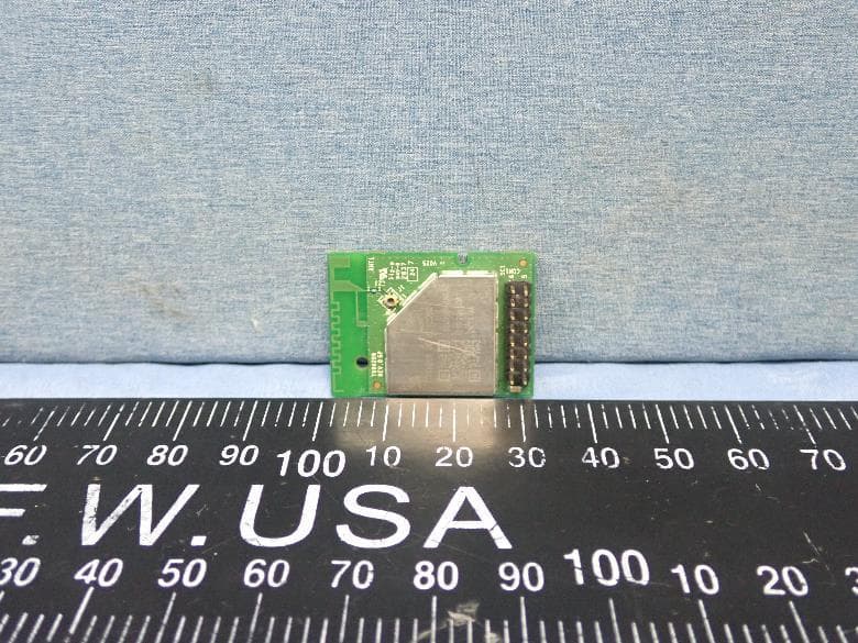
B3QT99H209
Mar 14, 2021IEEE802.11a/b/g/n/ac (1x1)+ BT 5.0 Combo Module
Equipment Class
DTS - Digital Transmission System
B3Q8V9313
Jul 09, 2015Mobile Printer
Equipment Class
DTS - Digital Transmission System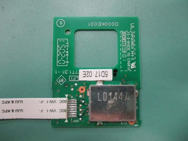
B3QBRNF13M002
Jul 06, 2015NFC Module
Equipment Class
DXX - Part 15 Low Power Communication Device Transmitter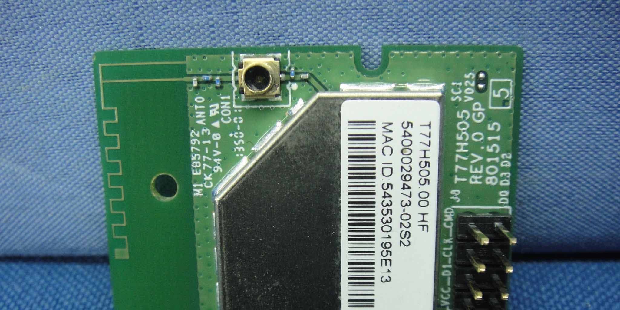
B3QT77H505
May 07, 2014IEEE802.11b/g/n Wi-Fi module
Equipment Class
DTS - Digital Transmission System