B3QBCLD10Digital Cordless Handset
Brother Industries, Ltd.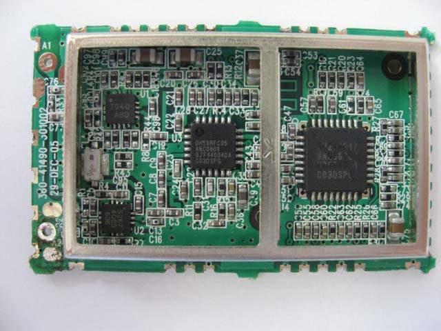
Click to zoom
Application Details
- Equipment Class
- DSS - Part 15 Spread Spectrum Transmitter
- Date of Grant
- Aug 17, 2006
- Application Purpose
- Original Equipment
- Date of Application
- Jul 10, 2006
- Equipment Note
- Digital Cordless Handset
- Frequency Range
- 5725.80000000 - 5848.90000000
- Company
- Brother Industries, Ltd.
- Country
- Japan
Documents & Files
Document Text
Text extracted from the exhibit documents filed with the FCC. Open a document above to read the original.
Users Manual
USER’S GUIDE Digital Cordless Handset i Brother numbers IMPORTANT For technical help, you must call the country where you bought the machine. Calls must be made from within that country. Register your product By registering your product with Brother International Corporation, you will be recorded as the original owner of the product. Your registration with Brother: may serve as confirmation of the purchase date of your product should you lose your receipt; may support an insurance claim by you in the event of product loss covered by insurance; and, will help us notify you of enhancements to your product and special offers. Please complete and fax the Brother Warranty Registration And Test Sheet or, for your convenience and most efficient way to register your new product, register on-line at http://www.brother.com/registration/ FAQs (frequently asked questions) The Brother Solutions Center is our one-stop resource for all your Fax Machine/Multi-Function Center needs. You can download the latest software documents and utilities, read FAQs and troubleshooting tips, and learn how to get the most from your Brother product. http://solutions.brother.com For Customer Service Service Center Locator (USA only) For the location of a Brother authorized service center, call 1-800-284-4357. Brother fax back system (USA only) Brother has installed an easy-to-use fax back system, so you can get instant answers to common technical questions and product information for all Brother products. This system is available 24 hours a day, 7 days a week. You can use the system to receive faxed instructions and an Index of fax back subjects. In USA:1-800-284-4329 (voice) 1-901-379-1215 (fax) 1-800-284-3238 (TTY service for the hearing-impaired) ii Ordering accessories and supplies For best quality results use only genuine Brother accessories, which are available at most Brother retailers. If you cannot find the accessory you need and you have a Visa, MasterCard, Discover, or American Express credit card, you can order accessories directly from Brother. (In the USA, you can visit us online for a complete selection of the Brother accessories and supplies that are available for purchase.) In USA only:1-800-521-2846 In USA:1-888-879-3232 (voice) 1-800-947-1445 (fax) http://www.brothermall.com DescriptionItem Cordless HandsetBCL-D10 BatteryBCL-BT10 User's Guidexxxxxxxx (English for USA and Canada) iii Notice - Disclaimer of Warranties (USA and Canada) BROTHER'S LICENSOR(S), AND THEIR DIRECTORS, OFFICERS, EMPLOYEES OR AGENTS (COLLECTIVELY BROTHER'S LICENSOR) MAKE NO WARRANTIES, EXPRESS OR IMPLIED, INCLUDING WITHOUT LIMITATION THE IMPLIED WARRANTIES OF MERCHANTABILITY AND FITNESS FOR A PARTICULAR PURPOSE, REGARDING THE SOFTWARE. BROTHER'S LICENSOR(S) DOES NOT WARRANT, GUARANTEE OR MAKE ANY REPRESENTATIONS REGARDING THE USE OR THE RESULTS OF THE USE OF THE SOFTWARE IN TERMS OF ITS CORRECTNESS, ACCURACY, RELIABILITY, CURRENTNESS OR OTHERWISE. THE ENTIRE RISK AS TO THE RESULTS AND PERFORMANCE OF THE SOFTWARE IS ASSUMED BY YOU. THE EXCLUSION OF IMPLIED WARRANTIES IS NOT PERMITTED BY SOME STATES IN THE USA AND SOME PROVINCES IN CANADA. THE ABOVE EXCLUSION MAY NOT APPLY TO YOU. IN NO EVENT WILL BROTHER'S LICENSOR(S) BE LIABLE TO YOU FOR ANY CONSEQUENTIAL, INCIDENTAL OR INDIRECT DAMAGES (INCLUDING DAMAGES FOR LOSS OF BUSINESS PROFITS, BUSINESS INTERRUPTION, LOSS OF BUSINESS INFORMATION, AND THE LIKE) ARISING OUT OF THE USE OR INABILITY TO USE THE SOFTWARE EVEN IF BROTHER'S LICENSOR HAS BEEN ADVISED OF THE POSSIBILITY OF SUCH DAMAGES. BECAUSE SOME STATES IN THE USA AND SOME PROVINCES IN CANADA DO NOT ALLOW THE EXCLUSION OR LIMITATION OF LIABILITY FOR CONSEQUENTIAL OR INCIDENTAL DAMAGES, THE ABOVE LIMITATIONS MAY NOT APPLY TO YOU. IN ANY EVENT BROTHER'S LICENSOR'S LIABILITY TO YOU FOR ACTUAL DAMAGES FROM ANY CAUSE WHATSOEVER, AND REGARDLESS OF THE FORM OF THE ACTION (WHETHER IN CONTRACT, TORT (INCLUDING NEGLIGENCE), PRODUCT LIABILITY OR OTHERWISE), WILL BE LIMITED TO $50. Compilation and Publication Notice Under the supervision of Brother Industries Ltd., this manual has been compiled and published, covering the latest product descriptions and specifications. The contents of this manual and the specifications of this product are subject to change without notice. Brother reserves the right to make changes without notice in the specifications and materials contained herein and shall not be responsible for any damages (including consequential) caused by reliance on the materials presented, including but not limited to typographical and other errors relating to the publication. iv Brother ® One Year Limited Warranty and Replacement Service (USA only) Who is covered: This limited warranty (“warranty”) is given only to the original end-use/retail purchaser (referred to in this warranty as “Original Purchaser”) of the accompanying product, consumables and accessories (collectively referred to in this warranty as “this Product”). If you purchased a product from someone other than an authorized Brother reseller in the United States or if the product was used (including but not limited to floor models or refurbished product), prior to your purchase you are not the Original Purchaser and the product that you purchased is not covered by this warranty. What is covered: This Product includes a Machine and Consumable and Accessory Items. Consumable and Accessory Items include but are not limited to print heads, toner, drums, ink cartridges, print cartridges, refill ribbons, therma PLUS paper and thermal paper. Except as otherwise provided herein, Brother warrants that the Machine and the accompanying Consumable and Accessory Items will be free from defects in materials and workmanship, when used under normal conditions. This warranty applies only to products purchased and used in the United States. For products purchased in, but used outside, the United States, this warranty covers only warranty service within the United States (and does…
Text truncated - open the document above for the full version.
Internal Photos
Internal Photo BROTHER INDUSTRIES,LTD. Digital Cordless Handset (Model: BCL-D10) FCC ID: B3QBCLD10 Antenna RF Module Over View RF Module Top (with cover) Internal Photo BROTHER INDUSTRIES,LTD. Digital Cordless Handset (Model: BCL-D10) FCC ID: B3QBCLD10 RF Module Bottom RF Module (cover off) 1 Internal Photo BROTHER INDUSTRIES,LTD. Digital Cordless Handset (Model: BCL-D10) FCC ID: B3QBCLD10 RF Module (cover off) 2
RF Exposure Info
Test report No. : 26KE0022-HO-B Page : 2 of 86 Issued date : July 11, 2006 FCC ID : B3QBCLD10 UL Apex Co., Ltd. Head Office EMC Lab. 4383-326 Asama-cho, Ise-shi, Mie-ken 516-0021 JAPAN Telephone : +81 596 24 8116 Facsimile : +81 596 24 8124 MF060a (01.06.05) CONTENTS PAGE SECTION 1 : Client information............................................................................................................................................ 3 SECTION 2 : Equipment under test (E.U.T.)........................................................................................................................ 3 2.1 Identification of E.U.T. ...................................................................................................................................... 3 2.2 Product description ............................................................................................................................................. 3 SECTION 3 : Test standard information............................................................................................................................... 5 3.1 Requirements for compliance testing defined by the FCC ................................................................................. 5 3.2 Exposure limit .................................................................................................................................................... 6 SECTION 4 : Test result ......................................................................................................................................................... 7 4.1 Result of Max. SAR value .................................................................................................................................. 7 4.2 Test Location ...................................................................................................................................................... 7 SECTION 5 : Operation of E.U.T. during testing................................................................................................................. 7 5.1 Operating modes................................................................................................................................................. 7 5.2 Description of the Head test setup ...................................................................................................................... 8 5.3 Description of the Body test setup...................................................................................................................... 10 5.4 Measurement procedure ..................................................................................................................................... 11 SECTION 6 : Test surrounding .............................................................................................................................................. 12 6.1 Measurement uncertainty ................................................................................................................................... 12 SECTION 7 : Confirmation before testing ............................................................................................................................ 13 7.1 Conducted power .................................................................................................................................................. 13 SECTION 8 : Measurement results........................................................................................................................................ 14 8.1 Head 5800MHz SAR.......................................................................................................................................... 14 8.2 Body-worn 5800MHz SAR ................................................................................................................................ 15 APPENDIX 1 : Photographs of test setup............................................................................................................................ 16 APPENDIX 2 : Test instruments.......................................................................................................................................... 32 Equipment & calibration information ..................................................................................................................... 33 1. Equipment used................................................................................................................................................... 33 2. Dosimetry assessment setup................................................................................................................................ 34 3. Configuration and peripherals............................................................................................................................. 35 4. System components ............................................................................................................................................ 36 5. Test system specifications................................................................................................................................... 38 6. Simulated Tissues Composition of 5GHz ........................................................................................................... 40 7. Validation Measurement ..................................................................................................................................... 40 8. System validation data ........................................................................................................................................ 41 9. Validation uncertainty......................................................................................................................................... 43 10. Validation Measurement data ............................................................................................…
Text truncated - open the document above for the full version.
RF Exposure Info
Test report No. : 26KE0022-HO-B Page : 32 of 86 Issued date : July 11, 2006 FCC ID : B3QBCLD10 UL Apex Co., Ltd. Head Office EMC Lab. 4383-326 Asama-cho, Ise-shi, Mie-ken 516-0021 JAPAN Telephone : +81 596 24 8116 Facsimile : +81 596 24 8124 MF060a (01.06.05) APPENDIX 2 : Test instruments Test report No. : 26KE0022-HO-B Page : 33 of 86 Issued date : July 11, 2006 FCC ID : B3QBCLD10 UL Apex Co., Ltd. Head Office EMC Lab. 4383-326 Asama-cho, Ise-shi, Mie-ken 516-0021 JAPAN Telephone : +81 596 24 8116 Facsimile : +81 596 24 8124 MF060a (01.06.05) Equipment & calibration information 1. Equipment used Control No. Instrument Manufacturer Model No Test Item Calibration Date * Interval(month) MPM-01 Power Meter Agilent E4417A SAR 2005/11/09 * 12 MPSE-01 Power Sensor Agilent E9300B SAR 2005/11/28 * 12 MPSE-03 Power sensor Agilent E9327A SAR 2005/11/23 * 12 MNA-01 Network Analyzer Agilent/HP E8358A SAR 2006/02/10 * 36 MSG-01 Signal Generator Rohde & Schwarz SMR40 SAR 2006/01/05 * 12 MRFA-08 Pre Amplifier TSJ TCBP0206 SAR 2006/03/11 * 12 MHDC-03 Dual Directional Coupler - Narda SAR Pre Check MPB-03 Dosimetric E-Field Probe Schmid&Partner Engineering AG EX3DV3 SAR 2006/05/26 * 12 MRBT-01 SAR measurement System Schmid&Partner Engineering AG DASY4 SAR Pre Check MDA-08 Dipole Antenna Schmid&Partner Engineering AG D5GHzV2 SAR 2004/02/23 * 24 MAT-15 Attenuator(30dB) Agilent US40010300 AT 2005/12/16 * 12 MRENT-38 Data Acquisition Electronics Schmid&Partner Engineering AG DAE3 SAR 2005/08/31 * 12 MSA-02 Spectrum Analyzer Advantest R3265A SAR Pre Check MOS-04 Digital Humidity Indicator N.T NT-1800 SAR 2004/11/25 * 24 Head 5800MHz - - - SAR Daily check Target value ± 5% Body 5800MHz - - - SAR Daily check Target value ± 5% SAR room - - - SAR Daily check Ambient1Noise< 0.012W/kg Test report No. : 26KE0022-HO-B Page : 34 of 86 Issued date : July 11, 2006 FCC ID : B3QBCLD10 UL Apex Co., Ltd. Head Office EMC Lab. 4383-326 Asama-cho, Ise-shi, Mie-ken 516-0021 JAPAN Telephone : +81 596 24 8116 Facsimile : +81 596 24 8124 MF060a (01.06.05) 2. Dosimetry assessment setup These measurements were performed with the automated near-field scanning system DASY4 from Schmid & Partner Engineering AG (SPEAG). The system is based on a high precision robot (working range greater than 0.9 m), which positions the probes with a positional repeatability of better than +/- 0.02 mm. Special E- and H-field probes have been developed for measurements close to material discontinuity, the sensors of which are directly loaded with a Schottky diode and connected via highly resistive lines to the data acquisition unit. The SAR measurements were conducted with the dosimetry probe EX3DV3, SN: 3507 (manufactured by SPEAG), designed in the classical triangular configuration and optimized for dosimetric evaluation. The probe has been calibrated according to the procedure described in [2] with accuracy of better than +/-10%. The spherical isotropy was evaluated with the procedure described in [3] and found to be better than +/-0.25 dB. The phantom used was the SAM Twin Phantom as described in FCC supplement C, IEEE P1528 and CENELEC EN50361. Test report No. : 26KE0022-HO-B Page : 35 of 86 Issued date : July 11, 2006 FCC ID : B3QBCLD10 UL Apex Co., Ltd. Head Office EMC Lab. 4383-326 Asama-cho, Ise-shi, Mie-ken 516-0021 JAPAN Telephone : +81 596 24 8116 Facsimile : +81 596 24 8124 MF060a (01.06.05) 3. Configuration and peripherals The DASY4 system for performing compliance tests consist of the following items: 1. A standard high precision 6-axis robot (Stäubli RX family) with controller and software. An arm extension for accommodating the data acquisition electronics (DAE). 2. A dosimetric probe, i.e., an isotropic E-field probe optimized and calibrated for usage in tissue simulating liquid. The probe is equipped with an optical surface detector system. 3. A data acquisition electronic (DAE), which performs the signal amplification, signal multiplexing, AD-conversion, offset measurements, mechanical surface detection, collision detection, etc. The unit is battery powered with standard or rechargeable batteries. The signal is optically transmitted to the EOC. 4. The Electro-optical converter (EOC) performs the conversion between optical and electrical of the signals for the digital communication to the DAE and for the analog signal from the optical surface detection. The EOC is connected to the measurement server. 5. The function of the measurement server is to perform the time critical tasks such as signal filtering, control of the robot operation and fast movement interrupts. 6. A probe alignment unit which improves the (absolute) accuracy of the probe positioning. 7. A computer operating Windows 2000. 8. DASY4 software. 9. Remote control with teaches pendant and additional circuitry for robot safety such as warning lamps, etc. 10. The SAM twin phantom enabling testing left-hand and right-hand usage. 11. The device holder for handheld mobile phones. 12. Tissue simulating liquid mixed according to the given recipes. 13. Validation dipole kits allowing to validate the proper functioning of the system. Test report No. : 26KE0022-HO-B Page : 36 of 86 Issued date : July 11, 2006 FCC ID : B3QBCLD10 UL Apex Co., Ltd. Head Office EMC Lab. 4383-326 Asama-cho, Ise-shi, Mie-ken 516-0021 JAPAN Telephone : +81 596 24 8116 Facsimile : +81 596 24 8124 MF060a (01.06.05) 4. System components 4.2.1 EX3DV3 Probe Specification 4.2.1 Probe Specification Construction: Symmetrical design with triangular core Built-in shielding against static charges PEEK enclosure material (resistant to organic solvents, e.g., glycol ether) Calibration (S/N3507): Basic Broad Band calibration in air : 10-3000 MHz Conversion Factors (Head and Body): 900 MHz, 1.8 GHz ,2.45GHz,5.2GHz and 5.8GHz(Head and Body) Frequency: 10 MHz to > 6GHz; Linearity: +/-0.2 dB(30 MHz to 3 GHz) Directivity: +/-0.3 dB in HSL (rotation around probe axis) +/-0.5 dB in tissue material (rotation normal probe axis) D…
Text truncated - open the document above for the full version.
RF Exposure Info
Test report No. : 26KE0022-HO-B Page : 67 of 86 Issued date : July 11, 2006 FCC ID : B3QBCLD10 UL Apex Co., Ltd. Head Office EMC Lab. 4383-326 Asama-cho, Ise-shi, Mie-ken 516-0021 JAPAN Telephone : +81 596 24 8116 Facsimile : +81 596 24 8124 MF060a (01.06.05) APPENDIX 3 : SAR Measurement data Test report No. : 26KE0022-HO-B Page : 68 of 86 Issued date : July 11, 2006 FCC ID : B3QBCLD10 UL Apex Co., Ltd. Head Office EMC Lab. 4383-326 Asama-cho, Ise-shi, Mie-ken 516-0021 JAPAN Telephone : +81 596 24 8116 Facsimile : +81 596 24 8124 MF060a (01.06.05) 1. Evaluation procedure The evaluation was performed with the following procedure: Step 1: Measurement of the E-field at a fixed location above the ear point or central position of flat phantom was used as a reference value for assessing the power drop. Step 2: The SAR distribution at the exposed side of head or body position was measured at a distance of each device from the inner surface of the shell. The area covered the entire dimension of the antenna of EUT and the horizontal grid spacing was 10 mm x 10 mm . Based on these data, the area of the maximum absorption was determined by spline interpolation. Step 3: Around this point found in the Step 2 (area scan) , a volume of 25.8mm x 25.8mm x 21mm was assessed by measuring 7 x 7 x 8 points. And for any secondary peaks found in the Step2 which are within 2dB of maximum peak and not with this Step3 (Zoom scan) is repeated. On the basis of this data set, the spatial peak SAR value was evaluated under the following procedure: (1). The data at the surface were extrapolated, since the center of the dipoles is 1mm away from the tip of the probe and the distance between the surface and the lowest measuring point is 1.3 mm. The extrapolation was based on a least square algorithm [4]. A polynomial of the fourth order was calculated through the points in z-axes. This polynomial was then used to evaluate the points between the surface and the probe tip. (2). The maximum interpolated value was searched with a straightforward algorithm. Around this maximum the SAR values averaged over the spatial volumes (1 g or 10 g) were computed by the 3D-Spline interpolation algorithm. The 3D-Spline is composed of three one-dimensional splines with the “Not a knot"-condition (in x, y and z-directions) [4], [5]. The volume was integrated with the trapezoidal-algorithm. One thousand points (10 x 10 x 10) were interpolated to calculate the average. (3). All neighboring volumes were evaluated until no neighboring volume with a higher average value was found. Step 4: Re-measurement of the E-field at the same location as in Step 1. Test report No. : 26KE0022-HO-B Page : 69 of 86 Issued date : July 11, 2006 FCC ID : B3QBCLD10 UL Apex Co., Ltd. Head Office EMC Lab. 4383-326 Asama-cho, Ise-shi, Mie-ken 516-0021 JAPAN Telephone : +81 596 24 8116 Facsimile : +81 596 24 8124 MF060a (01.06.05) 2. Measurement data BCL-D10 / Left head / Cheek position / 71ch (5788.240269MHz) Crest factor: 10 Medium parameters used: f = 5800 MHz; σ = 5.48 mho/m; ε r = 34.5; ρ = 1000 kg/m 3 Phantom section: Left Section Measurement Standard: DASY4 (High Precision Assessment) DASY4 Configuration: Probe: EX3DV3 - SN3507; ConvF(4.82, 4.82, 4.82); Calibrated: 2006/05/26 Sensor-Surface: 2mm (Mechanical Surface Detection) Electronics: DAE3 Sn518; Calibrated: 2005/08/31 Phantom: SAM 1196 Measurement SW: DASY4, V4.6 Build 23; Postprocessing SW: SEMCAD, V1.8 Build 160 Area Scan (101x101x1): Measurement grid: dx=10mm, dy=10mm Maximum value of SAR (interpolated) = 0.082 mW/g Zoom Scan (7x7x8)/Cube 0: Measurement grid: dx=4.3mm, dy=4.3mm, dz=3mm Reference Value = 2.21 V/m; Power Drift = -0.185 dB Peak SAR (extrapolated) = 0.400 W/kg SAR(1 g) = 0.042 mW/g; SAR(10 g) = 0.013 mW/g Maximum value of SAR (measured) = 0.080 mW/g Test Date = 07/04/06 Ambient Temperature = 24.2 degree C. Liquid Temperature = Before 24.0 degree C. , After 24.0 degree C. Test report No. : 26KE0022-HO-B Page : 70 of 86 Issued date : July 11, 2006 FCC ID : B3QBCLD10 UL Apex Co., Ltd. Head Office EMC Lab. 4383-326 Asama-cho, Ise-shi, Mie-ken 516-0021 JAPAN Telephone : +81 596 24 8116 Facsimile : +81 596 24 8124 MF060a (01.06.05) BCL-D10 / Left head / Tilt position / 71ch (5788.240269MHz) Crest factor: 10 Medium parameters used: f = 5800 MHz; σ = 5.48 mho/m; ε r = 34.5; ρ = 1000 kg/m 3 Phantom section: Left Section Measurement Standard: DASY4 (High Precision Assessment) DASY4 Configuration: Probe: EX3DV3 - SN3507; ConvF(4.82, 4.82, 4.82); Calibrated: 2006/05/26 Sensor-Surface: 2mm (Mechanical Surface Detection) Electronics: DAE3 Sn518; Calibrated: 2005/08/31 Phantom: SAM 1196 Measurement SW: DASY4, V4.6 Build 23; Postprocessing SW: SEMCAD, V1.8 Build 160 Area Scan (101x101x1): Measurement grid: dx=10mm, dy=10mm Maximum value of SAR (interpolated) = 0.122 mW/g Zoom Scan (7x7x8)/Cube 0: Measurement grid: dx=4.3mm, dy=4.3mm, dz=3mm Reference Value = 0.711 V/m; Power Drift = -0.030 dB Peak SAR (extrapolated) = 0.168 W/kg SAR(1 g) = 0.046 mW/g; SAR(10 g) = 0.014 mW/g Maximum value of SAR (measured) = 0.094 mW/g Test Date = 07/04/06 Ambient Temperature = 24.2 degree C. Liquid Temperature = Before 24.0 degree C. , After 24.0 degree C. Test report No. : 26KE0022-HO-B Page : 71 of 86 Issued date : July 11, 2006 FCC ID : B3QBCLD10 UL Apex Co., Ltd. Head Office EMC Lab. 4383-326 Asama-cho, Ise-shi, Mie-ken 516-0021 JAPAN Telephone : +81 596 24 8116 Facsimile : +81 596 24 8124 MF060a (01.06.05) BCL-D10 / Right head / Cheek position / 71ch (5788.240269MHz) Crest factor: 10 Medium parameters used: f = 5800 MHz; σ = 5.48 mho/m; ε r = 34.5; ρ = 1000 kg/m 3 Phantom section: Right Section Measurement Standard: DASY4 (High Precision Assessment) DASY4 Configuration: Probe: EX3DV3 - SN3507; ConvF(4.82, 4.82, 4.82); Calibrated: 2006/05/26 Sensor-Surface: 2mm (Mechanical Surface Detection) Electronics: DAE3 Sn518; Calibrated: 2005/08/31 Phantom: SAM 1196 Measurement SW: DASY4, V4.6 Build 23; Postprocessing SW: SEMCAD…
Text truncated - open the document above for the full version.
Test Report
Test report No. : 26KE0022-HO-A Page : 1 of 37 Issued date : July 11, 2006 FCC ID : B3QBCLD10 UL Apex Co., Ltd. Head Office EMC Lab. 4383-326 Asama-cho, Ise-shi, Mie-ken 516-0021 JAPAN Telephone : +81 596 24 8116 Facsimile : +81 596 24 8124 MF060b(24.05.06) RADIO TEST REPORT Test Report No. : 26KE0022-HO-A Applicant : BROTHER INDUSTRIES, LTD. Type of Equipment : Digital Cordless Handset Model No. : BCL-D10 FCC ID : B3QBCLD10 Test standard : FCC Part 15 Subpart C Section 15.207, Section 15.247: 2006 Test Result : Complied 1. This test report shall not be reproduced in full or partial, without the written approval of UL Apex Co., Ltd. 2. The results in this report apply only to the sample tested. 3. This equipment is in compliance with the above regulation. 4. The test results in this report are traceable to the national or international standards. Date of test: _____________________________ Tested by: _____________________________ _____________________________ Makoto Kosaka EMC Services Mitsuru Fujimura EMC Services _____________________________ Yutaka Yoshida EMC Services Approved by : ______________________________ Tetsuo Maeno Site Manager of EMC Services June 30 to July 10, 2006 NVLAP LAB CODE: 200572-0 This laboratory is accredited by the NVLAP LAB CODE 200572-0, U.S.A. The tests reported herein have been performed in accordance with its terms of accreditation. *As for the range of Accreditation in NVLAP, you may refer to the WEB address, http://ulapex.jp/emc/nvlap.htm Test report No. : 26KE0022-HO-A Page : 2 of 37 Issued date : July 11, 2006 FCC ID : B3QBCLD10 UL Apex Co., Ltd. Head Office EMC Lab. 4383-326 Asama-cho, Ise-shi, Mie-ken 516-0021 JAPAN Telephone : +81 596 24 8116 Facsimile : +81 596 24 8124 MF060b(24.05.06) CONTENTS PAGE SECTION 1: Client information ............................................................................................................ 3 SECTION 2: Equipment under test (E.U.T.)........................................................................................ 3 SECTION 3: Test specification, procedures & results......................................................................... 4 SECTION 4: Operation of E.U.T. during testing .................................................................................7 SECTION 5: Conducted Emission......................................................................................................... 8 SECTION 6: Spurious Emission ............................................................................................................ 9 SECTION 7: Bandwidth ......................................................................................................................... 9 SECTION 8: Maximum Peak Output Power ..................................................................................... 10 SECTION 9: Carrier Frequency Separation ...................................................................................... 10 SECTION 10: Number of Hopping Frequency .................................................................................. 10 SECTION 11: Dwell time...................................................................................................................... 10 APPENDIX 1: Photographs of test setup ............................................................................................ 11 Conducted emission ................................................................................................................................ 11 Spurious Emission (Radiated) ............................................................................................................... 12 Worst Case Position (Horizontal: Z-axis/ Vertical:Y-axis)................................................................. 13 APPENDIX 2: Test instruments .......................................................................................................... 14 APPENDIX 3: Data of EMI test........................................................................................................... 15 Conducted Emission ............................................................................................................................... 15 Carrier Frequency Separation .............................................................................................................. 16 20dB Bandwidth ..................................................................................................................................... 18 Number of Hopping Frequency............................................................................................................. 20 Dwell time................................................................................................................................................ 22 Maximum Peak Output Power.............................................................................................................. 24 Radiated Spurious Emission.................................................................................................................. 25 Conducted Spurious Emission............................................................................................................... 31 Test report No. : 26KE0022-HO-A Page : 3 of 37 Issued date : July 11, 2006 FCC ID : B3QBCLD10 UL Apex Co., Ltd. Head Office EMC Lab. 4383-326 Asama-cho, Ise-shi, Mie-ken 516-0021 JAPAN Telephone : +81 596 24 8116 Facsimile : +81 596 24 8124 MF060b(24.05.06) SECTION 1: Client information Company Name BROTHER INDUSTRIES,LTD. Brand name b…
Text truncated - open the document above for the full version.
Contact Information
Applicant
Masahiko Kimura
Technical Contact
UL Apex Co., Ltd.Tetsuo Maeno
[email protected]+81-596-24-8116
4383-326 Asama-cho, · Ise-shi, Mie-ken · Japan
Non-Technical Contact
UL Apex Co., Ltd.Yoshinobu Asai
[email protected]+81-596-24-8116
Test Firm
UL Japan, Inc. Yokowa EMC Lab.Masamichi Ishii
Technical Specifications
| # | Rule Parts | Frequency Range | Power Output |
|---|---|---|---|
| 1 | 15C | 5.73 GHz - 5.85 GHz | 78.30 mW |
Other Applications from Brother Industries, Ltd.
B3Q8VD101001
Oct 26, 2021Color Label Printer
Equipment Class
DTS - Digital Transmission System
B3QT99H209
Mar 14, 2021IEEE802.11a/b/g/n/ac (1x1)+ BT 5.0 Combo Module
Equipment Class
DTS - Digital Transmission System
B3Q8V9313
Jul 09, 2015Mobile Printer
Equipment Class
DTS - Digital Transmission System
B3QBRNF13M002
Jul 06, 2015NFC Module
Equipment Class
DXX - Part 15 Low Power Communication Device Transmitter
B3QT77H505
May 07, 2014IEEE802.11b/g/n Wi-Fi module
Equipment Class
DTS - Digital Transmission System