B3QBCLD10ADigital Cordless Handset
Brother Industries, Ltd.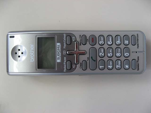
Click to zoom
Application Details
- Equipment Class
- DSS - Part 15 Spread Spectrum Transmitter
- Date of Grant
- Mar 08, 2007
- Application Purpose
- Original Equipment
- Date of Application
- Mar 07, 2007
- Equipment Note
- Digital Cordless Handset
- Frequency Range
- 5725.80900000 - 5848.88900000
- Company
- Brother Industries, Ltd.
- Country
- Japan
Documents & Files
Document Text
Text extracted from the exhibit documents filed with the FCC. Open a document above to read the original.
Users Manual
USER’S GUIDE Digital Cordless Handset BCL-D10 © 2006 Brother Industries, Ltd. i Brother numbers IMPORTANT For technical help, you must call the country where you bought the machine/cordless handset. Calls must be made from within that country. FAQs (frequently asked questions) The Brother Solutions Center is our one-stop resource for all your Fax Machine/Multi-Function Center needs. You can download the latest software documents and utilities, read FAQs and troubleshooting tips, and learn how to get the most from your Brother product. http://solutions.brother.com For Customer Service Service Center Locator (USA only) For the location of a Brother authorized service center, call 1-800-284-4357. In USA:1-800-284-4329 (voice) 1-901-379-1215 (fax) 1-800-284-3238 (TTY service for the hearing-impaired) ii Ordering accessories and supplies For best quality results use only genuine Brother accessories, which are available at most Brother retailers. If you cannot find the accessory you need and you have a Visa, MasterCard, Discover, or American Express credit card, you can order accessories directly from Brother. (In the USA, you can visit us online for a complete selection of the Brother accessories and supplies that are available for purchase.) Compilation and Publication Notice Under the supervision of Brother Industries Ltd., this manual has been compiled and published, covering the latest product descriptions and specifications. The contents of this manual and the specifications of this product are subject to change without notice. Brother reserves the right to make changes without notice in the specifications and materials contained herein and shall not be responsible for any damages (including consequential) caused by reliance on the materials presented, including but not limited to typographical and other errors relating to the publication. In USA:1-888-879-3232 (voice) 1-800-947-1445 (fax) http://www.brothermall.com DescriptionItem Cordless HandsetBCL-D10 BatteryBCL-BT10 User’s GuideLP5403001 iii Brother ® One Year Limited Warranty and Replacement Service (USA only) Who is covered: This limited warranty (“warranty”) is given only to the original end-use/retail purchaser (referred to in this warranty as “Original Purchaser”) of the accompanying product, consumables and accessories (collectively referred to in this warranty as “this Product”). If you purchased a product from someone other than an authorized Brother reseller in the United States or if the product was used (including but not limited to floor models or refurbished product), prior to your purchase you are not the Original Purchaser and the product that you purchased is not covered by this warranty. What is covered: This Product includes a battery, Except as otherwise provided herein, Brother warrants that the Product and battery will be free from defects in materials and workmanship, when used under normal conditions. This warranty applies only to products purchased and used in the United States. For products purchased in, but used outside, the United States, this warranty covers only warranty service within the United States (and does not include shipping outside the United States). What is the length of the Warranty Periods: Product: one year from the original purchase date. Battery: 90 days from the original purchase date or the rated life, whichever comes first. What is NOT covered: This warranty does not cover: 1 Physical damage or normal wear and tear to this Product; 2 Damage caused by improper installation, improper or abnormal use, misuse, neglect or accident (including but not limited to transporting this Product without the proper preparation and/or packaging); 3 Damage caused by another device, power surges or lightening; 4 Conditions beyond the control of Brother, such as common carrier provided services, and 5 Problems arising from other than defects in materials or workmanship. This limited warranty is VOID if this Product has been altered or modified in any way (including but not limited to attempted warranty repair without authorization from Brother and/or alteration/removal of the serial number). What to do if you think your Product is eligible for warranty service: Report your issue to our Customer Service Hotline at 1-800-284-4329 Supply Brother with a copy of your dated bill of sale showing that this Product was purchased within the U.S What Brother will ask you to do: After contacting Brother you may be required to deliver (by hand if you prefer) or send the Product properly packaged, freight prepaid, to the Brother Service Center together with a photocopy of your bill of sale. You are responsible for the cost of shipping, packing product, and insurance (if you desire). You are also responsible for loss or damage to this Product in shipping. What Brother will do: If the problem reported concerning your Product is covered by this warranty and if you first reported the problem to Brother within the applicable warranty period, Brother will repair or replace the Product at no charge to you for parts or labor. The decision as to whether to repair or replace the Product is made by Brother in its sole discretion. Brother reserves the right to supply a refurbished or remanufactured replacement Product and use refurbished parts provided such replacement products conform to the manufacturer’s specifications for new product/parts. The repaired or replacement Product will be returned to you freight prepaid or made available for you to pick up at the Brother Service Center. iv Brother ® One Year Limited Warranty and Replacement Service (USA only) If the Product is not covered by this warranty (either stage), you will be charged for shipping the Product back to you and charged for any service and/or replacement parts/products at Brother's then current published rates. The foregoing are your sole (i.e., only) and exclusive remedies under this warranty. What happens when Brother elects to replace your Product: Whe…
Text truncated - open the document above for the full version.
Cover Letter(s)
American Telecommunications Certification Body Inc. 6731 Whittier Ave, McLean, VA 22101 March 6, 2007 RE: FCC ID: B3QBCLD10A_ATCB004604 Attention: I have a few comments on this Application. Please note that further comments may arise in response to answers provided to the questions below. 1. Please note that the device appears to operate in the 5.7GHz frequency range. Please explain why the bandwidth data table listed on page 4 of the data portion of the report states 2402- 2480MHz. Please correct as necessary. 2. Please note that the latest interpretation from the FCC concerning placement of the 2-condition statement is “If the labelling area for the device is so small, or it is not practical to place the required statement on the device, then the statement can be placed in the user manual or product packaging - Section 15.19(a)(5). Generally, devices smaller than the palm of the hand are considered small.” While the device may be handheld it is appears to be larger than the palm. This then brings into question the validity of placing the 2-condition statement in the manual and not on the device. Please justify why the statement is not on the label. Dennis Ward mailto:[email protected] The items indicated above must be submitted before processing can continue on the above referenced application. Failure to provide the requested information may result in application termination. Correspondence should be considered part of the permanent submission and may be viewed from the Internet after a Grant of Equipment Authorization is issued. Please do not respond to this correspondence using the email reply button. In order for your response to be processed expeditiously, you must submit your documents through the AmericanTCB.com website. Also, please note that partial responses increase processing time and should not be submitted. Any questions about the content of this correspondence should be directed to the sender.
Cover Letter(s)
Dward ATCB From: [email protected] Sent: 03/07/2007 1:40 AM To: [email protected] Cc: [email protected]; [email protected] Subject: Re: B3QBCLD10A_ATCB004604 03/08/07 Dear Dennis-san, Thank you very much for your comment. Regarding your comments, please accept our answer as follows; 1.We're sorry it's a typing error. We uploaded the corrected FCC/IC test report, please confirm it. 2. The Sentences " 2- condition statement"cannot be displayed because the size of letter is small. Users can't confirm easily if we place it on label. We applied the similar product( the difference is only outpower) to FCC directly before and FCC accepted it. So could you please accept it? As reference, we will tell you FCC ID of the product. Please confirm it. FCC ID:B3QBCLD10 We truly appreciate for your cooperation. Best Regards UL Apex Co.Ltd. Yoshinobu Asai 4383-326 Asama-cho Ise-shi Mie-ken 516-0021 Application Section, EMC Services Division TEL:0596-24-8116 / FAX:0596-24-8095 E-mail:[email protected] Home Page:www.ulapex.jp "Dward ATCB" <[email protected]> 2007/03/07 09:42 To <[email protected]>, <[email protected]> cc SubjectB3QBCLD10A_ATCB004604 HI Hironobu / Yoshinobu Please see comments Thanks Dennis Ward Evaluation Engineer American TCB Certification Resource for the Wireless Industry www.atcb.com 703-847-4700 fax 703-847-6888 direct - 703-880-4841 cell - 209-769-8316 NOTICE: This E-Mail message and any attachment may contain privileged or company proprietary information. If you received this message in error, please return to the sender. [attachment "3-6-07 B3QBCLD10A_ATCB Comments.pdf" deleted by Yoshinobu Asai/ISE/ULI] - For more information about UL, its Marks, and its services for EMC, quality registrations and product certifications for global markets, please access our web sites at http://www.ul.com and http://www.ul-asia.com or contact your local sales representative. -- ********* Internet E-mail Confidentiality Disclaimer ********** This e-mail message may contain privileged or confidential information. If you are not the intended recipient, you may not disclose, use, disseminate, distribute, copy or rely upon this message or attachment in any way. If you received this e-mail message in error, please return by forwarding the message and its attachments to the sender. UL and its affiliates do not accept liability for any errors, omissions, corruption or virus in the contents of this message or any attachments. ***************************************************************** Please respond to <[email protected]> 03/08/07
External Photos
External Photo Brother Industries, Ltd. Digital Cordless Handset (Model: BCL-D10) FCC ID: B3QBCLD10A IC: 1112C- BCLD10A Top Bottom External Photo Brother Industries, Ltd. Digital Cordless Handset (Model: BCL-D10) FCC ID: B3QBCLD10A IC: 1112C- BCLD10A Front Back External Photo Brother Industries, Ltd. Digital Cordless Handset (Model: BCL-D10) FCC ID: B3QBCLD10A IC: 1112C- BCLD10A Side 1 Side 2
Internal Photos
Internal Photo Brother Industries, Ltd. Digital Cordless Handset (Model: BCL-D10) FCC ID: B3QBCLD10A IC: 1112C- BCLD10A RF Module Antenna Over View RF Module Top (with cover) Internal Photo Brother Industries, Ltd. Digital Cordless Handset (Model: BCL-D10) FCC ID: B3QBCLD10A IC: 1112C- BCLD10A RF Module Bottom RF Module (cover off) 1 Internal Photo Brother Industries, Ltd. Digital Cordless Handset (Model: BCL-D10) FCC ID: B3QBCLD10A IC: 1112C- BCLD10A RF Module (cover off) 2
RF Exposure Info
Test report No. : 27GE0058-HO-C-1 Page : 2 of 67 FCC ID : B3QBCLD10A Issued date : February 26, 2007 Revised date : February 27, 2007 UL Apex Co., Ltd. Head Office EMC Lab. 4383-326 Asama-cho, Ise-shi, Mie-ken 516-0021 JAPAN Telephone: +81 596 24 8116 Facsimile: +81 596 24 8124 CONTENTS PAGE SECTION 1: Client information............................................................................................................................................. 3 SECTION 2: Equipment under test (E.U.T.)......................................................................................................................... 3 2.2 Product description ............................................................................................................................................. 4 SECTION 3 : Test standard information............................................................................................................................... 5 3.1 Requirements for compliance testing defined by the FCC ................................................................................. 5 3.2 Exposure limit .................................................................................................................................................... 6 SECTION 4 : Test result ......................................................................................................................................................... 7 4.1 Result of Max. SAR value .................................................................................................................................. 7 4.2 Test Location ...................................................................................................................................................... 7 SECTION 5 : Operation of E.U.T. during testing................................................................................................................. 8 5.1 Confirmation before SAR testing ....................................................................................................................... 8 5.2 Confirmation after SAR testing .......................................................................................................................... 8 5.3 Operating modes for SAR testing ....................................................................................................................... 8 5.2 Description of the head test setup ....................................................................................................................... 9 5.3 Method of measurement (Head SAR) ................................................................................................................ 10 5.4 Description of the Body-worn test setup and Method ........................................................................................ 10 SECTION 6 : Test surrounding.............................................................................................................................................. 11 6.1 Measurement uncertainty ................................................................................................................................... 11 SECTION 7 : Confirmation before/after testing ................................................................................................................... 12 7.1 Conducted power before..................................................................................................................................... 12 SECTION 8 : Measurement results........................................................................................................................................ 13 8.1 Head 5800MHz SAR.......................................................................................................................................... 13 8.2 Body-worn 5800MHz SAR ................................................................................................................................ 14 APPENDIX 1 : Photographs of test setup............................................................................................................................ 15 APPENDIX 2 : SAR Measurement data.............................................................................................................................. 23 1. Evaluation procedure .......................................................................................................................................... 24 2. Measurement data (Head SAR) .......................................................................................................................... 25 3. Measurement data (Body-worn SAR)................................................................................................................. 31 APPENDIX 3 : Test instruments.......................................................................................................................................... 35 1. Equipment used................................................................................................................................................... 36 2. Dosimetry assessment setup................................................................................................................................ 37 3. Configuration and peripherals............................................................................................................................. 38 4. System components ............................................................................................................................................ 39 5. Test system specifications................................................................................................................................... 41 6. Simulated Tissues Composition of 5GHz ........................................................................................................... 42 7. Valid…
Text truncated - open the document above for the full version.
RF Exposure Info
Test report No. : 27GE0058-HO-C-1 Page : 23 of 67 FCC ID : B3QBCLD10A Issued date : February 26, 2007 Revised date : February 27, 2007 UL Apex Co., Ltd. Head Office EMC Lab. 4383-326 Asama-cho, Ise-shi, Mie-ken 516-0021 JAPAN Telephone: +81 596 24 8116 Facsimile: +81 596 24 8124 APPENDIX 2 : SAR Measurement data Test report No. : 27GE0058-HO-C-1 Page : 24 of 67 FCC ID : B3QBCLD10A Issued date : February 26, 2007 Revised date : February 27, 2007 UL Apex Co., Ltd. Head Office EMC Lab. 4383-326 Asama-cho, Ise-shi, Mie-ken 516-0021 JAPAN Telephone: +81 596 24 8116 Facsimile: +81 596 24 8124 1. Evaluation procedure The evaluation was performed with the following procedure: Step 1: Measurement of the E-field at a fixed location above the ear point or central position of flat phantom was used as a reference value for assessing the power drop. Step 2: The SAR distribution at the exposed side of head or body position was measured at a distance of each device from the inner surface of the shell. The area covered the entire dimension of the antenna of EUT and the horizontal grid spacing was 10 mm x 10 mm . Based on these data, the area of the maximum absorption was determined by spline interpolation. Step 3: Around this point found in the Step 2 (area scan) , a volume of 24mm x 24mm x 20mm was assessed by measuring 7 x 7 x 11 points. And for any secondary peaks found in the Step2 which are within 2dB of maximum peak (level more than ambient noise (> 0.012 W/kg)) and not with this Step3 (Zoom scan) is repeated. On the basis of this data set, the spatial peak SAR value was evaluated under the following procedure: (1). The data at the surface were extrapolated, since the center of the dipoles is 1mm away from the tip of the probe and the distance between the surface and the lowest measuring point is 1.3 mm. The extrapolation was based on a least square algorithm [4]. A polynomial of the fourth order was calculated through the points in z-axes. This polynomial was then used to evaluate the points between the surface and the probe tip. (2). The maximum interpolated value was searched with a straightforward algorithm. Around this maximum the SAR values averaged over the spatial volumes (1 g or 10 g) were computed by the 3D-Spline interpolation algorithm. The 3D-Spline is composed of three one-dimensional splines with the “Not a knot"-condition (in x, y and z-directions) [4], [5]. The volume was integrated with the trapezoidal-algorithm. One thousand points (10 x 10 x 10) were interpolated to calculate the average. (3). All neighboring volumes were evaluated until no neighboring volume with a higher average value was found. Step 4: Re-measurement of the E-field at the same location as in Step 1. Test report No. : 27GE0058-HO-C-1 Page : 25 of 67 FCC ID : B3QBCLD10A Issued date : February 26, 2007 Revised date : February 27, 2007 UL Apex Co., Ltd. Head Office EMC Lab. 4383-326 Asama-cho, Ise-shi, Mie-ken 516-0021 JAPAN Telephone: +81 596 24 8116 Facsimile: +81 596 24 8124 2. Measurement data (Head SAR) BCL-D10/ Left Head / Cheek / 71ch(5788.240269MHz) Crest factor: 9.5 Medium parameters used: f = 5800 MHz; σ = 5.2 mho/m; ε r = 32.1; ρ = 1000 kg/m 3 Phantom section: Left Section Measurement Standard: DASY4 (High Precision Assessment) DASY4 Configuration: Probe: EX3DV3 - SN3507; ConvF(4.82, 4.82, 4.82); Calibrated: 2006/05/26 Sensor-Surface: 2mm (Mechanical Surface Detection) Electronics: DAE3 Sn509; Calibrated: 2006/06/15 Phantom: SAM 1196 Measurement SW: DASY4, V4.6 Build 23; Postprocessing SW: SEMCAD, V1.8 Build 160 Area Scan (101x101x1): Measurement grid: dx=10mm, dy=10mm Maximum value of SAR (interpolated) = 0.107 mW/g Zoom Scan (7x7x11)/Cube 0: Measurement grid: dx=4mm, dy=4mm, dz=2mm Reference Value = 3.89 V/m; Power Drift = -0.203 dB Peak SAR (extrapolated) = 0.183 W/kg SAR(1 g) = 0.048 mW/g; SAR(10 g) = 0.014 mW/g Maximum value of SAR (measured) = 0.100 mW/g Test Date = 02/15/07 Ambient Temperature = 25.0degree C. Liquid Temperature = Before 22.8 degree C. , After 22.8 degree C. Test report No. : 27GE0058-HO-C-1 Page : 26 of 67 FCC ID : B3QBCLD10A Issued date : February 26, 2007 Revised date : February 27, 2007 UL Apex Co., Ltd. Head Office EMC Lab. 4383-326 Asama-cho, Ise-shi, Mie-ken 516-0021 JAPAN Telephone: +81 596 24 8116 Facsimile: +81 596 24 8124 BCL-D10/ Left Head / Tilt / 71ch(5788.240269MHz) Crest factor: 9.5 Medium parameters used: f = 5800 MHz; σ = 5.2 mho/m; ε r = 32.1; ρ = 1000 kg/m 3 Phantom section: Left Section Measurement Standard: DASY4 (High Precision Assessment) DASY4 Configuration: Probe: EX3DV3 - SN3507; ConvF(4.82, 4.82, 4.82); Calibrated: 2006/05/26 Sensor-Surface: 2mm (Mechanical Surface Detection) Electronics: DAE3 Sn509; Calibrated: 2006/06/15 Phantom: SAM 1196 Measurement SW: DASY4, V4.6 Build 23; Postprocessing SW: SEMCAD, V1.8 Build 160 Area Scan (81x81x1): Measurement grid: dx=10mm, dy=10mm Maximum value of SAR (interpolated) = 0.133 mW/g Zoom Scan (7x7x11)/Cube 0: Measurement grid: dx=4mm, dy=4mm, dz=2mm Reference Value = 3.98 V/m; Power Drift = 0.202 dB Peak SAR (extrapolated) = 0.179 W/kg SAR(1 g) = 0.047 mW/g; SAR(10 g) = 0.013 mW/g Maximum value of SAR (measured) = 0.100 mW/g Test Date = 02/15/07 Ambient Temperature = 24.5degree C. Liquid Temperature = Before 22.8 degree C. , After 22.8 degree C. Test report No. : 27GE0058-HO-C-1 Page : 27 of 67 FCC ID : B3QBCLD10A Issued date : February 26, 2007 Revised date : February 27, 2007 UL Apex Co., Ltd. Head Office EMC Lab. 4383-326 Asama-cho, Ise-shi, Mie-ken 516-0021 JAPAN Telephone: +81 596 24 8116 Facsimile: +81 596 24 8124 BCL-D10/ Right Head / Cheek / 71ch(5788.240269MHz) Crest factor: 9.5 Medium parameters used: f = 5800 MHz; σ = 5.2 mho/m; ε r = 32.1; ρ = 1000 kg/m 3 Phantom section: Right Section Measurement Standard: DASY4 (High Precision Assessment) DASY4 Configuration: Probe: EX3DV3 - SN3507; ConvF(4.82, 4.82, 4.82); Calibrated: 2006/05/26 Sensor-Surface: 2mm (Mechanical Surface Detection) Electronics: DAE3 S…
Text truncated - open the document above for the full version.
RF Exposure Info
Test report No. : 27GE0058-HO-C-1 Page : 35 of 67 FCC ID : B3QBCLD10A Issued date : February 26, 2007 Revised date : February 27, 2007 UL Apex Co., Ltd. Head Office EMC Lab. 4383-326 Asama-cho, Ise-shi, Mie-ken 516-0021 JAPAN Telephone: +81 596 24 8116 Facsimile: +81 596 24 8124 APPENDIX 3 : Test instruments Test report No. : 27GE0058-HO-C-1 Page : 36 of 67 FCC ID : B3QBCLD10A Issued date : February 26, 2007 Revised date : February 27, 2007 UL Apex Co., Ltd. Head Office EMC Lab. 4383-326 Asama-cho, Ise-shi, Mie-ken 516-0021 JAPAN Telephone: +81 596 24 8116 Facsimile: +81 596 24 8124 1. Equipment used Calibration Control No. Name of Equipment Manufacture Model number Serial number Last Cal due date MPM-08 Power Meter Anritsu ML2495A 6K00003338 2006/09/20 2007/09/30 MPSE-11 Power sensor Anritsu MA2411B 011737 2006/09/20 2007/09/30 MAT-23 Attenuator(10dB) DC-18GHz Orient Microwave BX10-0476-00 - 2006/03/18 2007/03/31 MPM-01 Power Meter Agilent E4417A GB41290639 2007/01/10 2008/01/31 MPSE-01 Power Sensor Agilent E9300B US40010300 2006/12/20 2007/12/31 MPSE-03 Power sensor Agilent E9327A US40440576 2007/01/10 2008/01/31 MAT-15 Attenuator(30dB) Agilent US40010300 08498-60012 2006/12/20 2007/12/31 MSG-01 Signal Genelator Rohde & Schwarz SMR40 100023 2007/01/18 2008/01/31 MRFA-08 Pre Amplifier TSJ TCBP0206 - 2006/03/11 2007/3/31 MBTR14 Dual Directional Coupler Hewlett Packard 87300C OPT020 3239A01236 N/A N/A MNA-01 Network Analyzer Agilent E8358A US41080381 2006/02/10 2009/02/09 MPB-03 Dosimetric E-Field Probe Schmid&Partner Engineering AG EX3DV3 3507 2006/05/26 2007/05/31 MDAE-01 Data Acquisition Electronics Schmid&Partner Engineering AG DAE3 V1 509 2006/06/15 2007/06/31 MSTW-16 SAR measurement System Schmid&Partner Engineering AG DASY4 I021834 N/A N/A MDA-08 5GHz System Validation Dipole Schmid&Partner Engineering AG D5GHzV2 1020 2006/5/24 2008/5/31 MPS-01 SAM Phantom Schmid&Partner Engineering AG SAM Twin Phantom V4.0 1196 N/A N/A MDPK-01 Dielectric probe kit Agilent 85070D - N/A N/A MOS-05 Thermo-Hygrometer Custom CTH-190 810201 2006/04/25 2008/04/31 MOS-10 Digtal thermometer HANNA Checktemp-2 MOS-10 2005/03/07 2007/03/31 - Head 5800MHz N/A N/A N/A Daily check Target value ± 5% - Body 5800MHz N/A N/A N/A Daily check Target value ± 5% - SAR room - - - Daily check Ambient Noise <0.012W/kg Test report No. : 27GE0058-HO-C-1 Page : 37 of 67 FCC ID : B3QBCLD10A Issued date : February 26, 2007 Revised date : February 27, 2007 UL Apex Co., Ltd. Head Office EMC Lab. 4383-326 Asama-cho, Ise-shi, Mie-ken 516-0021 JAPAN Telephone: +81 596 24 8116 Facsimile: +81 596 24 8124 2. Dosimetry assessment setup These measurements were performed with the automated near-field scanning system DASY4 from Schmid & Partner Engineering AG (SPEAG). The system is based on a high precision robot (working range greater than 0.9 m), which positions the probes with a positional repeatability of better than +/- 0.02 mm. Special E- and H-field probes have been developed for measurements close to material discontinuity, the sensors of which are directly loaded with a Schottky diode and connected via highly resistive lines to the data acquisition unit. The SAR measurements were conducted with the dosimetry probe EX3DV3, SN: 3507 (manufactured by SPEAG), designed in the classical triangular configuration and optimized for dosimetric evaluation. The probe has been calibrated according to the procedure described in [2] with accuracy of better than +/-10%. The spherical isotropy was evaluated with the procedure described in [3] and found to be better than +/-0.25 dB. The phantom used was the SAM Twin Phantom as described in FCC supplement C, IEEE P1528 and CENELEC EN50361. Test report No. : 27GE0058-HO-C-1 Page : 38 of 67 FCC ID : B3QBCLD10A Issued date : February 26, 2007 Revised date : February 27, 2007 UL Apex Co., Ltd. Head Office EMC Lab. 4383-326 Asama-cho, Ise-shi, Mie-ken 516-0021 JAPAN Telephone: +81 596 24 8116 Facsimile: +81 596 24 8124 3. Configuration and peripherals The DASY4 system for performing compliance tests consist of the following items: 1. A standard high precision 6-axis robot (Stäubli RX family) with controller and software. An arm extension for accommodating the data acquisition electronics (DAE). 2. A dosimetric probe, i.e., an isotropic E-field probe optimized and calibrated for usage in tissue simulating liquid. The probe is equipped with an optical surface detector system. 3. A data acquisition electronic (DAE), which performs the signal amplification, signal multiplexing, AD-conversion, offset measurements, mechanical surface detection, collision detection, etc. The unit is battery powered with standard or rechargeable batteries. The signal is optically transmitted to the EOC. 4. The Electro-optical converter (EOC) performs the conversion between optical and electrical of the signals for the digital communication to the DAE and for the analog signal from the optical surface detection. The EOC is connected to the measurement server. 5. The function of the measurement server is to perform the time critical tasks such as signal filtering, control of the robot operation and fast movement interrupts. 6. A probe alignment unit which improves the (absolute) accuracy of the probe positioning. 7. A computer operating Windows 2000. 8. DASY4 software. 9. Remote control with teaches pendant and additional circuitry for robot safety such as warning lamps, etc. 10. The SAM twin phantom enabling testing left-hand and right-hand usage. 11. The device holder for handheld mobile phones. 12. Tissue simulating liquid mixed according to the given recipes. 13. Validation dipole kits allowing to validate the proper functioning of the system. Test report No. : 27GE0058-HO-C-1 Page : 39 of 67 FCC ID : B3QBCLD10A Issued date : February 26, 2007 Revised date : February 27, 2007 UL Apex Co., Ltd. Head Office EMC Lab. 4383-326 Asama-cho, Ise-shi, Mie-ken 516-0021 JAPAN Telephone: +81 596 24 8116 Facsimile: +81 596 24 8124 4. Syste…
Text truncated - open the document above for the full version.
Test Report
Test report No. : 27GE0058-HO-A-2 Page : 2 of 38 Issued date : February 26, 2007 Revised date : March 7, 2007 FCC ID : B3QBCLD10A UL Apex Co., Ltd. Head Office EMC Lab. 4383-326 Asama-cho, Ise-shi, Mie-ken 516-0021 JAPAN Telephone : +81 596 24 8116 Facsimile : +81 596 24 8124 MF060b(14.06.06) CONTENTS PAGE SECTION 1: Client information ............................................................................................................ 3 SECTION 2: Equipment under test (E.U.T.)........................................................................................ 3 SE…
Text truncated - open the document above for the full version.
Contact Information
Applicant
Masahiko Kimura
Test Firm
UL Japan, Inc. Yokowa EMC Lab.Masamichi Ishii
Technical Specifications
| # | Rule Parts | Frequency Range | Power Output |
|---|---|---|---|
| 1 | 15C | 5.73 GHz - 5.85 GHz | 84.30 mW |
Other Applications from Brother Industries, Ltd.
B3Q8VD101001
Oct 26, 2021Color Label Printer
Equipment Class
DTS - Digital Transmission System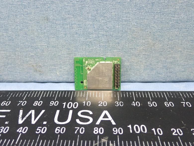
B3QT99H209
Mar 14, 2021IEEE802.11a/b/g/n/ac (1x1)+ BT 5.0 Combo Module
Equipment Class
DTS - Digital Transmission System
B3Q8V9313
Jul 09, 2015Mobile Printer
Equipment Class
DTS - Digital Transmission System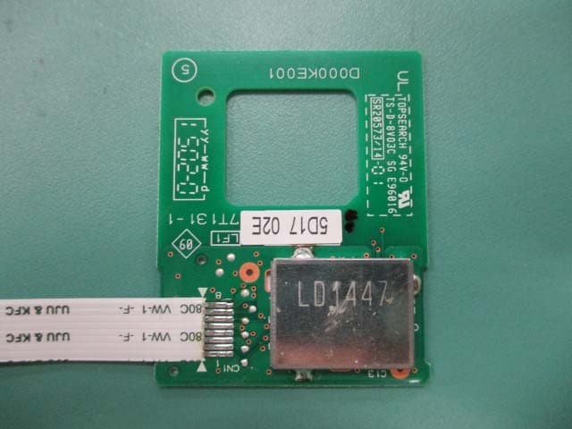
B3QBRNF13M002
Jul 06, 2015NFC Module
Equipment Class
DXX - Part 15 Low Power Communication Device Transmitter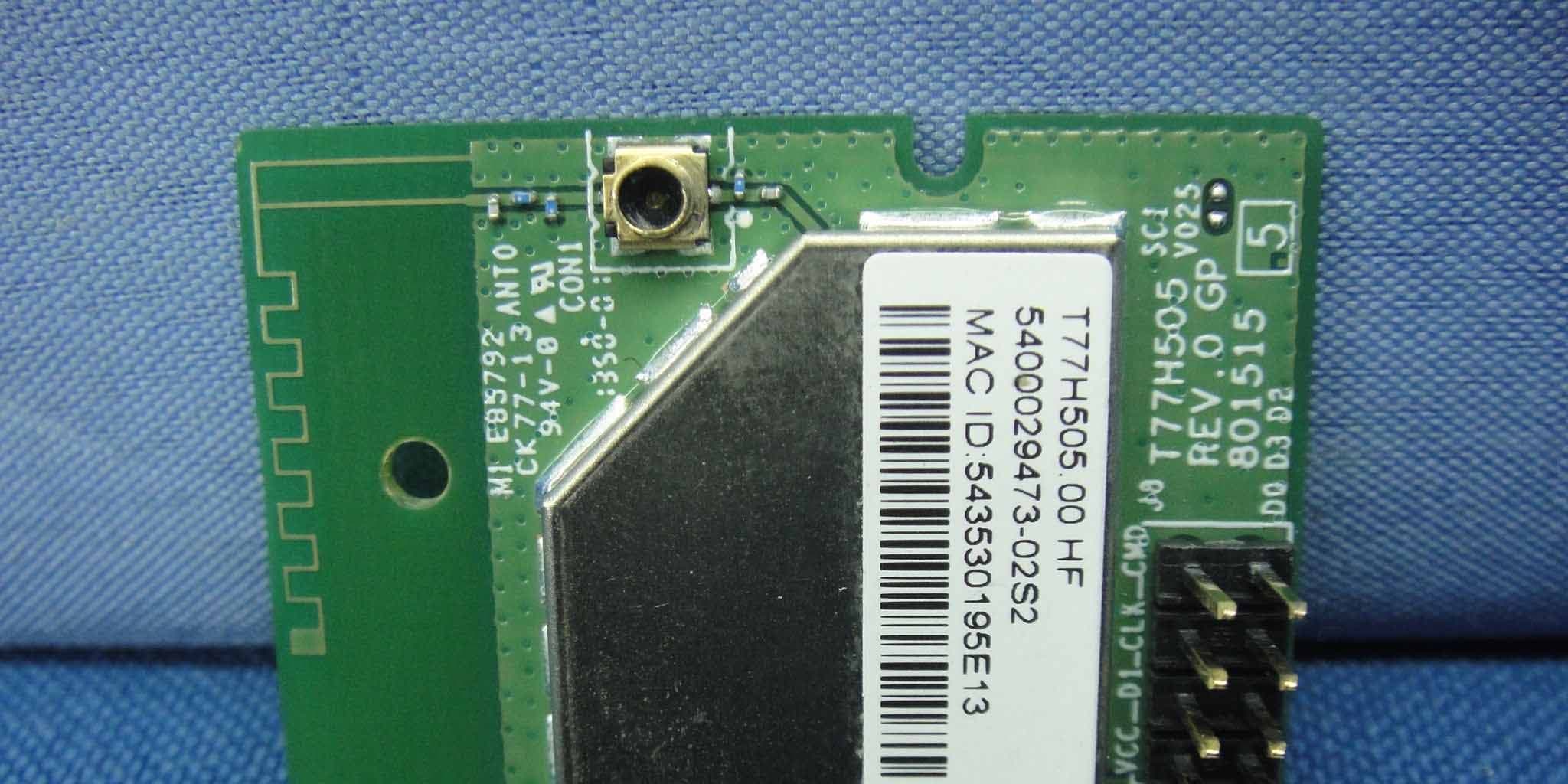
B3QT77H505
May 07, 2014IEEE802.11b/g/n Wi-Fi module
Equipment Class
DTS - Digital Transmission System