B3W-VX150Low Power FM Broadcaster
Nautel Maine Inc
Click to zoom
Application Details
- Equipment Class
- TBC - Licensed Broadcast Station Transmitter
- Date of Grant
- Feb 28, 2021
- Application Purpose
- Original Equipment
- Date of Application
- Feb 28, 2021
- Equipment Note
- Low Power FM Broadcaster
- Frequency Range
- 88.00000000 - 108.00000000
- Company
- Nautel Maine Inc
- Country
- United States
Documents & Files
Document Text
Text extracted from the exhibit documents filed with the FCC. Open a document above to read the original.
Users Manual
1: INSTALLATION MANUAL VX150 TO VX2 FM B ROADCAST TRANSMITTER Document ID: NHB-VX150-VX2-INS Version:0.3 Issue Date:2021-01-14 Status:Preliminary Making Digital Radio Work VERSION 0.3 2021-01-14PAGE III VX150 TO VX2 INSTALLATION MANUAL Contact Information Nautel Limited 10089 Peggy’s Cove Road Hackett’s Cove, NS Canada B3Z 3J4 Toll Free: +1.877.6NAUTEL (662.8835) (Canada & USA only) or Phone: +1.902.823.3900 or Fax: +1.902.823.3183 Nautel Inc. 201 Target Industrial Circle Bangor, Maine USA 04401 Phone: +1.207.947.8200 Fax: +1.207.947.3693 Customer Service (24-hour support) +1.877.628.8353 (Canada & USA only) +1.902.823.5100 (International) Email: [email protected] Web: www.nautel.com The comparisons and other information provided in this document have been prepared in good faith based on publicly available information. For verification of materials, the reader is encouraged to consult the respective manufacturer's most recent publication on the official website or through contact with Customer Service. © Copyright 2020 NAUTEL. All rights reserved. VX150 TO VX2 INSTALLATION MANUALTABLE OF CONTENTS VERSION 0.3 2021-01-14PAGE 1.V CONTENTS Contact Information 1.iii RELEASE CONTROL RECORD1.vii About This Manual1.xi Technical Support 1.xi VX Series Transmitter Manuals 1.xi Nautel Website / Online Resources 1.xii About Safety1.xv Electrical Hazards 1.xv Lightning Hazards 1.xvi RF Hazards 1.xvi Toxic Hazards 1.xvi Other Hazards 1.xvi Safety Precautions1.xvii Personal Safety 1.xvii Site Safety 1.xviii Equipment Safety 1.xx Description1.1.1 Capabilities 1.1.1 Transmitter Configuration 1.1.2 Options 1.1.3 Pre-installation tasks1.2.1 Preparing for Installation 1.2.1 Selecting a Location for the Transmitter 1.2.2 VX150 TO VX2 INSTALLATION MANUALTABLE OF CONTENTS PAGE 1.VIVERSION 0.3 2021-01-14 Physical Requirements1.3.1 Dimensions 1.3.1 Clearances 1.3.2 Weight 1.3.2 Cooling requirements1.4.1 Air Flow in the Transmitter 1.4.1 Cooling 1.4.2 Heating 1.4.2 Electrical Requirements1.5.1 Electrical Power 1.5.1 Station Reference Ground 1.5.3 RF Output Requirements1.6.1 Antenna Feed Cable 1.6.1 Antenna System 1.6.1 Program Inputs1.7.1 Analog Inputs 1.7.1 Digital Inputs 1.7.2 Other Features 1.7.2 Control and Monitor Wiring1.8.1 Front Panel UI Control 1.8.1 Remote Inputs 1.8.2 Remote Outputs 1.8.4 Analog Outputs 1.8.6 Web Based AUI Control 1.8.7 SNMP Control/Monitoring 1.8.8 Email Server 1.8.9 VX150 TO VX2 INSTALLATION MANUALTABLE OF CONTENTS VERSION 0.3 2021-01-14PAGE 1.VII External Interlock 1.8.9 Unboxing and Installing the Transmitter1.9.1 Unboxing the Transmitter 1.9.1 Mounting the Transmitter 1.9.2 Completing External Connections1.10.1 Connecting Ac Power 1.10.2 Connecting Station Reference Ground 1.10.3 Installing and Connecting the RF Feed Cable 1.10.4 Connecting Program Inputs 1.10.6 Connecting Remote Control/Monitor Wiring 1.10.7 Commissioning1.11.1 Pre-Commissioning Tasks 1.11.2 Commissioning 1.11.3 Going On-Air 1.11.4 Network Setup 1.11.5 Parts and Tools1.12.1 Contacting Nautel 1.12.1 Parts Supplied by Nautel 1.12.2 Parts Not Supplied by Nautel 1.12.2 Parts Ordering 1.12.2 Module Exchange Program 1.12.3 Tools for Installation 1.12.3 VX150 TO VX2 INSTALLATION MANUALTABLE OF CONTENTS PAGE 1.VIIIVERSION 0.3 2021-01-14 Pre-Installation / Installation Assistance1.13.1 Pre-Installation Consulting 1.13.1 Installation and Commissioning Service 1.13.1 Online Documentation 1.13.2 On-Site Support 1.13.3 Training 1.13.3 Standard Warranty 1.13.4 Extended Warranties 1.13.7 List of terms1.14.1 VX150 TO VX2 INSTALLATION MANUAL VERSION 0.3 2021-01-14PAGE VII RELEASE CONTROL RECORD ISSUEDATEREASON 0.12020-09-01Preliminary release for VX150 to VX2 models. Supports hardware versions: VX150, VX300, VX600 (NARF81) VX1 (NARF79) VX1.5. VX2 (NARF80) Supports software version VX SW 1.0 and later. 0.22020-12-01Implemented Engineering review comments, various sections 0.32021-01-14Added Table 1.1.1 for Transmitter Configuration VX150 TO VX2 INSTALLATION MANUAL PAGE VIIIVERSION 0.3 2021-01-14 VX150 TO VX2 INSTALLATION MANUAL VERSION 0.3 2021-01-14PAGE XI About This Manual Technical Support Nautel offers technical support to customers over the Internet and by telephone. Nautel’s customer support team will answer your questions and work with you to identify and resolve problems. For 24-hour technical support, call toll free at 1.877.628.8353 (in USA and Canada only) or call 1.902.823.5100 (international) or find us on the Internet at http://www.nautel.com. For parts and tools information, see “Parts and Tools” on page 2.10.1 of the VX Pre-Installation/ Installation manual. For extended warranty information, see “Pre-installation assistance” on page 1.10.1 of the VX Pre-Installation/Installation manual. VX Series Transmitter Manuals The VX series documentation suite includes the following documents: Nautel Site Protection Manual Provides detailed information about protecting your site from lightning-related hazards. Volume 1, VX Installation (INS) Manual Provides instructions and reference information needed when planning and preparing for the installation of the VX series transmitter. Volume 2, VX Operating and Maintenance (OPS) Manual Provides instructions for operating and maintaining the VX series transmitter. Volume 3, VX Troubleshooting (TRB) Manual Provides instructions for troubleshooting the VX series transmitter and replacing its sub-assemblies. It also contains detailed technical information, including parts lists, electrical schematics and mechanical drawings. VX150 TO VX2 INSTALLATION MANUAL PAGE XIIVERSION 0.3 2021-01-14 Nautel Website / Online Resources The Nautel website provides useful resources to keep you up to date on your VX series transmitter. Frequently asked questions (FAQ), How To Videos, latest software versions are just a few of the many resources available. Nautel User Group (NUG) The Nautel Support website allows access to product manuals and the RF Toolkit when you create a free NUG account (see Figu…
Text truncated - open the document above for the full version.
Users Manual
2: OPERATIONS & MAINTENANCE MANUAL VX150 TO VX2 TRANSMITTER Document ID: NHB-VX150-VX2-OPS Version:0.2 Issue Date:2021-01-14 Status:Preliminary Making Digital Radio Work VERSION 0.2 2021-01-14PAGE III VX-LP OPERATIONS & MAINTENANCE MANUAL Contact Information Nautel Limited 10089 Peggy’s Cove Road Hackett’s Cove, NS Canada B3Z 3J4 Toll Free: +1.877.6NAUTEL (662.8835) (Canada & USA only) or Phone: +1.902.823.3900 or Fax: +1.902.823.3183 Nautel Inc. 201 Target Industrial Circle Bangor, Maine USA 04401 Phone: +1.207.947.8200 Fax: +1.207.947.3693 Customer Service (24-hour support) +1.877.628.8353 (Canada & USA only) +1.902.823.5100 (International) Email: [email protected] Web: www.nautel.com The comparisons and other information provided in this document have been prepared in good faith based on publicly available information. For verification of materials, the reader is encouraged to consult the respective manufacturer's most recent publication on the official website or through contact with Customer Service. © Copyright 2020 NAUTEL. All rights reserved. VX150 TO VX2 OPERATIONS & MAINTENANCE MANUALTABLE OF CONTENTS VERSION 0.2 2021-01-14PAGE 2.V CONTENTS Contact Information 4.1.iii RELEASE CONTROL RECORDvii Description2.1.1 Ac-Dc Power Stage 2.1.1 Control/Excitation Stage 2.1.4 RF Stage 2.1.5 Operating the Transmitter2.2.1 User Interface Options 2.2.3 Front Panel User Interface (FPUI) 2.2.4 Advanced User Interface (AUI) 2.2.7 Managing and Displaying Widgets 2.2.13 AUI Menu Page 2.2.25 Viewing Transmitter Alarms 2.2.28 Viewing Transmitter Status - using the AUI 2.2.30 Meters 2.2.31 Presets 2.2.32 Preset Scheduler 2.2.50 Audio Player 2.2.53 System Settings 2.2.57 Configuring Remote Inputs and Outputs 2.2.101 Routine Maintenance2.3.1 Scheduled Maintenance 2.3.1 Replacing an Air Filter 2.3.1 Performing On-Air Checks 2.3.3 VX150 TO VX2 OPERATIONS & MAINTENANCE MANUALTABLE OF CONTENTS PAGE 2.VIVERSION 0.2 2021-01-14 Non-standard maintenance2.4.1 Upgrading Software 2.4.1 OS Password Recovery 2.4.4 SD Card Replacement 2.4.4 List of terms2.5.1 VX150 TO VX2 OPERATIONS & MAINTENANCE MANUAL VERSION 0.2 2021-01-14PAGE VII RELEASE CONTROL RECORD ISSUEDATEREASON 0.12020-12-01Initial release for VX low power models. Supports hardware versions: VX150, VX300, VX600 (NARF81) VX1 (NARF79) VX1.5. VX2 (NARF80) Supports software version VX SW 1.0 and later. 0.22021-01-14Implemented Engineering review changes in sections VX-LP OPERATIONS & MAINTENANCE MANUAL PAGE VIIIVERSION 0.2 2021-01-14 VX150 TO VX2 OPERATIONS & MAINTENANCE MANUALDESCRIPTION VERSION 0.2 2021-01-14PAGE 2.1.1 SECTION 2.1: DESCRIPTION This section provides a high-level description of the transmitter’s key sections. The transmitter circuitry is subdivided into four basic stages: Ac-Dc Power Stage Control/Excitation Stage - see page 2.1.4 RF Stage - see page 2.1.5 R efer to the functional block diagram, Figure 3.1.1 on page 3.1.9. VX150 to VX2 Electrical Schematics Some descriptions in this section refer to electrical schematics (SD-#s). These are located in Section 4 of the VX150 to VX2 Troubleshooting Manual. Ac-Dc Power Stage See electrical schematic Figure SD-1. The ac-dc power stage provides power to operate the low voltage power supply, which generates the +12 dc voltage that is used throughout the transmitter. This supplies the voltage to operate cooling fans, IPA and power the PWBs. The ac-dc power stage also contains a dc power supply that provides positive dc voltage (PA volts) f or the transmitter's RF power amplifier. The output voltage range of the dc power supply varies with the model. F or VX150 to VX600 transmitters, the output voltage range is between +18 and 53 V dc. For VX1to VX2 t ransmitt ers, the output voltage range is between +23 and 65 V dc. For normal operation, VX150 to VX600 transmitters accept a single-phase, 90 - 265 V ac (220 V ac nominal) ac input voltage. For normal operation, VX1 to VX2 transmitters accept a single-phase, 185 - 265 V ac (220 V ac nominal) ac input voltage. NOTE : VX1 to VX2 transmitters can operate from a 90-185 V ac input, but will have reduced output power. The ac-dc power stage consists of Power Supply Interface PWB (A4), low voltage power supply (LVPS) ( U2) and power supply (U3). VX150 TO VX2 OPERATIONS & MAINTENANCE MANUALDESCRIPTION PAGE 2.1.2VERSION 0.2 2021-01-14 Power Supply Interface PWB See electrical schematic Figure SD-1. The Power Supply (PS) Interface PWB (A4): interfaces between the ac input and the LVPS and the power supply. distributes LVPS voltage to the RF drive (exciter) stage and the control/monitor stage. distributes PA voltage to the RF power stage and the control/monitor stage. controls, with the controller module, the LVPS output voltage. provides RS485 serial communication between the system interface PWB and the power supply. provides status and alarm outputs from the LVPS and power supply, consisting of Module Present, Power Fail Warning, Rectifier Fault and Overtemp Warning (provided to the Module Control/Interface PWB over a serial bus). Low Voltage Power Supply See electrical schematic Figure SD-1. LVPS module (U2) converts the ac input voltage to the regulated output (+12 V dc). This voltage is used to power all the PWBs, the cooling fans and the IPA. Power Supply Modules See electrical schematic Figure SD-1. Power supply module U3 converts the ac input voltage to a regulated dc supply (PA volts) for the RF amplifier and provides an output voltage between 18 V and 53 V for the VX150 to VX600, and between 23 and 65 V dc for VX1 to VX2). The modules regulate the output voltage based on a serial control input from the Power Supply Interface PWB (A4). The supply also senses out-of-regulation on the ac input and dc output, and applies a Power Fail Warning signal to the Exciter PWB. Both conditions cause the power supply to shut itself down, thus shutting down the transmitter's RF output. All power supply module signals are applied to the exciter for system level…
Text truncated - open the document above for the full version.
Users Manual
3: TROUBLESHOOTING MANUAL VX150 TO VX2 FM BROADCASTTRANSMITTER Document ID: NHB-VX150-VX2-TRB Version:0.1 Issue Date:2020-12-01 Status:Preliminary VERSION 0.1 2020-12-01PAGE III VX150 TO VX2 TROUBLESHOOTING MANUAL Contact Information Nautel Limited 10089 Peggy’s Cove Road Hackett’s Cove, NS Canada B3Z 3J4 Toll Free: +1.877.6NAUTEL (662.8835) (Canada & USA only) or Phone: +1.902.823.3900 or Fax: +1.902.823.3183 Nautel Inc. 201 Target Industrial Circle Bangor, Maine USA 04401 Phone: +1.207.947.8200 Fax: +1.207.947.3693 Customer Service (24-hour support) +1.877.628.8353 (Canada & USA only) +1.902.823.5100 (International) Email: [email protected] Web: www.nautel.com The comparisons and other information provided in this document have been prepared in good faith based on publicly available information. For verification of materials, the reader is encouraged to consult the respective manufacturer's most recent publication on the official website or through contact with Customer Service. © Copyright 2020 NAUTEL. All rights reserved. VX150 TO VX2 TROUBLESHOOTING MANUALTABLE OF CONTENTS VERSION 0.1 2020-12-01PAGE 3.V CONTENTS Contact Information 3.iii Responding to alarms3.1.1 Corrective Maintenance 3.1.1 Electrostatic Protection 3.1.3 Identifying and Troubleshooting an Alarm 3.1.4 Replacement Procedures 3.1.17 Pre-Amplifier/IPA PWB Replacement 3.1.18 Power Amplifier PWB Replacement 3.1.20 Power Supply Module Replacement 3.1.23 Parts Information3.2.1 Family Tree 3.2.1 How to Locate Information About a Specific Part 3.2.1 Column Content 3.2.2 Reading Electrical Schematics3.3.1 Component Values 3.3.1 Graphic and Logic Symbols 3.3.1 Reference Designations 3.3.1 Unique Symbols 3.3.2 Identifying Schematic Diagrams 3.3.2 Structure of Schematics 3.3.3 Locating Schematic Diagram(s) for a Functional Block 3.3.3 Locating a Part or Assembly on a Schematic 3.3.4 VX150 TO VX2 TROUBLESHOOTING MANUALTABLE OF CONTENTS PAGE 3.VIVERSION 0.1 2020-12-01 Mechanical Drawings3.4.1 Identifying Mechanical Drawings 3.4.1 Content of Mechanical Drawings 3.4.1 Locating a Part or Assembly on a Mechanical Drawing 3.4.1 List of terms3.5.1 VX150 TO VX2 TROUBLESHOOTING MANUAL VERSION 0.1 2020-12-01PAGE VII RELEASE CONTROL RECORD ISSUEDATEREASON 0.12020-12-01Preliminary release for VX150 to VX2. Supports hardware versions: VX150, VX300, VX600 (NARF81) VX1 (NARF79) VX1.5. VX2 (NARF80) Supports software version VX SW 1.0 and later. VX150 TO VX2 TROUBLESHOOTING MANUAL PAGE 3.VIIIVERSION 0.1 2020-12-01 VX150 TO VX2 TROUBLESHOOTING MANUALRESPONDING TO ALARMS VERSION 0.1 2020-12-01PAGE 3.1.1 SECTION 3.1: RESPONDING TO ALARMS This section provides instructions you need when performing troubleshooting on the VX150 to VX2 transmitter. This section includes the following topics: Corrective Maintenance Electrostatic Protection - see page 3.1.3 Identifying and Troubleshooting an Alarm - see page 3.1.4 Replacement Procedures - see page 3.1.17 If none of the procedures and alarms described in this section address your problem, contact Nautel for assistance. See “Technical Support” in the Installation Manual. Corrective Maintenance Corrective maintenance procedures consist of identifying and correcting defects or deficiencies that arise during transmitter operation. Local and/or remote alarm signals are generated when a malfunction occurs. If an alarm condition is caused by a malfunction in the RF power stage, the transmitter may maintain operation at a reduced RF output level. The nature of the fault – and station policy – will dictate whether an immediate maintenance response is necessary. Fault analysis and rectification may be conducted from three different levels, with a different technical competence level required for each: on-air troubleshooting, remote or local, and off-air troubleshooting. On-Air Troubleshooting On-air troubleshooting can be performed from a remote location, or locally at the transmitter site. Remote Troubleshooting Remote on-air troubleshooting consists of monitoring the transmitter's radiated signal using an on-air monitor or via a LAN connection, and observing the status of each remote fault alarm indicator. Information obtained from these sources should enable an operator to decide whether an alarm response may be deferred to a more convenient time, an immediate corrective action must be taken, or CAUTION! The transmitter contains many solid state devices that may be damaged if subjected to excessive heat or high voltage transients. Take every effort to ensure that circuits are not overdriven or disconnected from their loads while turned on. VX150 TO VX2 TROUBLESHOOTING MANUALRESPONDING TO ALARMS PAGE 3.1.2VERSION 0.1 2020-12-01 if a standby transmitter must be enabled (if one is available). It is recommended that the significance of remote indications, and the appropriate responses, be incorporated into a station's standard operating procedures. Refer to “Identifying and Troubleshooting an Alarm” on page 3.1.4 to determine the remedial action required for a given fault. Local Troubleshooting Local on-air troubleshooting consists of monitoring the transmitter's integral meters and fault alarm indicators. Analysis of this data will normally identify the type of fault, and in most cases will determine what corrective action must be taken. Refer to “Identifying and Troubleshooting an Alarm” on page 3.1.4 to determine the remedial action required for a given fault. Off-Air Troubleshooting Off-air troubleshooting must be performed when routine on-air calibration adjustments will not restore operation. It is recommended that the transmitter’s output be connected to a precision 50 resistive dummy load (rated for at least the maximum transmitter power rating) before starting off-air troubleshooting procedures. If an appropriate dummy load is not available, troubleshooting for a majority of faults can be performed with RF power turned off. The transmitter may remain connected to its antenna system for these procedure…
Text truncated - open the document above for the full version.
ID Label/Location Info
0.25 0.50 0.125 3.250 3.500 0.125 2 PLACES SCR-1931 NOTE: PHOTOSENSITIVE ANODIZED ALUMINUM PROCESSED FOR WHITE METAL CHARACTERS ON BLACK BACKGROUND REV.DCN#REVISION DESCRIPTIONDWN BYAPPD BYAPPD DATE AINITIAL ISSUEJPDM.WOODS02DEC2020 3RD ANGLE PROJECTION DO NOT SCALE DRAWING UNLESS SPECIFIED TOLERANCE ON TORQUE VALUES SHALL BE +/-10% ALL MATERIALS SHALL MEET THE ASTM SPEC REFERENCED IN THE 'MATERIAL' SECTION OF THE TITLE BLOCK. THE INFORMATION CONTAINED IN THIS DRAWING IS THE SOLE PROPERTY OF NAUTEL. ANY REPRODUCTION IN PART OR AS A WHOLE WITHOUT WRITTEN PERMISSION FROM NAUTEL IS PROHIBITED. PROPRIETARY & CONFIDENTIAL ALL ELECTRONIC ASSEMBLIES ARE TO MEET LATEST REVISION OF IPC-A-610 OR IPC-A-620(CLASS 2 ) UNLESS OTHERWISE SPECIFIED. WHEN OTHERWISE SPECIFIED REFER TO THE NAUTEL STANDARD AS APPLICABLE. SHEET 1 OF 1 37338 DRAWING NO CODE IDENT NO SIZE A TITLE MATERIAL UNLESS OTHERWISE STATED: DIMENSIONS ARE IN INCHES/WEIGHT IN POUNDS INSIDE BEND RAD = MATL THK FOR TOLERANCE INTERPRETATION SEE Q0001.WS or (FINISHES & FABRICATION ) 3 PLACE DECIMAL .010 < 24 3 PLACE DECIMAL .020 > 24 2 PLACE DECIMAL .020 1 PLACE DECIMAL .030 FRACTIONAL 1/32 SURFACE FINISH: SEE NOTE LABEL, ANODIZED ALUM, XMTR, LPFM, VX150 235-5070 .032 THK ALUM ALLOY 5052-H34
ID Label/Location Info
FCC LPFM LABEL LOCATION 173.766.84 0.22 5.58
Test Report
Certificates and reports shall not be reproduced except in full, without the written permission of H.B Compliance Solutions, LLC. Intentional Radiator Test Report For the Nautel Limited FM Broadcast Transmitter Model VX150 Tested under The FCC Rules contained in Title 47 of the CFR, Part 73 Subpart G and Part 74 Subpart L for Radio Broadcast Services February 26, 2021 Prepared for: Nautel Limited 10089 Peggy’s Cove Road, Hackett’s Cove, Nova Scotia, Canada B3Z 3J4 Prepared By: H.B. Compliance Solutions 5005 S. Ash Avenue, Suite A-10 Tempe, Arizona 85282 Reviewed By: Hoosamuddin Bandukwala Cert # ATL-0062-E Engineering Statement: The measurements shown in this report were made in accordance with the procedure indicated, and the emissions from this equipment were found to be within the limits applicable. I assume full responsibility for the accuracy and completeness of these measurements, and for the qualifications of all persons taking them. It is further stated that upon the basis of the measurement made, the equipment tested is capable of operation in accordance with the requirements of Part 74 of the FCC Rules under normal use and maintenance. All results contained herein relate only to the sample tested. HBCS Report # EMC_20038 Rev1 Page 2 of 33 Report Status Sheet Revision # Report Date Reason for Revision Ø August 21, 2020 Initial Issue 1 February 26, 2021 Corrected high band channel HBCS Report # EMC_20038 Rev1 Page 3 of 33 Table of Contents EXECUTIVE SUMMARY ............................................................................................ 4 1. Testing Summary ........................................................................................ 4 EQUIPMENT CONFIGURATION ................................................................................ 5 1. Overview .................................................................................................... 5 2. Test Facility ................................................................................................. 6 3. Description of Test Sample ......................................................................... 7 4. Equipment Configuration ........................................................................... 7 5. Support Equipment .................................................................................... 7 6. Ports and Cabling Information .................................................................... 7 7. Method of Monitoring EUT Operation ........................................................ 8 8. Mode of Operation ..................................................................................... 8 9. Modifications ............................................................................................. 8 10. Disposition of EUT ...................................................................................... 8 Criteria for Intentional Radiators ............................................................................ 9 1. RF Power Output ........................................................................................ 9 2. Modulation Characteristics ....................................................................... 12 3. Occupied Bandwidth (Emission Mask) ...................................................... 15 4. Spurious Emissions at Antenna Terminals ................................................ 19 5. Radiated Spurious Emissions .................................................................... 23 6. Frequency Stability vs Temperature ......................................................... 27 7. Frequency Stability vs Voltage .................................................................. 29 8. Necessary Bandwidth ............................................................................... 31 9. Test Equipment ........................................................................................ 32 10. Measurement Uncertainty ....................................................................... 33 HBCS Report # EMC_20038 Rev1 Page 4 of 33 EXECUTIVE SUMMARY 1. Testing Summary These tests were conducted on a sample of the equipment for the purpose of demonstrating compliance with CFR 47 FCC Part 73 and 74. All tests were conducted using measurement procedure from ANSI C63.4-2014, American National Standard for Methods of Measurement of Radio-Noise Emissions from Low-Voltage Electrical and Electronic Equipment in the range of 9kHz to 40GHz and ANSI C63.26-2015 Procedures for Compliance Testing of Transmitters Used in Licensed Radio Services as appropriate. Test Name Test Method/Standard Result Comments RF Output Power §2.1046; §73.811, §74.1235 Pass Modulation Characteristics §2.1047(a); §73.1590 Pass Occupied Bandwidth §2.1049; §73.317, §74.1236 Pass Spurious Emissions at Antenna Terminals §2.1051; §73.317; §74.1236 Pass Radiated Spurious Emissions §2.1053 Pass Frequency Stability over Temperature Variations §2.1055(a)(1); §73.1545(b); §74.1261 Pass Frequency Stability over Voltage Variations §2.1055(d); §73.1545(b); §74.1261 Pass HBCS Report # EMC_20038 Rev1 Page 5 of 33 EQUIPMENT CONFIGURATION 1. Overview H.B Compliance Solutions was contracted by Nautel Limited to perform testing on the FM Broadcast Transmitter VX150 under the purchase order number 10096213. This document describes the test setups, test methods, required test equipment, and the test limit criteria used to perform compliance testing of the Nautel Limited, FM Broadcast Transmitter VX150. The tests were based on FCC Part 90 Rules. The tests described in this document were formal tests as described with the objective of the testing was to evaluate compliance of the Equipment Under Test (EUT) to the requirements of the aforementioned specifications. Nautel Limited should retain a copy of this document and it should be kept on file for at least five years after the manufacturing of the EUT has been permanently discontinued. The results obtained relate only to the i…
Text truncated - open the document above for the full version.
Test Setup Photos
1 | P a g e Test Setup Photos Nautel – Project 20038 Test Setup Photo # 1 Test Setup Photo # 2 2 | P a g e Test Setup Photo # 3 Test Setup Photo # 4
Contact Information
Applicant
Kevin Rodgers(President)
Test Firm
H.B. Compliance SolutionsHoosamuddin Bandukwala
[email protected]480-684-2969
Technical Specifications
| # | Rule Parts | Frequency Range | Power Output | Emission | Tolerance |
|---|---|---|---|---|---|
| 1 | 73,74 | 88 MHz - 108 MHz | 150 W | 180KF3E | 30.0000000000 Hz |
Other Applications from Nautel Maine Inc

B3W-VX300
Feb 28, 2021Low Power FM Broadcaster
Equipment Class
TBC - Licensed Broadcast Station Transmitter
B3W-VS300HD
Feb 28, 2021Low Power FM HD Radio Transmitter
Equipment Class
TBC - Licensed Broadcast Station Transmitter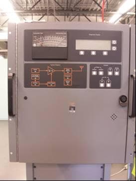
B3WVECTOR125
Mar 11, 2015Nautel VR125
Equipment Class
TNB - Licensed Non-Broadcast Station Transmitter
B3W-VS300
Mar 23, 2011Low Power FM Broadcaster
Equipment Class
TBC - Licensed Broadcast Station TransmitterB3WFM3-5
Feb 08, 1998TBC - Licensed Broadcast Station Transmitter
Equipment Class
TBC - Licensed Broadcast Station Transmitter