B3WVECTOR125Nautel VR125
Nautel Maine Inc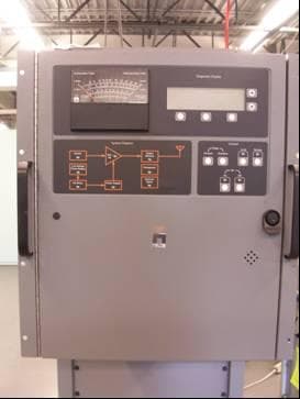
Click to zoom
Application Details
- Equipment Class
- TNB - Licensed Non-Broadcast Station Transmitter
- Date of Grant
- Mar 11, 2015
- Application Purpose
- Original Equipment
- Date of Application
- Mar 11, 2015
- Equipment Note
- Nautel VR125
- Frequency Range
- 0.19000000 - 0.53500000
- Company
- Nautel Maine Inc
- Country
- United States
Documents & Files
Document Text
Text extracted from the exhibit documents filed with the FCC. Open a document above to read the original.
Users Manual
Vector-LP Radio Beacon Transmitter Technical Instruction Manual VR125 VR250 Issue 1.8.1 .................01 February 2015 Nautel Limited 10089 Peggy's Cove Road, Hackett's Cove, NS, Canada B3Z 3J4 T.877 6 nautel (628835) or +1.902.823.2233 F.+1.902.823.3183 [email protected] U.S. customers please contact: Nautel Inc. 201 Target Industrial Circle, Bangor ME 04401 T.877 6 nautel (628835) or +1.207.947.8200 F.+1.207.947.3693 [email protected] e-mail: [email protected] www.nautel.com Copyright 2015 NAUTEL. All rights reserved. Vector-LP Radio Beacon Transmitter Technical Instruction Manual Feb.01.15 IMPORTANT This manual makes frequent references to a mode of operation called ‘beacon and voice’ (e.g., pages 1-1, 3-11, 3-23, 3-30, 4-4, 4-5, 4-7, 6-1 and 6-15). Please ignore these references, as voice operation is not authorized in FCC/FAA compliant transmitters. Vector-LP Radio Beacon Transmitter Technical Instruction Manual Feb.01.15 Warranty by Nautel Limited/Nautel Inc. (herein after referred to as Nautel) Nautel Limited/Nautel Incorporated, hereinafter referred to as Nautel, guarantees all mechanical and electrical parts of the equipment for a period of 18 months from date of shipment. 1. A "Part Failure" shall be deemed to have occurred when the part has become defective, or does not have the characteristics required for the specified equipment performance: (a) When the equipment is operated within the design parameters, and (b) When the equipment is installed and adjusted according to Nautel's prescribed procedures as stated in the instruction manual. 2. Nautel shall provide replacements for all "Parts" at no cost to the Customer when they become defective during the warranty period, and upon the return of the defective part. 3. In the event that a "Part" fails during the warranty period and causes damage to a sub-assembly that cannot be readily repaired in the field, the entire sub-assembly so damaged may be returned to Nautel for repair. The repairs will be made without charge to the Customer. 4. Where warranty replacements or repair are provided under items 2 or 3, Nautel will pay that part of the shipping costs incurred in returning the part/assembly to the Customer. 5. Warranty replacement parts and repair, which are provided under items 2 or 3, shall be guaranteed for a period of ninety days from date of shipment or until the end of the original warranty period, whichever occurs later. 6. Nautel will not assume responsibility for any charges incurred by other than Nautel employees. 7. Nautel shall have the privilege of investigating whether failures have been caused by factors beyond its control. 8. Nautel shall in no event be liable for any consequential damages arising from the use of this equipment. 9. When requesting a warranty repair/replacement, please provide complete and accurate information. Observe the instructions regarding 'Equipment Being Returned to Nautel' on page two of this warranty and provide the information requested. 10. When ordering spare/replacement parts, please provide complete and accurate information. Refer to the parts list of the Repair manual for ordering information. Provide as much of the information requested for 'Equipment Being Returned to Nautel' on page two of this warranty as is practical. The information identified by an asterisk is the minimum required. Nautel Limited Nautel Inc. 10089 Peggy's Cove Road 201 Target Industrial Circle Hackett's Cove NS Canada B3Z 3J4 Bangor ME USA 04401 T. 877 6 nautel (628835) or 1.902.823.2233 T. 877 6 nautel (628835) or 1.207.947.8200 F. 1.902.823.3183 F. 1.207.947.3693 24hr. Answering Service 1.902.823.3900 Customer Service Notice A ‘Technical Assistance’ and ‘Plug-in Module Exchange’ service is available to Nautel users. Factory Support TECHNICAL ASSISTANCE Nautel's field service department provides telephone technical assistance on a 24 hour, seven days a week basis. Requests by other media (facsimile or e-mail) will be responded to the next working day if received after Nautel's normal working hours. Contact the appropriate field service centre from the following: U.S.A. customers use: Nautel Incorporated T. +1.207.947.8200 (24 hours) or 877 6 nautel (628835) 201 Target Industrial Circle F. +1.207.947.3693 Bangor, Maine 04401 All other customers use: Nautel Limited T. +1.902.823.3900 (24 hours) or 877 6 nautel (628835) 10089 Peggy’s Cove Road, F. +1.902.823.3183 Hackett’s Cove, NS, Canada E-Mail [email protected] B3Z 3J4 Web www.nautel.com MODULE EXCHANGE SERVICE In order to provide Nautel customers with a fast and efficient service in the event of a problem, Nautel operates a factory rebuilt, module exchange service which takes full advantage of the high degree of module redundancy in Nautel equipment. This module exchange service is operated from Nautel’s factory in Bangor, Maine and Hackett’s Cove, Nova Scotia. These two locations allow us to provide a quick turn around service to keep our customers on the air. During the transmitter’s warranty period, up to 18 months from shipment, repair and exchange of modules is at no charge to the customer. When the warranty has expired, a charge of 80% of the list price for all exchanged modules is made. If the faulty module is returned to Nautel within 30 days, a credit is issued reducing this charge by one half to 40% of the list price. U.S.A. customers are required to contact our Bangor, Maine facility. Canadian and overseas customers should contact our Nova Scotia, Canada facility. EQUIPMENT BEING RETURNED TO NAUTEL For all equipment being returned to Nautel and all requests for repairs or replacements: Obtain an RMA number from Nautel (you must have an RMA number to return equipment) Mark the item as 'field return' Mark the item with the RMA number assigned by Nautel Address the item to the appropriate Nautel facility Complete and accurate information regarding the equipment being returned will ensure prompt attention and will expedite the dispatch of repl…
Text truncated - open the document above for the full version.
External Photos
FCC Type Approval – Vector LP Pictures 1 | P a g e Vector LP Pictures 1. Vector LP External Pictures Fig 1.1 Front View of Vector LP Fig 1.2 Left Side View of Vector LP Fig 1.3 Right Side View of Vector LP Fig 1.4 Top View of Vector LP FCC Type Approval – Vector LP Pictures 2 | P a g e Fig 1.5 Rear View of Vector LP
ID Label/Location Info
FCC Type Approval – Vector LP Label Location 1 | P a g e Vector LP Label Location Fig 1.0 Diagram of Label Location on Vector LP Fig 2.0 Picture of Label Location on Vector LP
Internal Photos
FCC Type Approval – Vector LP Pictures 1 | P a g e Vector LP Pictures 2. Vector LP Internal Pictures Fig 2.1 Front Door Panel Fig 2.2 Control PWB Fig 2.3 Exciter Chassis Fig 2.4 Exciter Chassis with PDM Driver Cover Removed. FCC Type Approval – Vector LP Pictures 2 | P a g e Fig 2.5 PDM Drive PWB’s Fig 2.6 RF Synthesizer PWB’s Fig 2.7 Power Module Section Fig 2.8 Power Module Section with Power Modules Removed FCC Type Approval – Vector LP Pictures 3 | P a g e Fig 2.9 Interface PWB Fig 2.10 Power Module Section (Closer View) Fig 2.11 Filter Chassis Fig 2.12 Filter PWB FCC Type Approval – Vector LP Pictures 4 | P a g e Fig 2.13 DC Power Supplies FCC Type Approval – Vector LP Pictures 1 | P a g e Vector LP Pictures 3. Vector LP Power Module Pictures Fig 3.1 Front of Power Module Fig 3.2 Control/Interface PWB Fig 3.3 Rear of Power Module Fig 3.4 Switch Mode Power Supply PWB FCC Type Approval – Vector LP Pictures 2 | P a g e Fig 3.5 Modulator PWB Fig 3.6 Power Amplifier PWB
Operational Description
FCC Type Approval – Vector LP Theory of Operation 1 | P a g e Vector LP Theory of Operation The Vector LP is an amplitude modulated non-direction radio beacon (NDB) transmitter designed to transmit Omni-directional signals, which are identified by specific beacon identification (Morse) codes at pre-selected repetition rates. The NDB transmitter is used as an aviation and marine navigation aid, whereby the pilot of an aircraft equipped with direction-finding equipment can determine their bearing to or from the radio beacons fixed location. The Vector LP operates in the LF/MF band at a fixed carrier frequency between 190 kHz to 535 kHz for standard band and 536 kHz to 1250 kHz or 1600 kHz to 1800 kHz for extended band operation. The carrier frequency is internally generated on the RF Synthesizer PWB using direct digital synthesis (DDS) which is referenced to a 10 MHz crystal oscillator. The temperature compensated crystal oscillator (TCXO), which has a frequency stability of 2ppm, along with the DDS design, provides for a total carrier frequency tolerance of +/- 0.0003% over the full operating environmental range. Three types of modulation are available in the Vector LP; Continuous Carrier (CW), Continuous Tone (MCW) and MCW plus Voice. The modulation depth is user adjustable, via the transmitter’s front panel graphical user interface (GUI), from 10% to 100%. Modulating tone frequencies of 400 Hz and 1020 Hz, also selected via the front panel GUI, are internally generated on the Exciter Monitor/Generator PWB using DDS, which provides for a frequency tolerance of +/- 5%. Emission modes consist of; continuous carrier (NON), beacon keyed identification tone (A2A) and beacon with voice (A2A/A3E). Note however that emission modes using voice (A3E) are not authorized for use in FCC compliant systems. In emission mode A2A, the keyed identification code is continuously repeated until the transmitter is switched off. The total length of the identification code (Frame) is user adjustable from 4.0 seconds to 20.0 seconds. After each frame ends, a new frame occurs and the code repeats. Since the Vector LP can be programmed from one to six alphanumeric characters, the rate of transmission depends on the keyed string itself (ICAO). The rate of transmission is outlined in the table below. Keyed String Bit Rate <= 3 Characters with 0 numerals 64 bits/frame <= 3 Characters with 1+ numerals 80 bits/frame 4 Characters with 0 numerals 80 bits/frame 4 Character with 1+ numerals 96 bits/frame 5 Characters with 0 numerals 96 bits/frame 5 Character with 1+ numerals 120 bits/frame 6 Characters with 0 numerals 112 bits/frame 6 Character with 1+ numerals 144 bits/frame FCC Type Approval – Vector LP Theory of Operation 2 | P a g e The transmitter’s RF output power is manually adjusted via the front panel power increase/decrease buttons and front panel GUI. The power can be adjusted from 10% to 100% of rated power for 125W (NON), 187.5Wpeak (A2A @ 100% modulation). However, the transmitter’s absolute maximum output power is factory set and software limited to 10W above its rated power level. This 10W headroom allows for a small power increase when the system is operating in combination with a Nautel ATU providing constant antenna current. Spurious radiation is limited through the use of a band-pass filter at the transmitter’s output. The ATU, which is required for matching the transmitter’s impedance to the antenna’s, provides further suppression of the spurious signals. The transmitter’s output power is generated in the RF Power Module assembly. A Switch Mode Power Supply PWB (SMPS) converts the AC input supply voltage to a high level DC voltage (B+) which is used by the Modulator and Power Amplifier PWB’s to generate the RF output signal. To help improve efficiency, the SMPS generates one of three B+ voltages (55V, 97V & 167V). The B+ voltage that is generated depends on the operating power level. Thus the DC current draw from the SMPS into the amplifying stage also depends on the operating RF power level. The table below shows a comparison between various B+ voltages, DC currents, modulator duty cycle and RF power levels. B+ Voltage Measured B+ Voltage Duty Cycle DC Current (SMPS) RF Output Power 56 V 57.0 V 43.1 % 0.33 A 15.5 W 97 V 98.1 V 42.3 % 0.55 A 45.5 W 167 V 168.5 V 42.3 % 0.94 A 136.7 W FCC Type Approval – Vector LP Model Variants 1 | P a g e Vector LP Model Variants The Vector LP NDB series transmitter is an amplitude modulated non-direction beacon operating in the 190 kHz to 535 kHz frequency band. The transmitter consists of a number of model variants; however, with the exception of a few optional items, the physical appearance, construction and operation of each model is the same. These optional items include a DC backup option and the duality of specific components. Nautel’s submission for FCC Type Approval pertains to the VR125 model of the Vector LP family. This includes model variants, the VR125S (Single Side System) and the VR125D (Dual Side System) and also includes the DC backup option. The VR125 has a maximum operating power level of 125W (N0N, no modulation) or 187.5W (A2A, 100% modulation). A universal AC input allows the VR125 to operate from 90Vac to 270Vac supply, but it also has the option to operate from a 24Vdc or 48Vdc DC backup supply. The DC supply option consists of a battery boost assembly along with a DC/DC low voltage power supply. If installed, the transmitter will automatically switch to the DC backup option if the AC falls below a set threshold value. The Vectors switch mode power supply (SMPS), which uses the AC supply option, and the battery boost assembly, which uses the DC supply option, produce a high DC voltage at their output. These voltage’s, which are identical between the two supply options, are OR’d together within the power module and then used by the modulator and power amplifier to produce RF power. At all times, the non operating supply option, either the SMPS …
Text truncated - open the document above for the full version.
Operational Description
Vector-LP Radio Beacon Transmitter Theory of Operation VR125 VR250 Issue 1.8 ............................. 22 July 2011 Nautel Limited 10089 Peggy's Cove Road, Hackett's Cove, NS, Canada B3Z 3J4 T.877 6 nautel (628835) or +1.902.823.2233 F.+1.902.823.3183 [email protected] U.S. customers please contact: Nautel Inc. 201 Target Industrial Circle, Bangor ME 04401 T.877 6 nautel (628835) or +1.207.947.8200 F.+1.207.947.3693 [email protected] e-mail: [email protected] www.nautel.com Copyright 2011 NAUTEL. All rights reserved. Vector-LP Radio Beacon Transmitter Technical Instruction Manual Page 6-1 (6-2 Blank) Section 6 Theory of Operation Issue 1.8 Vector-LP Radio Beacon Transmitter TECHNICAL INSTRUCTION MANUAL Section 6 THEORY OF OPERATION 6.1 INTRODUCTION The theory of operation for the Vector-LP Radio Beacon transmitter is presented in this section. Frequent reference is made to electrical schematics (e.g., Figure SD-1). They are located in Section 9 of this manual. Circuits that are shown on electrical schematics, but not described in this section are either beyond the scope of this manual or are not used for NDB applications. 6.2 TRANSMITTER OVERVIEW The transmitter operates at one fixed frequency in the LF/MF band (190 kHz to 535 kHz) or in the MF band (536 kHz to 1200 kHz and 1600 kHz to 1800 kHz). It provides up to 125 W (VR125) or 250 W (VR250) of continuous carrier power. It automatically transmits specific beacon identification signals at pre-selected repetition rates. Special codes may also be transmitted when commanded from an external source. Provision is made for local or remote operation of the transmitter as well as antenna fine-tuning through controls on the transmitter's front panel. If the standby option is purchased, provision is made for automatic changeover from the selected main side of the transmitter to the standby side when the selected main side's critical parameters are not met. The transmitter operates from a single phase, 47 Hz to 63 Hz ac power supply (170 V to 270 V ac for VR250; 90 V to 270 V for VR125), using switch mode power supplies. A 48 V dc input option (and 24 V dc for VR125 only) can also be purchased. Emission is continuous carrier (NON) beacon keyed identification tone (A2A) and beacon with voice (A2A/A3A). Local control/monitoring is done using front panel membrane switches and a graphic liquid crystal display. Critical parameters such as forward power, reflected power and antenna current can also be displayed on an analog meter on the front of the transmitter. Remote control and monitoring can be provided over several optional interfaces. The transmitter also has provision to interface with a Nautel antenna tuning unit (ATU), using an isolated RS485 serial link. This ATU link allows the transmitter to regulate antenna current, and therefore maintain constant field strength, by auto- adjusting its output power in accordance with the ATUs antenna current sample. The transmitter circuitry can be represented using four functional stages (see Figure 6-1): x Ac-Dc Power Stage x Exciter Stage x Control/Monitor Stage x RF Power Stage 6.3 AC-DC POWER STAGE See Figures 6-1 and SD-1. The ac-dc power stage accepts the ac power source or optional dc power source and converts it to the necessary low level dc voltages required throughout the transmitter. The ac input voltage is also applied directly to the RF power stage. The ac-dc power stage’s primary components are the ac-dc universal input power supplies (U2 and U3, if used) and the interface PWB (A11). If the dc input option is purchased, the transmitter also includes the dc-dc universal input power supply (U10) and the battery boost PWB (A16A1). Dimensions = mm (inches) Block Diagram – Vector-LP Radio Beacon Transmitter Issue 1.8 Not to Scale Figure 6-1 Page 6-3 (6-4 Blank) PA OPTION) B SUPPLIES LVPS POWER A +/- VDC CONTROL/MONITOR B+ (B) (DC POWER) B+ (A) (DC POWER) +/- VDC (B) EXCITER AND +/- VDC (B) +/- VDC (A) INT SERIAL LINK, MONITOR MODULATOR SMPS DC/DC LVPS DC POWER DUAL AC/DC +/- VDC (A) STAGES CONTROL/MONITOR RF DRIVE MOD DRIVE CONTROL/MONITOR RF POWER STAGE EXTERNAL CONTROL/MONITOR B2050017 VB RS232/RS422 EXT SERIAL LINK PTSN (FOR OPTIONAL MODEM) EXTERNAL AUDIO INPUT POWER SUPPLY DC POWER (OPTIONAL BATTERY) +/- VDC (A) B+ (A) (DC POWER) AC POWER (SINGLE OR DUAL) RF POWER MODULE AC POWER +/- VDC (B) B+ (B) (DC POWER) AC POWER RF FILTERRF POWER PROBE RF OUTPUT (BATTERY BOOST AC/DC POWER STAGE See Figure 6-2 Vector-LP Radio Beacon Transmitter Technical Instruction Manual Page 6-5 Section 6 Theory of Operation Issue 1.8 The ac input is applied through 10 A circuit breaker U5 and line filter U6. The ac voltage for the RF power stage (RF power modules A12 and A13) passes through thermistor RT1 and choke L1. Thermistor RT1 limits the inrush current to the RF power modules. Choke L1 improves the power factor on the ac lines applied to the RF power modules. The ac input is also applied to ac-dc universal power supplies U2 and U3 (U3 optional, for dual side transmitters), which convert the ac voltage to low level dc voltages. The ac input voltage is also applied to the interface PWB (A11) for sampling by the control/monitor stage. Dc voltage is applied from an external 24 V or 48 V battery connected to A16TB1. The dc voltage is fused by F1 and applied to rectifier U8 and line filter U7 before being distributed to dc-dc universal power supply U10 and battery boost PWB A16A1. The battery boost PWB boosts the dc voltage and applies it to the RF power stage via rectifier U9. 6.3.1 Interface PWB See Figures SD-1 and SD-21. The interface PWB (A11) provides an interface between the ac-dc power stage and the rest of the transmitter. It also contains voltage regulators (U1 and U2) that provide 9 V for the optional modem (via E5 and E6) and 24 V (limited to 1A) for the ATU (via E3 and E4). It also provides a dc sample of the ac input voltage to the control/display PWB as an aid in determining if the ac input source …
Text truncated - open the document above for the full version.
Schematics
Vector-LP Radio Beacon Transmitter Schematics VR125 VR250 Issue 1.8 ............................. 22 July 2011 Nautel Limited 10089 Peggy's Cove Road, Hackett's Cove, NS, Canada B3Z 3J4 T.877 6 nautel (628835) or +1.902.823.2233 F.+1.902.823.3183 [email protected] U.S. customers please contact: Nautel Inc. 201 Target Industrial Circle, Bangor ME 04401 T.877 6 nautel (628835) or +1.207.947.8200 F.+1.207.947.3693 [email protected] e-mail: [email protected] www.nautel.com Copyright 2011 NAUTEL. All rights reserved. Vector-LP Radio Beacon Transmitter Technical Instruction Manual Page 9-1 Section 9 Electrical Schematics Issue 1.8 Vector-LP Radio Beacon Transmitter TECHNICAL INSTRUCTION MANUAL Section 9 ELECTRICAL SCHEMATICS 9.1 INTRODUCTION This section contains electrical schematics/ logic diagrams for the subject equipment. Block diagrams, simplified electrical schematics, and/or logic diagrams may be included. Refer to Table 9-1 for an itemized listing. 9.2 COMPONENT VALUES Unless otherwise specified on the logic/ schematic diagram, the following applies: x Resistor values are shown in ohms. (K = 1000 and M = 1 000 000). x Resistor power ratings are not shown when less than 0.5 W. x Capacitor values are shown in microfarads (PF). x Unidentified diodes are part number 1N4938. 9.3 GRAPHIC SYMBOLS The graphic symbols used on electrical schematics are in accordance with American National Standard ANSI Y32.2-1975 - Graphic Symbols for Electrical and Electronic Diagrams. 9.4 LOGIC SYMBOLS The logic symbols used on electrical schematics and logic diagrams are in accordance with American National Standard ANSI Y32.14-1975 - Graphic Symbols for Logic Diagrams. 9.5 REFERENCE DESIGNATIONS Reference designations were assigned in accordance with American National Standard ANSI Y32.16-1975 - Reference Designations for Electrical and Electronic Parts and Equipment. Each electrical symbol is identified with its basic reference designation. To obtain the full reference designation for a specific part, this basic identifier must be prefixed with the reference designation assigned to all higher assemblies. 9.6 UNIQUE SYMBOLOGY Nautel utilizes unique symbology on electrical schematics to describe two-state (logic) inputs/outputs that differ from those inputs/ outputs having only one distinct state or multiple states (analog). 9.6.1 Type of Inputs/Outputs On electrical schematics, names used to describe two-state (logic) inputs/outputs are prefixed by a '#'. Those inputs/outputs representing a one-state or analog signal will have no prefix. 9.6.2 Logic Level/Convention The '#' prefix identifies an input/output that has two distinct states - 'high' and 'low'. A suffix, '+' or '-', identifies the active (true) state of the input/output. The 'high' (+) is the more positive of the two levels used to represent the logic states. The 'low' (-) is the less positive of the two levels used to represent the logic states. Two types of logic, positive and negative, may be represented on a particular schematic. In positive logic, 'high' represents the active (true) state and 'low' represents the inactive (false) state. In negative logic, 'low' represents the active state and 'high' represents the inactive state. 9.7 TROUBLESHOOTING AIDS Waveforms and/or voltage levels are provided on some electrical schematics to aid in troubleshooting. Where applicable, accompanying text is included to establish conditional operating parameters that apply to the corresponding waveforms or voltages. Page 9-2 Vector-LP Radio Beacon Transmitter Technical Instruction Manual Issue 1.8 Section 9 Electrical Schematics 9.8 IDENTIFICATION OF SCHEMATIC DIAGRAMS A number that is both the figure number and the page number identifies each illustration in this section. The numbers are assigned sequentially and are prefixed by the letters 'SD-'. The electrical schematics/logic diagrams included in this section are listed in Table 9-1. 9.9 STRUCTURE OF SCHEMATICS The electrical schematics are structured in a hierarchical format that is based on function and signal flow. Wherever practical, the signal flow is from left to right. Inputs normally originate on the left-hand side and outputs will extend to the right-hand side. Exceptions are shown by an arrow indicating the direction of signal flow. NOTE The physical location of a part/assembly was not necessarily a factor when a schematic was drawn. The full reference designation assigned to a part/assembly, in conjunction with the family tree in Figure 7-1 and the assembly detail drawings in section 10 will identify its location. Figure SD-1 identifies each major stage and its detailed interconnection. Each stage contains cross-references that identify which block is the signal source for inputs or the destination for outputs. When a sub-function is treated as a block in Figure SD-1, its detailed circuit information is included in its own schematic drawing(s), also included in this section. 9.10 LOCATING THE SCHEMATIC DIAGRAM(S) FOR A FUNCTIONAL BLOCK The text inside a functional block provides the key to locating its schematic diagram(s). When a functional block is assigned a reference designation, refer to Table 9-1 with the Nautel nomenclature number and/or the description to identify the appropriate figure number(s), if applicable. 9.11 LOCATING A PART/ ASSEMBLY IDENTIFIED ON A SCHEMATIC The full reference designation assigned to a part/assembly is the key to physically locating that part/assembly. NOTE Full reference designations contain the assembly hierarchical coding. When the end item is divided into units (cabinets), the first coding is a unit number (1, 2, 3, etc). When the end item is divided into assemblies, the first coding is an assembly number (A1, A2, A3, etc). If a unit or an assembly is divided into sub-assemblies, assembly coding that identifies assembly relationship (1A1, A2A1, A2A1A1, etc) is added. Vector-LP Radio Beacon Transmitter Technical Instruction Manual Page 9-3 Section 9 Electr…
Text truncated - open the document above for the full version.
Test Report
www.nemko.com Nemko Canada Inc., a testing laboratory, is accredited by the Standards Council of Canada. The tests included in this report are within the scope of this accreditation Part 87 AVIATION SERVICES.docx; Date: Nov 2014 SCC Accredited LAB LAB Accrédité CCN TM ONE WORLDOURAPPROVAL Test report 273734-1TRFWL Date of issue: February 25, 2015 Applicant: Nautel Limited Product: Vector-LP Model: Model Variants: VR125 VR125S, VR125D FCC ID: B3WVECTOR125 Specifications: FCC 47 CFR Part 87 Aviation Services Report reference ID: 273734-1TRFWL Page 2 of 22 Test location Company name Nemko Canada Inc. Address 303 River Road City Ottawa Province Ontario Postal code K1V 1H2 Country Canada Telephone +1 613 737 9680 Facsimile +1 613 737 9691 Toll free +1 800 563 6336 Website www.nemko.com Site number FCC test site registration number: 176392, IC: 2040A-4 (3 m semi anechoic chamber) Tested by Kevin Rose, Wireless/EMC Specialist Reviewed by Andrey Adelberg, Senior Wireless/EMC Specialist Date February 25, 2015 Signature Limits of responsibility Note that the results contained in this report relate only to the items tested and were obtained in the period between the date of initial receipt of samples and the date of issue of the report. This test report has been completed in accordance with the requirements of ISO/IEC 17025. All results contain in this report are within Nemko Canada’s ISO/IEC 17025 accreditation. Copyright notification Nemko Canada Inc. authorizes the applicant to reproduce this report provided it is reproduced in its entirety and for use by the company’s employees only. Any use which a third party makes of this report, or any reliance on or decisions to be made based on it, are the responsibility of such third parties. Nemko Canada Inc. accepts no responsibility for damages, if any, suffered by any third party as a result of decisions made or actions based on this report. © Nemko Canada Inc. Report reference ID: 273734-1TRFWL Page 3 of 22 Table of contents Table of contents .......................................................................................................................................................................................................... 3 Section 1. Report summary ................................................................................................................................................................................. 4 1.1 Applicant/Manufacturer........................................................................................................................................................................................... 4 1.2 Test specifications .................................................................................................................................................................................................... 4 1.3 Statement of compliance ......................................................................................................................................................................................... 4 1.4 Exclusions ................................................................................................................................................................................................................. 4 1.5 Test report revision history ...................................................................................................................................................................................... 4 Section 2. Summary of test results ....................................................................................................................................................................... 5 2.1 FCC Part 87 test results ............................................................................................................................................................................................ 5 Section 3. Equipment under test (EUT) details ..................................................................................................................................................... 6 3.1 Sample information .................................................................................................................................................................................................. 6 3.2 EUT information ......................................................................................................................................…
Text truncated - open the document above for the full version.
Contact Information
Applicant
Kevin Rodgers(President)
Technical Contact
Nautel Maine Inc.Aaron Grant
[email protected]902-823-3900
201 Target Industrial Circle · Bangor · United States
Test Firm
Nemko Canada Inc. (Ottawa)Charles Neal
Technical Specifications
| # | Rule Parts | Frequency Range | Power Output | Emission | Tolerance |
|---|---|---|---|---|---|
| 1 | 87 | 0.19 MHz - 0.535 MHz | 125 W | 2K04A2A | 3.0000000000 ppm |
Other Applications from Nautel Maine Inc

B3W-VX300
Feb 28, 2021Low Power FM Broadcaster
Equipment Class
TBC - Licensed Broadcast Station Transmitter
B3W-VS300HD
Feb 28, 2021Low Power FM HD Radio Transmitter
Equipment Class
TBC - Licensed Broadcast Station Transmitter
B3W-VX150
Feb 28, 2021Low Power FM Broadcaster
Equipment Class
TBC - Licensed Broadcast Station Transmitter
B3W-VS300
Mar 23, 2011Low Power FM Broadcaster
Equipment Class
TBC - Licensed Broadcast Station TransmitterB3WFM3-5
Feb 08, 1998TBC - Licensed Broadcast Station Transmitter
Equipment Class
TBC - Licensed Broadcast Station Transmitter