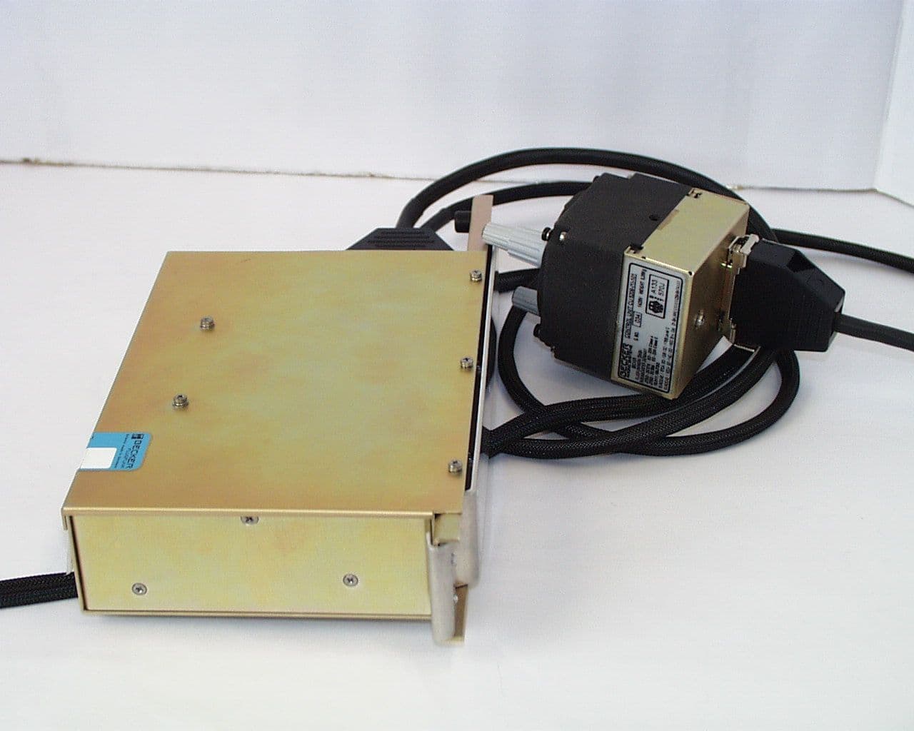
B54ATC3401Aviation Trasponder
Becker Avionics GmbH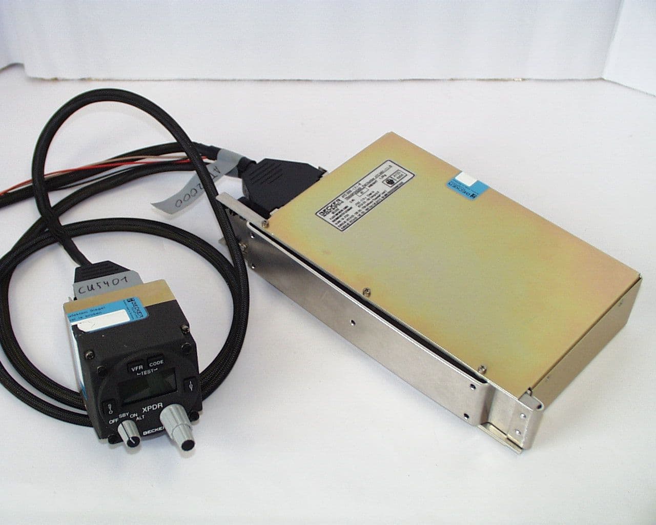
Click to zoom
Application Details
- Equipment Class
- SRT - Radar Transponder
- Date of Grant
- Oct 26, 1999
- Application Purpose
- Original Equipment
- Date of Application
- Jul 19, 1999
- Equipment Note
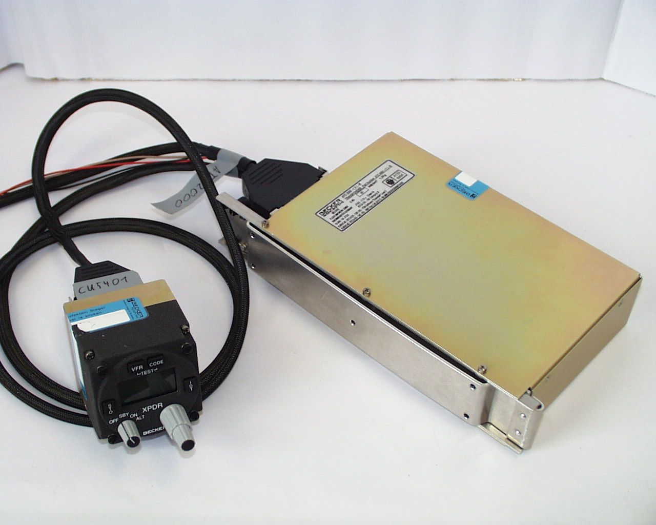
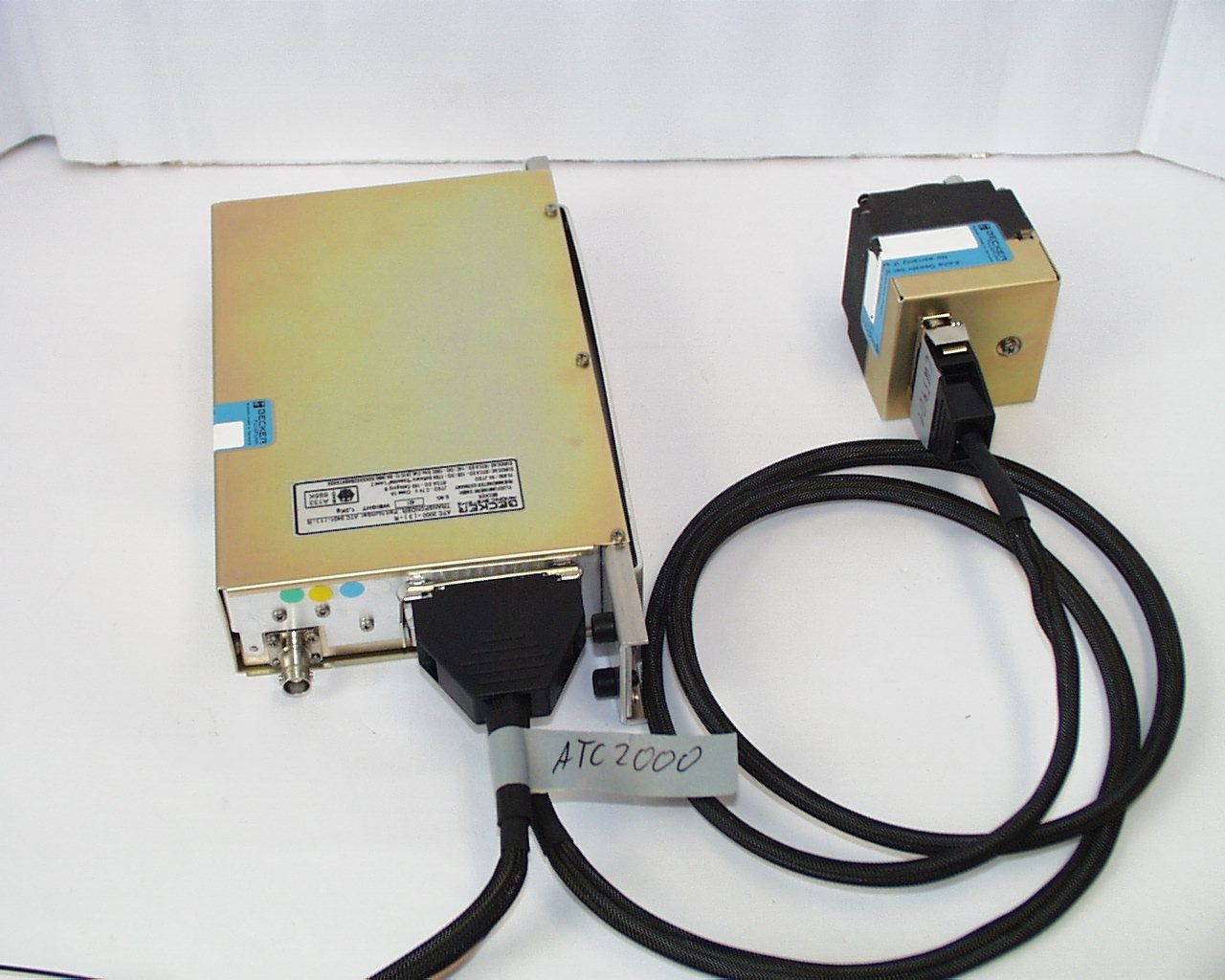
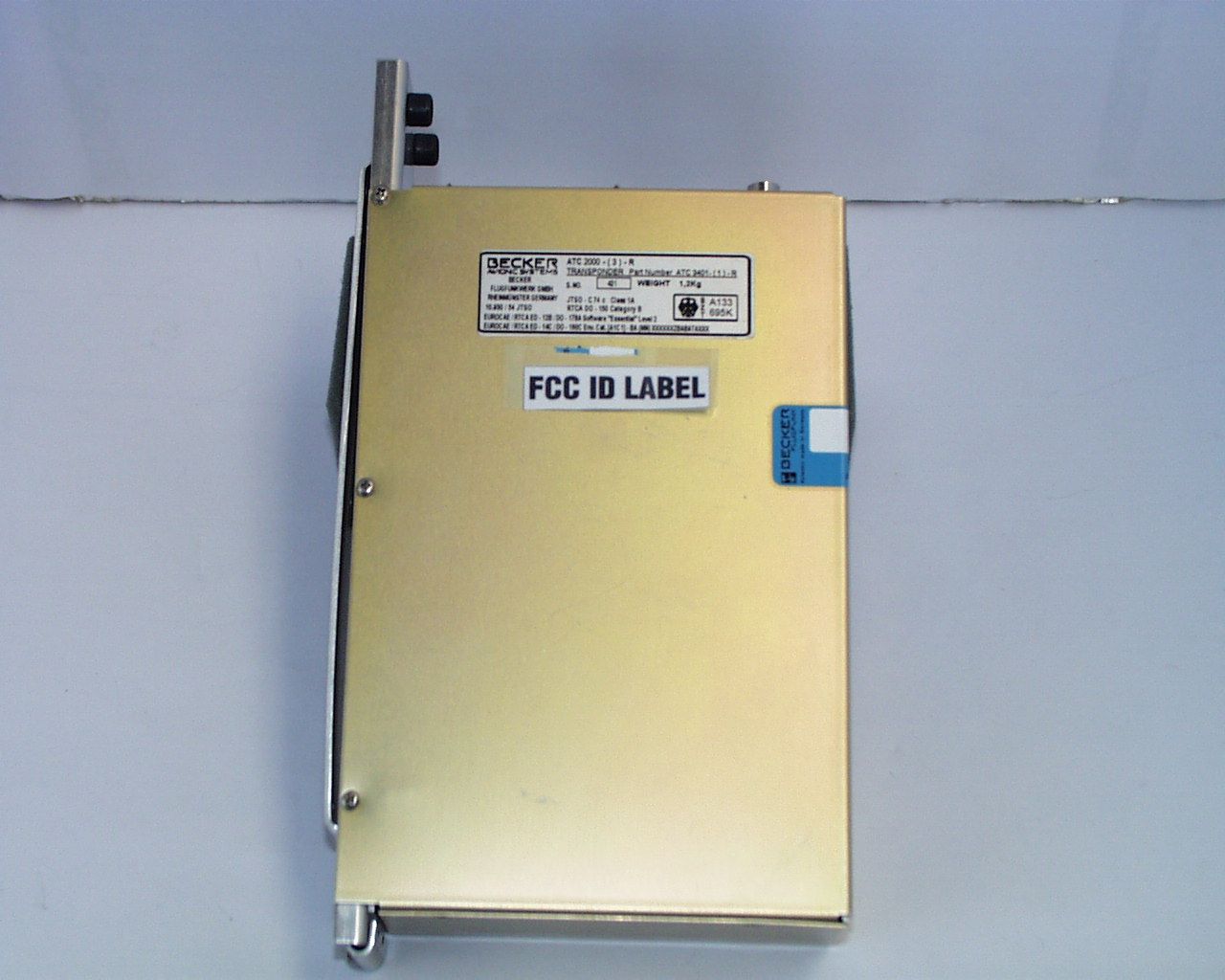
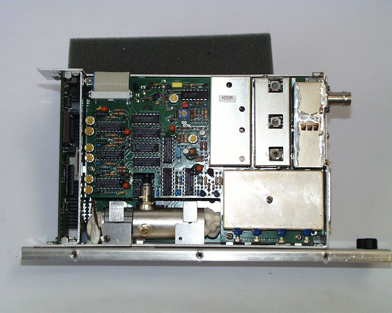
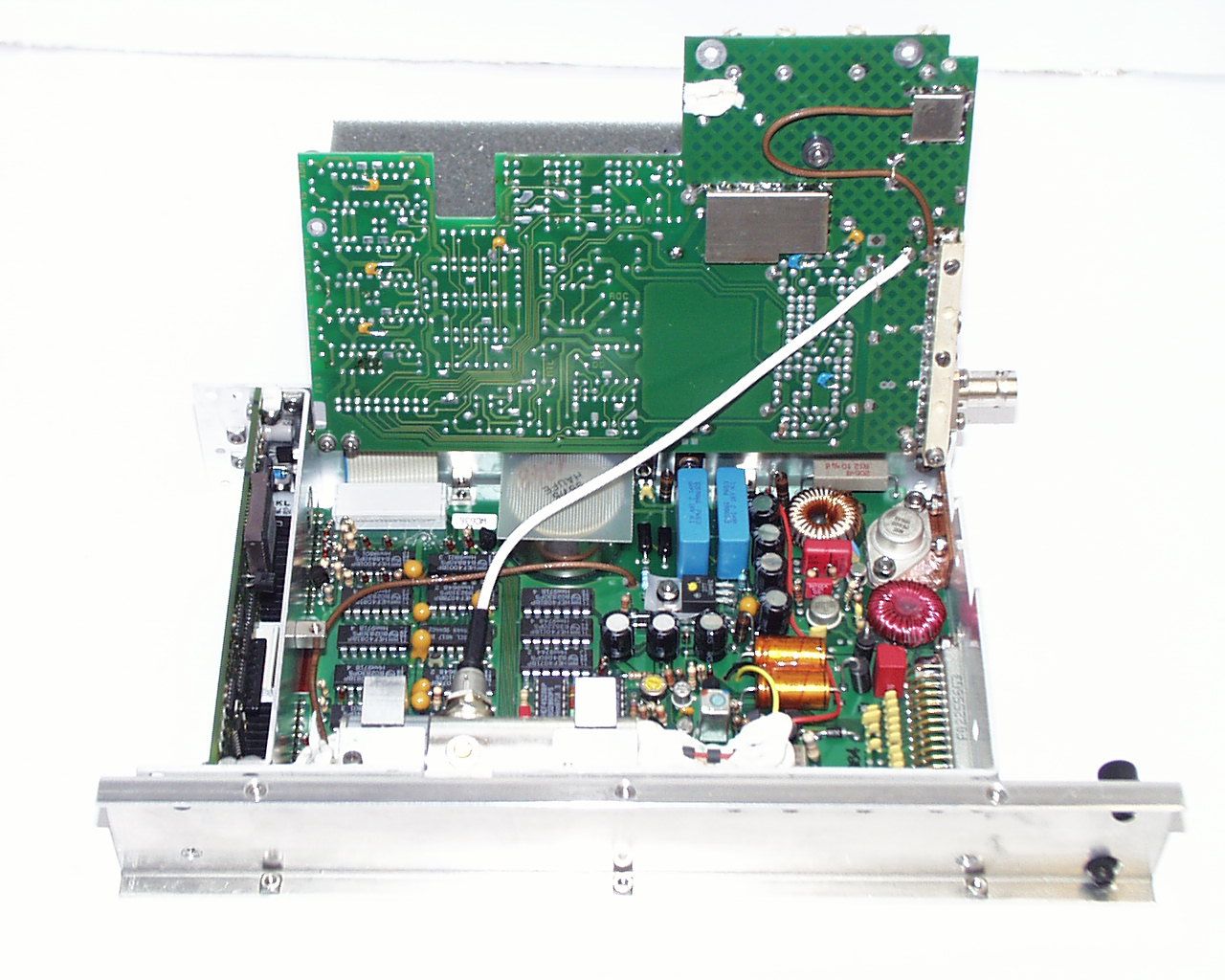
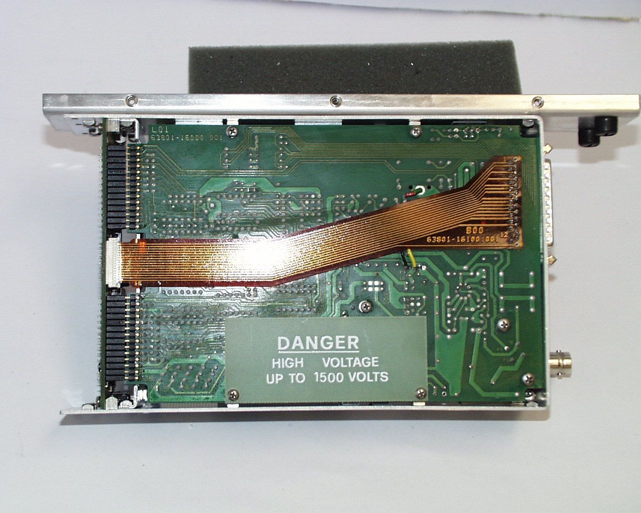
- Aviation Trasponder
- Frequency Range
- 1090.00000000 - 1090.00000000
- Company
- Becker Avionics GmbH
- Country
- Germany
Documents & Files
Document Text
Text extracted from the exhibit documents filed with the FCC. Open a document above to read the original.
Users Manual
Transponder ATC 3401 from Serial No. 2001 upwards INSTALLATION AND OPERATION Becker Flugfunkwerk GmbH Baden Airpark Postfach 34 76549 Hügelsheim Tel. 07229 / 3050 Fax 07229 / 305217 34-50-07 July 15/97 DV 63803.03 © 1997 by Becker Flugfunkwerk GmbH All rights reserved LIST OF EFFECTIVE PAGES SUBJECTPAGEDATESUBJECTPAGEDATE Title Page 1July 15/97 List of Effective Page 1July 15/97 Table of Contents 1July 15/97 Introduction 1July 15/97 General DescriptionI-IJuly 15/97 1-1July 15/97 1-2July 15/97 1-3July 15/97 1-4July 15/97 1-5July 15/97 1-6July 15/97 InstallationII-IJuly 15/97 2-1July 15/97 2-2July 15/97 2-3July 15/97 2-4July 15/97 2-5July 15/97 2-6July 15/97 2-7July 15/97 2-8July 15/97 2-9July 15/97 2-10July 15/97 2-11July 15/97 2-12July 15/97 2-13July 15/97 2-14July 15/97 OperationIII-IJuly 15/97 3-1July 15/97 3-2July 15/97 3-3July 15/97 3-4July 15/97 3-5July 15/97 3-6July 15/97 3-7July 15/97 3-8Blank INSTALLATION AND OPERATION ATC 3401 LEP Seite 1 34-50-07 July 15/97 TABLE OF CONTENTS Page INTRODUCTION 1 GENERAL DESCRIPTION 1-1 INSTALLATION 2-1 OPERATION 3-1 INSTALLATION AND OPERATION ATC 3401 TOC Page 1 34-50-07 July 15/97 INTRODUCTION 1.General This component maintenance manual describes the BECKER transponder ATC 3401 from serial No. 2001 upwards. 2.Manufacturing The transponder ATC 3401 is manufactured and product supported by : Becker Flugfunkwerk GmbH Baden Airpark P.O. Box 34 76549 Hügelsheim Germany Telephone:0 72 29 - 305 - 0 Telex:78 12 71 Telefax:0 72 29 - 305 - 217 3. Layout of manual The manual is divided into three sections. Section 1 contains the general descripti- on of the transponder and gives the technical data. Section 2 describes the instal- lation instructions and Section 3 the operation of the unit. INSTALLATION AND OPERATION ATC 3401 INTRO Page 1 34-50-07 July 15/97 Table of contents GENERAL DESCRIPTIONPage 1.Application1-1 2.General description1-1 3.Technical data1-2 4.System approvals1-6 5.Available models1-6 6.Accessories (not contained in the scope of delivery)1-6 INSTALLATION AND OPERATION ATC 3401 Page I-I 34-50-07 July 15/97 GENERAL DESCRIPTION 1.Application The ATC 3401 transponder is the airborne component of the ATCRBS (Air Traffic Control Radar Beacon System). It operates on the secondary radar principle and enables the particular ground stations to locate, identify and track aircraft for the purposes of air traffic control. The transponder can also be used to transmit special information to the air traffic controllers (ATC) at the same time. 2. General description A.The ATC 3401 transponder is constructed as a single module unit designed for installation in the instrument panel or control panel of an aircraft. The dimensions correspond to the ARINC standard for control panels and it is secured in place by means of four DZUS fasteners. B.All controls are located on the front panel of the unit. The unit connector for connecting the aircraft wiring and the antenna socket are fitted on the back of the transponder. C.The control panel contains the electrical modules, processor board and display board. D.The electronic equipment of the transceiver consists of the encoder/power supply module, the receiver/decoder module and the transmitter tube. The receiver/decoder module can be swung out for servicing, thus making all the components of the transponder readily accessible. The transmitter tube is bolted to the side of the unit frame. E.The transponder is ready to operate within 30 seconds of switch on. During this period the display test is performed and the transmitter tube is warmed up and stabilized. F.The following modes are possible with the transponder : (1) Standby mode (SBY) (2)ON mode (mode A) where a code set on the transponder is transmitted back in response to interrogation from a ground station. (3)ALT mode (mode C) where in addition to the facility in mode A the encoded aircraft altitude is also transmitted, provided a coding altimeter is connected to the transponder. (4)Indication of flight level (altitude/100) if a coding altimeter is connected to the transponder. INSTALLATION AND OPERATION ATC 3401 Page 1-1 34-50-07 July 15/97 (5)Additional identification information whereby the ident button of the trans- ponder is pressed on instructions from the air traffic controller. The iden- tification pulse (SPI pulse) transmitted in this case enables immediate identification of the aircraft on the controller’s radar screen, by means of an additional marking on the object display. (6)Test function by pressing the TEST push-button in which all digits flash in the displays and the reply lamp comes on. 3. Technical data A.General data Supply voltage10.0 V - 32.2 V DC Current consumption1.5 A at 14 V (without panel lighting)0.8 A at 28 V - in standby mode0.5 A at 14 V 0.3 A at 28 V Panel lightingtyp. 480 mA at 14 V typ. 240 mA at 28 V typ. 1.5 A at 5 V Warm-up timeapprox. 30 s Fuse protection2 A medium-blow Operating temperature range- 20° C bis + 55° C (short-time + 70° C) Altitude max.35 000 ft. EUROCAE/RTCA ED-14C/ DO-160C Cat. A1 C1 (no altitude limitation in pressurized aircrafts) VibrationEUROCAE/RTCA ED-14C/ DO-160C Cat. M+N (rigid mounted in all aircrafts without limitations) Environmental conditionsEUROCAE/RTCA ED-14C/DO-160C Env. Cat. [A1C1]-BA(MN)XXXXXX ZBABATAXXX Weight1.2 kg Mechanical dimensions Front panel47.5 x 146 mm (H x W) Case depth217 mm above antenna socket Test and assembly standardsJTSO-C74c Class 1A RTCA DO-150 Cat. B. (cat. A conversion possible) INSTALLATION AND OPERATION ATC 3401 Page 1-2 34-50-07 July 15/97 B.Receiver data Modesmode A mode A+C Receive frequency1030 MHz ± 0.2 MHz Sensitivity- 72 dBm (on 90 % reply rate) Selectivity± 15 MHz > 40 dB ± 25 MHz > 60 dB Dynamic range≥ 50 dB Bandwidth± 3 MHz < 3 dB Side lobe suppression3-pulse method C.Transmitter data Transmit frequency1090 MHz ± 3 MHz Power output250 W min. at the antenna socket Reply limitationeffective as from 1200 replies/s Output impedance50 Ω Reply code (mode A)…
Text truncated - open the document above for the full version.
Test Report
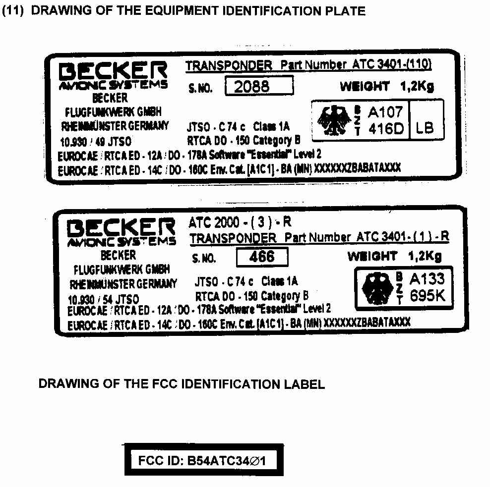
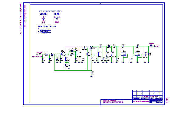
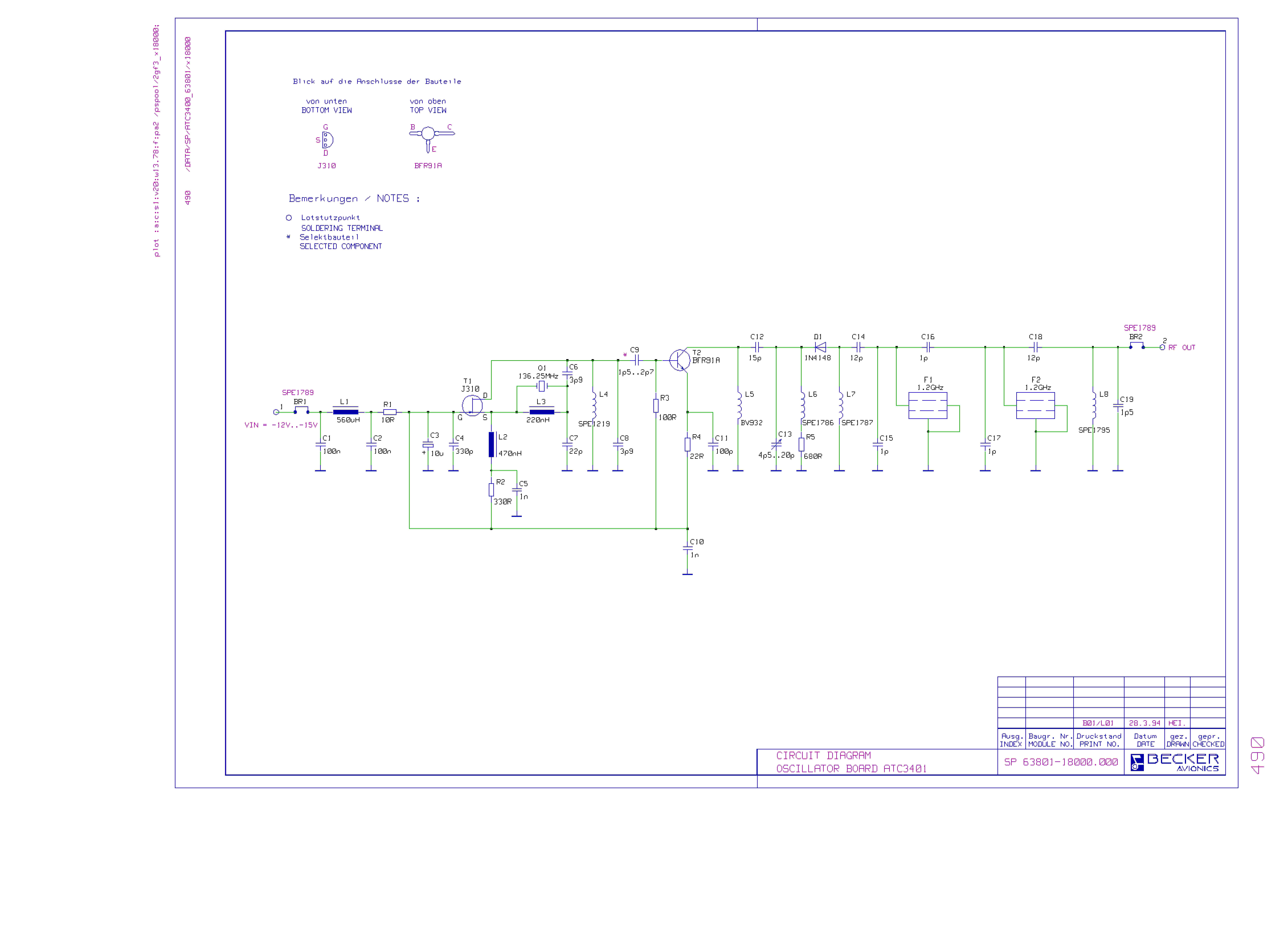
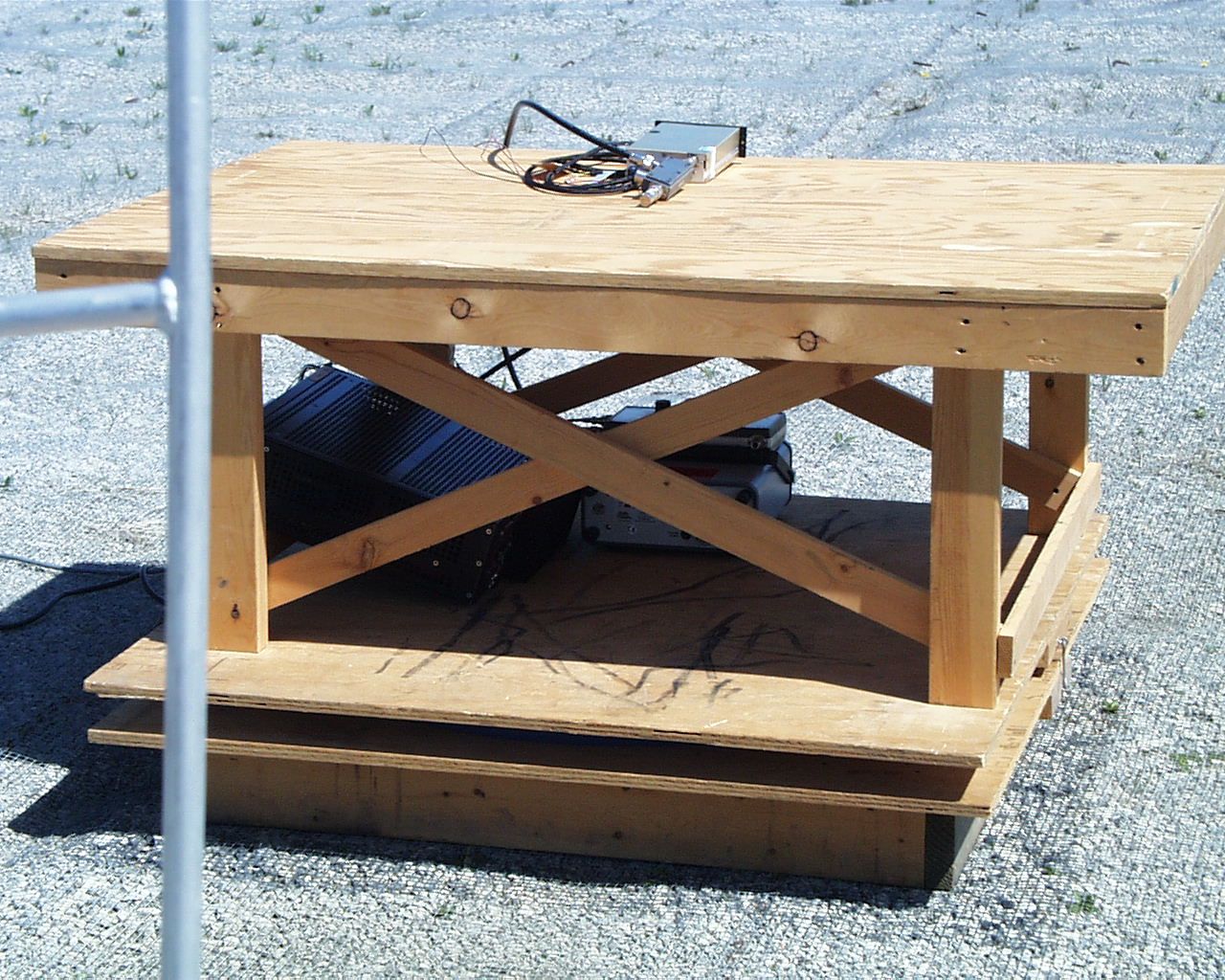
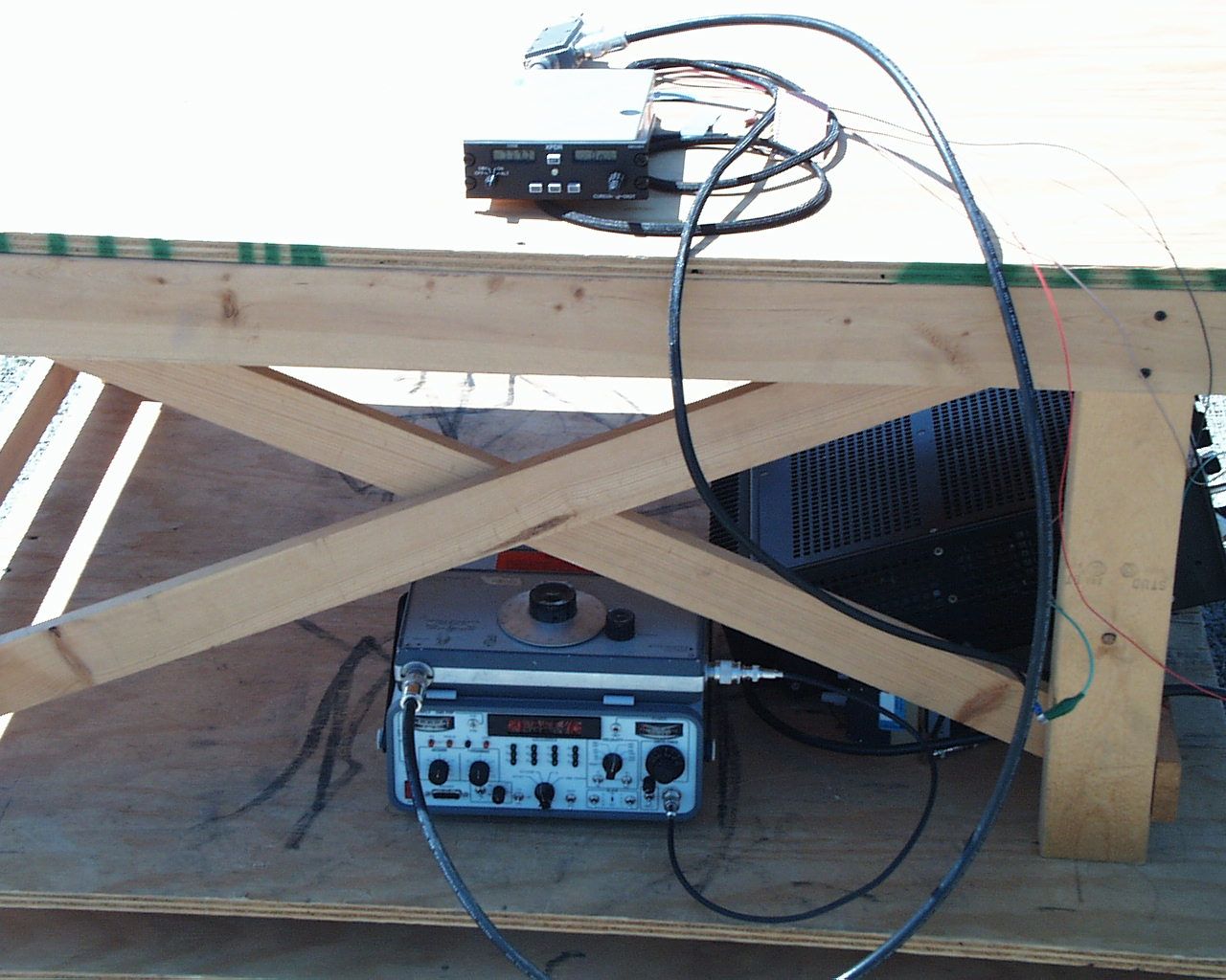
TEST REPORT for APPLICATION of CERTIFICATION For BECKER FLUNGFUNKWERK GMBH Baden Airpark Building B108 D-77836 Rheinmuenster Germany Phone: 49 7229 305 216 MODEL: ATC 3401 ATC 3401-(1)-R FREQUENCY: 1090 MHz FCC ID: B54ATC3401 Test Date: April 12, 1999 Certifying Engineer: Scot D. Rogers ROGERS LABS, INC. 4405 W. 259th Terrace Overland Park, Kansas 66210 Phone: (913)837-3214 FAX: (913)837-3214 This report shall not be reproduced except in full, without the written approval of the laboratory. This report must not be used by the client to claim product endorsement by NVLAP or any agency of the U.S. Government. NVLAP Accredited LaboratoryNVLAP Lab Code: 200087-0 ROGERS LABS, INC.BECKER FLUNGFUNKWERK GMBH 4405 W. 259th TerraceMODEL: ATC 3401 Louisburg, KS 66053Test #: 990412FCC ID: B54ATC3401 Phone/Fax: (913) 837-3214Test to: FCC Parts 2 & 87Page 2 of 27 Cert./BECKERATC3401a.doc July 19, 1999 TABLE OF CONTENTS FORWARD:3 LIST OF TEST EQUIPMENT3 2.1033(C)APPLICATION FOR CERTIFICATION4 2.1046RF POWER OUTPUT6 Measurements Required:6 Test Arrangement:7 Results:8 2.1047 MODULATION CHARACTERISTICS8 Measurements Required:8 Test Arrangement:9 Results:9 2.1049 OCCUPIED BANDWIDTH9 Measurements Required:9 Test Arrangement:10 Results:10 2.1051 SPURIOUS EMISSIONS AT ANTENNA TERMINALS11 Measurements Required:11 Test Arrangement:11 Results:13 2.1053FIELD STRENGTH OF SPURIOUS RADIATION14 Measurements Required:14 Test Arrangement:14 Results:16 2.1055 FREQUENCY STABILITY17 Measurements Required:17 Test Arrangement:17 Results:18 APPENDIX19 NVLAP Accredited LaboratoryNVLAP Lab Code: 200087-0 ROGERS LABS, INC.BECKER FLUNGFUNKWERK GMBH 4405 W. 259th TerraceMODEL: ATC 3401 Louisburg, KS 66053Test #: 990412FCC ID: B54ATC3401 Phone/Fax: (913) 837-3214Test to: FCC Parts 2 & 87Page 3 of 27 Cert./BECKERATC3401a.doc July 19, 1999 FORWARD: In accordance with the Federal Communications Code of Federal Regulations, dated October 1, 1998, Part 2 Subpart J, Paragraphs 2.907, 2.911, 2.913, 2.925, 2.926, 2.1031 through 2.1057; Part 87, Subchapter D, Paragraphs 87.131 through 87.147; and Report and Order FCC 98-58 the following is submitted: List of Test Equipment A Hewlett Packard 8591EM and or 8562A Spectrum Analyzer was used as the measuring device for the emissions testing. The analyzer settings used are described in the following table. Refer to Appendix for a complete list of Test Equipment. HP 8591EM SPECTRUM ANALYZER SETTINGS CONDUCTED EMISSIONS: RBWAVG. BW DETECTOR FUNCTION 9 kHz30 kHzPeak/Quasi Peak RADIATED EMISSIONS (30 – 1000 MHz): RBWAVG. BW DETECTOR FUNCTION 120 kHz300 kHzPeak/Quasi Peak HP 8562A SPECTRUM ANALYZER SETTINGS RADIATED EMISSIONS (1 – 40 GHz): RBWAVG. BW DETECTOR FUNCTION 1 MHz1 MHzPeak/Average ANTENNA CONDUCTED EMISSIONS: RBWAVG. BW DETECTOR FUNCTION 100 kHz300 kHzPeak NVLAP Accredited LaboratoryNVLAP Lab Code: 200087-0 ROGERS LABS, INC.BECKER FLUNGFUNKWERK GMBH 4405 W. 259th TerraceMODEL: ATC 3401 Louisburg, KS 66053Test #: 990412FCC ID: B54ATC3401 Phone/Fax: (913) 837-3214Test to: FCC Parts 2 & 87Page 4 of 27 Cert./BECKERATC3401a.doc July 19, 1999 2.1033(c)Application for Certification 1.Manufacturer:BECKER FLUNGFUNKWERK GMBH Baden Airpark Building B 108 D-77836 Rheinmuenster Germany 2.Identification:Model:ATC 3401 FCC I.D.: B54ATC3401 3.Refer to Exhibit for Installation and Operating Instructions Manual. 4.Emission Type:16M0M1D 5.Frequency Range:1090 MHz. 6.Operating Power Level: 250 W PEP (2.0 W Ave) Nominal Average Power = P o (PEP) X Duty Factor Duty Factor = 1200 RPS X 15 PR X (0.45 X 10 -6 ) PW Duty Factor = 0.0081 RPS = Replies Per Second PR = Pulse Reply Rate PW = Pulse Width 7.Max P o :400 W PEP. 8.Power into final amplifier: 855 Watts PEP (1500 V @ 0.57A). 9.Tune Up Procedure for Output Power: There are no tune-up procedures for ATC 3401. 10.Description of Circuitry and Devices Provided for Determining and Stabilizing Frequency, for Suppression of Spurious Radiation, Modulation and Power: NVLAP Accredited LaboratoryNVLAP Lab Code: 200087-0 ROGERS LABS, INC.BECKER FLUNGFUNKWERK GMBH 4405 W. 259th TerraceMODEL: ATC 3401 Louisburg, KS 66053Test #: 990412FCC ID: B54ATC3401 Phone/Fax: (913) 837-3214Test to: FCC Parts 2 & 87Page 5 of 27 Cert./BECKERATC3401a.doc July 19, 1999 The complete set of schematic diagrams for the Transponder ATC 3401 respectively ATC 3401-(1)-R are part of the equipment manuals. Please refer to these documents. The final transmit frequency is determined by a ¼ wavelength cavity resonator (MO5001). The cavity is tuned to the final frequency by means of a screw adjustment that changes the tank cavity capacity. NUMBERTYPE FUNCTION MO5001C0-2080ACavity Oscillator Description of the Circuits and Devices Used for Suppression of Spurious Radiation; For Limiting Modulation: The transmitter output is coupled to the antenna through a 4-section low pass filter. Description of the Circuits and Devices Used for Limiting of Modulation: The transponder uses the standard pulse format as required by ICAO, Annex 10 for both A and C modes of operation. A pulse train from the airborne unit is emitted after being interrogated by the ground unit. Each pulse has a width of 0.45 microseconds spaced 1.45 microseconds apart. Pulse train width between F1 and F2 is 20.3 microseconds. Rise time and fall time of the pulses is typically 0.050 microseconds. 11. FCC ID Label: NVLAP Accredited LaboratoryNVLAP Lab Code: 200087-0 ROGERS LABS, INC.BECKER FLUNGFUNKWERK GMBH 4405 W. 259th TerraceMODEL: ATC 3401 Louisburg, KS 66053Test #: 990412FCC ID: B54ATC3401 Phone/Fax: (913) 837-3214Test to: FCC Parts 2 & 87Page 6 of 27 Cert./BECKERATC3401a.doc July 19, 1999 Refer to Exhibit for FCC Label Identification. 12. Photographs of Equipment. Refer to Appendix of this Report. 13. Description of Digital Modulation: The modulator receives interrogation trigger pulses from the microprocessor. The pulses are applied to a differential comparator circuit. The output is then connected to the pulse transformer and then to …
Text truncated - open the document above for the full version.
Contact Information
Applicant
Frank Kistner
Technical Contact
Rogers Labs, Inc.Scot D Rogers
[email protected]913-837-3214
4405 West 259th Terrace · Louisburg, Kansas · United States
Non-Technical Contact
Rogers Labs, IncScot D Rogers
[email protected]913-837-3214
Test Firm
Rogers Labs, Inc.Scot Rogers
Technical Specifications
| # | Rule Parts | Frequency Range | Power Output | Emission | Tolerance |
|---|---|---|---|---|---|
| 1 | 87 | 1.09 GHz - 1.09 GHz | 250 W | 16M0M1D | 20.0000000000 ppm |
Other Applications from Becker Avionics GmbH
B54RT320911
Nov 03, 1999Aviation Communications Transceiver
Equipment Class
TNB - Licensed Non-Broadcast Station TransmitterB54CM4201-1
Aug 28, 1994TNB - Licensed Non-Broadcast Station Transmitter
Equipment Class
TNB - Licensed Non-Broadcast Station TransmitterB54AR4201
Aug 14, 1994TNB - Licensed Non-Broadcast Station Transmitter
Equipment Class
TNB - Licensed Non-Broadcast Station TransmitterB548RSAR3202
Oct 29, 1986The Part 74 references in your report are not valid.
Equipment Class
TNB - Licensed Non-Broadcast Station TransmitterB548RSNR3301
Sep 08, 1986CXX - Communications Rcvr for use w/ licensed Tx and CBs
Equipment Class
CXX - Communications Rcvr for use w/ licensed Tx and CBs