B66ACR-RLB35GlobalFix 406
ACR Electronics, Inc.
Click to zoom
Application Details
- Equipment Class
- GEP - 406 MHz EPIRB
- Date of Grant
- Aug 26, 2001
- Application Purpose
- Original Equipment
- Date of Application
- Jun 25, 2001
- Equipment Note
- GlobalFix 406
- Frequency Range
- 406.02500000 - 406.02500000
- Company
- ACR Electronics, Inc.
- Country
- United States
Documents & Files
Document Text
Text extracted from the exhibit documents filed with the FCC. Open a document above to read the original.
Users Manual
1 Y1-03-0157 Rev. T1 PRODUCT SUPPORT MANUAL Y1-03-0157 Rev. T1 GlobalFix TMTM 406 Emergency Position Indicating Radio Beacon FCC Type Accepted Product No. 2742 Cat. I Product No. 2744 Cat. II Owner Vessel Radio CallSign ACR Electronics, Inc. 5757 Ravenswood Road Fort Lauderdale, Fl 33312 +1(954) 981-3333 • Fax +1 (954) 983-5087 http://www.acrelectronics.com Email: [email protected] 2 Y1-03-0157 Rev. T1 * * * WARNING * * * THIS TRANSMITTER IS AUTHORIZED FOR USE ONLY DURING SITUATIONS OF GRAVE AND IMMINENT DANGER DELIBERATE MISUSE MAY INCUR A SEVERE PENALTY Advice to owners of Emergency Position Indicating Radio Beacons (EPIRBs) Registration of 406 MHz satellite EPIRB with the EPIRB Registration Section of the national authority* is mandatory because of the global alerting nature of the system. The information provided in the Registration Card is used only for rescue pur- poses. Fill in the owner registration card immediately upon completion of the sales transaction. Mail the Registration Card immediately. If the beacon is to enter service immediately, complete the Registration Card and fax the information to the national authority. The original card must still be mailed to the national authority* for hard-copy reference and filing. If the current owner is transferring the beacon to a new owner, the current owner is required to inform the national authority* by letter, facsimile or telephone, of the name and address of the new owner. The subsequent owner of the beacon is required to provide the national authority* with the information as shown on the owner Registration Card. This obligation transfers to all subsequent owners. *National Authority The term “national authority” appears throughout this manual. Wherever these words appear, reference is made to the government body responsible for EPIRB registration for the country in which the vessel is registered. The addresses for various national authorities can be found on the Registration Card appropriate for your vessel. The national authority in the U.S.A. is NOAA. The NOAA registration telephone no. is 1-888-212-7283 (toll free). Note: In the U.S.A. please use the enclosed FCC FORM 506 to modify your radio station license if necessary. For information on whether you need a radiostation license, call 1-888-CALLFCC (toll free) SECTION 1 - THE SYSTEM 23 Y1-03-0157 Rev. T1 22 Y1-03-0157 Rev. T1 3 Y1-03-0157 Rev. T1 1.1GENERAL 1.1.1This manual provides installation, operation and maintenance in- structions for the GlobalFix™ 406 Emergency Position Indicating Radio Beacon, hereinafter referred to as the Beacon. This section describes the characteristics and details of the Beacon System. The FCC authorizes the use of 406 MHz Radio Beacons by any ship that is also equipped with a VHF Ship Station. This will make the 406 MHz Radio Beacon available for use on most U.S. ships and boats. EPIRB carriage requirements are contained in USCG regulations. 1.2 PURPOSE 1.2.1The GlobalFix™ 406 Beacon provides distress alerting via radio transmission on 406 MHz to satellites of the COSPAS-SARSAT network and to the GEOSAR network that includes GPS latitude and longitude coordinates. 1.2.2The message transmitted by the GlobalFix™ 406 is unique for each EPIRB, which provides identification of the transmitter through computer access of registration files maintained by the National Oceanic and Atmospheric Administration or other national authority. It is the user’s responsibility to fill out and mail the enclosed registration form to the appropriate agency of the country under which the vessel is registered. US flagged vessels send the en- closed NOAA/NESDIS form to NOAA in the stamped envelope provided. For vessels registered in other countries, the GlobalFix™ 406 must be reprogrammed by an ACR authorized programming facility for the registered country. Remember, if your EPIRB is not registered, SAR Authorities do not know who you are, what type of vessel, your homeport, or where to contact anyone who might know anything about your situation. 1.2.3Once the GlobalFix™ 406 signal (406 MHz) is relayed through the COSPAS-SARSAT and/or GEOSAR network alert, Search and Res- cue (SAR) forces, they can converge on the GPS navigation position. When the GlobalFix™ 406 is used, SAR authorities can know your precise location immediately and speed up reaction time. The Glob- alFix™ 406 on board radio beacon transmitter (121.5 MHz) and high intensity xenon strobe light aid intermediate and short-range location. 1.2.4Product number 2742 GlobalFix™ 406 may be deployed and acti- vated automatically by the built-in hydrostatic float free release. 4 Y1-03-0157 Rev. T1 Once free from the release bracket, the GlobalFix™ 406 will automatically turn on if the water sensors are wet. 1.2.5Alternately, the GlobalFix™ 406 can be manually activated by lifting the thumb switch to a vertical position, sliding it toward the antenna and pushing back down to the opposite side of the EPIRB. Activating the beacon in this manner breaks off the "Activation Indicator Plastic Pin" and allows the switch to properly seat, showing the " z " symbol (ON). 1.2.6Self contained long life batteries with a five-year recommended replacement cycle provide power. See Factory Authorized Ser- vice Center for replacement (Section 4.0 – Maintenance). 1.2.7Self-test is initiated by momentarily lifting the thumb switch to a vertical position and holding it in this position for at least two seconds and at most 4 seconds. A beep and the simultaneous lighting of the red LED indicate the initiation of the test. The buzzer will beep an additional four times as the red LED lights simultaneously. The green LED will then light, followed by a flash of the strobe, indicating a successful test. During self-test, an actual satellite message is transmitted while certain key performance parameters are measured and recorded. The self- test message is modified to prevent the satellite from forwarding an alert message during self-…
Text truncated - open the document above for the full version.
Cover Letter(s)
July 18, 2001 Federal Communications Commission Equipment Approval Services P.O. Box 358315 Pittsburgh, PA 15251-5315 Attn:Mr. Frank Coperich Ref.: FCC ID: B66ACR-RLB-35 Subject:Request for Type Acceptance for Category I and II, 406 MHz Satellite EPIRB, Model ACR/RLB-35 (AKA - GlobalFix) Dear Mr. Frank Coperich: FCC Type Acceptance is hereby requested for ACR/RLB-35 Category 1 and Category 2 406 MHz Satellite EPIRBs manufactured by ACR Electronics, Inc. Category I and Category II RLB-35 EPIRBs are identical except for the name on the label. The Category 1 version is sold only with our automatic release mechanism. Category 2 is sold without mounting device. Our check in the amount of $640.00 is enclosed per your fee notice. Please mark on the Type Approval Certificate that both Category 1 and Category 2 EPIRBs are approved. The RLB-35 is submitted for Type Acceptance under FCC Rules and Regulations Parts 2 and 80. The ACR/RLB-35 406 MHz Satellite EPIRB complies with IMO Resolution A.694(17), IMO Resolution A.662(16) and IMO Resolution A.810(19). Please mark on the Type Approval Certificate that the ACR/RLB-35 is approved to IMO Resolution A.810(19). Please note that Circuit Diagrams ACR Y1-01-0635, ACR Y1-01-0636, ACR Y1-01- 0652 and ACR Y1-01-0653 are hereby submitted as Proprietary data (pursuant to 47 CFR 0.459 of the FCC Rules) with proprietary legend marked on the drawings. I certify that the information submitted with this application were developed at my direction and are true and correct to the best of my knowledge. Please call me directly for any additional information you may require regarding this matter. Very truly yours, John F. Flood Vice President/Engineering Encl., Form 731 Application Confirmation Form 159 Remittance Advice Check in the amount of $640.00 Type Acceptance Application Report Appendix 1 - Circuit Diagrams (ACR Y1-01-0635, Y1-01-0636, Y1-01-0652 and Y1-01-0653) Appendix 2 - Instruction Manual Appendix 3 - Assembly Drawings Appendix 4 - Label Drawings Appendix 5 - Photographs Appendix 6 - ACR Quality Assurance Manual (Submitted previously) Ref.. FCC ID B668L2 ACR-RLB-32
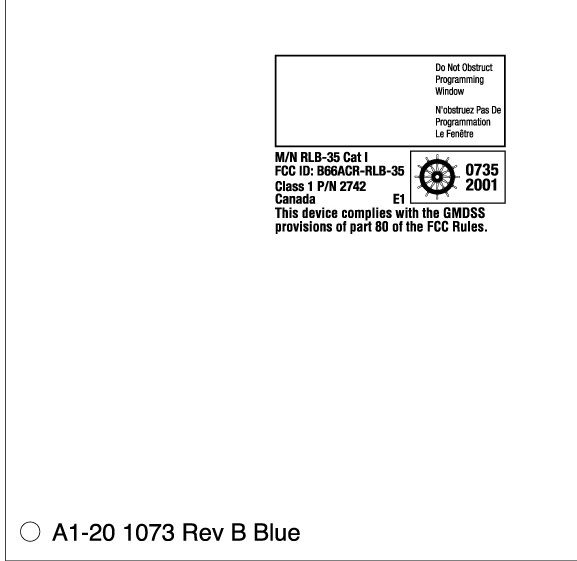
ID Label/Location Info
DRAWING NO. APVD. CHECKED DRAWN .005 .010 .030 DECIMALS TOLERANCES ON DIMENSIONS ARE IN INCHES UNLESS OTHERWISE SPECIFIED ANSI-A 1/64 + - .XXX + - .XX .X + - + - FRACTIONS 1/2 SOLIDWORKS + - ANGLES ENG. SCALE SIZE CODE IDENT. NO. DWG. NO. SHT REV REV ZONE DESCRIPTION REVISIONS REV SHEET APPROVED DATE THIS DOCUMENT AND THE DATA DISCLOSED HEREIN OR HEREWITH IS PROPERTY OF AND BELONGS TO ACR ELECTRONICS, INC. FT LAUDERDALE, FL. IT IS FURNISHED IN CONFIDENCE SOLELY FOR INFORMATIONAL PURPOSES. IT IS NOT TO BE REPRODUCED, USED OR DISCLOSED IN WHOLE OR IN PART TO ANYONE WITHOUT THE PERMISSION OF ACR. ACR ELECTRONICS, INC 5757 RAVENSWOOD RD. FT. LAUDERDALE FL 33312 18560 A 18560 LABEL, BOTTOM CASE, RLB-35 A1-20-1057- A M.P. 3/30/2001 1 4 A1-20-1057- 1 A ALL ANGLES ARE 90° OF A RELEASE PER ECO DENOTES REVISION CHANGE DENOTES DIMENSION PLUS DRAFT ANGLE DENOTES DIMENSION MINIUS DRAFT ANGLE + - DASH 1 TEXT DETAIL LAYOUT TOP DRAWING NO. SCALE SIZE CODE IDENT. NO. DWG. NO. SHT REV REV SHEET 18560 A 18560 A1-20-1057- A 2 4 A1-20-1057- 2 A OF DASH 2 TEXT DETAIL LAYOUT TOP DRAWING NO. SCALE SIZE CODE IDENT. NO. DWG. NO. SHT REV REV SHEET 18560 A 18560 A1-20-1057- A 3 4 A1-20-1057- 3 A OF DRAWING NO. SCALE SIZE CODE IDENT. NO. DWG. NO. SHT REV REV SHEET 18560 A 18560 A1-20-1057- A 1:1 4 4 A1-20-1057- 4 A OF 9.22 1.845 4X R.25 1 1 NOTES: 1. MATERIAL: .003 THICK, DEAD SOFT ALUMINUM ALUMAPRINT PHOTOMETAL PROCESS. 2. LABEL SHOULD ALWAYS BE POSITIONED WITH GLOBAL FIX LOGO TOWARD THE TOP PORTION OF LABEL AS SHOWN ON SHEETS 2 & 3. 3. FOR LABEL DESIGN LAYOUT & COLOR ARRANGEMENT, SEE ENGINEERING SAMPLE. 4. SLIT LABEL SO THAT IT MAY BE SEPARATED INTO TWO PARTS WHEN REMOVED FROM BACKING. 5. DASH INFORMATION: C L C L TOP 4.94 4X 1.0° DASH No.LABEL DESCRIPTION 1CAT. I, P/N 2742 2CAT. II, P/N 2744
ID Label/Location Info
DRAWING NO. APVD. CHECKED DRAWN .005 .010 .030 DECIMALS TOLERANCES ON DIMENSIONS ARE IN INCHES UNLESS OTHERWISE SPECIFIED ANSI-A 1/64 + - .XXX + - .XX .X + - + - FRACTIONS 1/2 SOLIDWORKS + - ANGLES ENG. SCALE SIZE CODE IDENT. NO. DWG. NO. SHT REV REV ZONE DESCRIPTION REVISIONS REV SHEET APPROVED DATE THIS DOCUMENT AND THE DATA DISCLOSED HEREIN OR HEREWITH IS PROPERTY OF AND BELONGS TO ACR ELECTRONICS, INC. FT LAUDERDALE, FL. IT IS FURNISHED IN CONFIDENCE SOLELY FOR INFORMATIONAL PURPOSES. IT IS NOT TO BE REPRODUCED, USED OR DISCLOSED IN WHOLE OR IN PART TO ANYONE WITHOUT THE PERMISSION OF ACR. ACR ELECTRONICS, INC 5757 RAVENSWOOD RD. FT. LAUDERDALE FL 33312 18560 A 18560 LABEL, BOTTOM CASE, RLB-35 A1-20-1057- A M.P. 3/30/2001 1 4 A1-20-1057- 1 A ALL ANGLES ARE 90° OF A RELEASE PER ECO DENOTES REVISION CHANGE DENOTES DIMENSION PLUS DRAFT ANGLE DENOTES DIMENSION MINIUS DRAFT ANGLE + - DASH 1 TEXT DETAIL LAYOUT TOP DRAWING NO. SCALE SIZE CODE IDENT. NO. DWG. NO. SHT REV REV SHEET 18560 A 18560 A1-20-1057- A 2 4 A1-20-1057- 2 A OF DASH 2 TEXT DETAIL LAYOUT TOP DRAWING NO. SCALE SIZE CODE IDENT. NO. DWG. NO. SHT REV REV SHEET 18560 A 18560 A1-20-1057- A 3 4 A1-20-1057- 3 A OF DRAWING NO. SCALE SIZE CODE IDENT. NO. DWG. NO. SHT REV REV SHEET 18560 A 18560 A1-20-1057- A 1:1 4 4 A1-20-1057- 4 A OF 9.22 1.845 4X R.25 1 1 NOTES: 1. MATERIAL: .003 THICK, DEAD SOFT ALUMINUM ALUMAPRINT PHOTOMETAL PROCESS. 2. LABEL SHOULD ALWAYS BE POSITIONED WITH GLOBAL FIX LOGO TOWARD THE TOP PORTION OF LABEL AS SHOWN ON SHEETS 2 & 3. 3. FOR LABEL DESIGN LAYOUT & COLOR ARRANGEMENT, SEE ENGINEERING SAMPLE. 4. SLIT LABEL SO THAT IT MAY BE SEPARATED INTO TWO PARTS WHEN REMOVED FROM BACKING. 5. DASH INFORMATION: C L C L TOP 4.94 4X 1.0° DASH No.LABEL DESCRIPTION 1CAT. I, P/N 2742 2CAT. II, P/N 2744
Operational Description
FCC ID: B66ACR-RLB-35 TYPE ACCEPTANCE APPLICATION FOR ACR/RLB-35 ACR ELECTRONICS, INC. 5757 RAVENSWOOD ROAD FORT LAUDERDALE, FL 33312 +1 (954) 981-3333 ⋅ ⋅⋅ ⋅ +1 (954) 983-5087 FAX FCC ID: B66ACR-RLB-35 ii TABLE OF CONTENTS 1.0 INTRODUCTION .................................................................................................................. 1 2.0 GENERAL INFORMATION REQUIRED FOR TYPE ACCEPTANCE ............................. 1 3.0 TECHNICAL DESCRIPTION............................................................................................... 1 4.0 REQUIRED TEST DATA...................................................................................................... 3 5.0 EQUIPMENT IDENTIFICATION......................................................................................... 4 6.0 PHOTOGRAPHS .................................................................................................................. 4 TABLE 1: FUNCTION OF ACTIVE ELEMENTS........................................................................ 5 FCC ID: B66ACR-RLB-35 3 1.0INTRODUCTION This report contains the required information and test data for Type Acceptance Approval for the ACR/RLB-35 406 MHz Emergency Position Indicating Radio Beacon (EPIRB). The ACR/RLB-35 meets all of the current FCC requirements for a 406 MHz EPIRB. The ACR/RLB-35 contains a battery pack consisting of three “D” size cells of Lithium Sulfur Dioxide chemistry. The battery pack will have a 5-year replacement cycle. The enclosure is made of high impact, corrosion resistant, ultra violet resistant plastic. The ACR/RLB-35 has an active internal GPS. The ACR/RLB-35 can be operated manually or with an automatic release bracket. Hence, there is a Cat I and Cat II for the ACR/RLB-35. Throughout this document, the ACR/RLB-35 may be referred to as the Beacon or EPIRB. 2.0 GENERAL INFORMATION REQUIRED FOR TYPE ACCEPTANCE Per FCC 2.1033 (c) 1)Name of Applicant:ACR Electronics, Inc. (manufacturer) Mailing Address:5757 Ravenswood Road Fort Lauderdale, FL 33312 2)FCC ID: B66ACR-RLB-35Model: RLB-35 Cat I Class 1 RLB-35 Cat II Class 1 3)Instruction Manual:APPENDIX 2 4) Type of Emission:406 MHz - 16K0G1D 121.5 MHz – 3K20A3X 5)Frequency Range:406.025 MHz ± .002 MHz 121.5 MHz ± .006 MHz 6)Range of Output Power:406 MHz - 5W ± 2dB 121.5 MHz - 50 mW ± 3 dB 7)Maximum Output Power (into 50 ohm):406 MHz - 7.9 W 121.5 MHz - 100 mW 8)DC Voltages and Currents:406 MHz - 8.2 V, 2.0 A @ U5-0635 121.5 MHz – 8.7 V, 11 mA @ Q3-0653 9)Tune-up Procedures: FCC ID: B66ACR-RLB-35 4 There is no tuning required for the 406 MHz 5 watt signal. There is no tuning required for the 121.5 MHz 0.05 watt signal. The antenna-matching network is tuned at 406 MHz by adjusting C38-0652 and L6-0652 and measuring the return loss into the antenna coupler network. The antenna matching network is tuned at 121.5 MHz by adjusting L3- 0652 and L4-0652 and measuring the return loss into the antenna coupler network. 10) Schematic Diagram:APPENDIX 1 Description of Circuitry (Refer to Schematic ACR Y1-01-0635, Y1-01-0636, Y1-01- 0652 and Y1-01-0653 (Appendix 1): The Beacon generates a phase modulated 406 MHz signal for transmission of the distress message. The 406 MHz carrier is frequency synthesized by a PLL, U4-0635. It is locked to an OCXO (U9-0636) to provide the high frequency stability required for the COSPAS- SARSAT system. The VCO is built around Q1-0636 in a common base configuration. The carrier is phase modulated by the phase lock loop filter of the PLL, U4-0635. U5-0636, Q3-0635 and U5-0635 then amplify the phase-modulated signal to provide 5W output at the antenna. The Beacon also has a 121.5 MHz radio beacon output. The 121.5 MHz is generated by a crystal (Y1-0653) controlled oscillator (Q1-0653) for frequency stability of better than ± 50 PPM over the full operating temperature range. Q2-0653 and Q3-0653 amplify the carrier to provide a nominal power output at the antenna of 50 mW. This signal is AM modulated by switching the 121.5 MHz drive signal on and off using Q5-0653 and U1- 0653. The modulation and other controls for the Beacon are generated by a microprocessor (U5-0652). This processor provides digital signals for both the 406 MHz and the 121.5 MHz modulations as well as for LED’s, a buzzer, strobe flashes, and other functions. The Beacon also incorporates a strobe light as required for 406 MHz EPIRBs. The RLB-35 has an internal GPS receiver that operates while the beacon is turned ON. This GPS receiver sends GPS navigation data to the microprocessor (U5-0652) for incorporation into the 406 beacon message. FCC ID: B66ACR-RLB-35 5 Description of Devices: TABLE 1: FUNCTION OF ACTIVE ELEMENTS DESIGNATORFUNCTION U1,2-0635VOLT REG., MIC2954 U3-0635VOLT REG., LP2980 U5-0635PWR AMP., M687321 Q1,7,8,9-0635XSTR SWITCH, MMBT2907 Q2,4,5-0635XSTR SWITCH, MMBT3904 Q3-0635RF AMP, NE85633 Q6-0635P-FET,SWITCH, RFD1505SM U1A,B;U2A,B-0636D FLIP-FLOP, MC74VHC74A U3,7,8-0636XOR, NC7SZ86 U4A,B,C,D-0636AND, MC74VHC00A U5-0636RF AMP, HP2111 U6-0636PRESCALER MC12080D U9-0636OVENIZED OSCILLATOR Q1-0636VCO, MMBR521LT U1-0652DUAL NAND GATE U2-0652VOLT REG, MAX667 U3-0652VOLT SUPERVISOR U4-0652VOLT REG, MIC5201 U5-0652MICROPROCESSOR, PIC16LF877 U6-0652IR TRANSCEIVER, HSDL3610 U7-0652GPS RECEIVER, SWIFT A1 Q1-0652XSTR SWITCH, MMBT2222A FCC ID: B66ACR-RLB-35 6 DESIGNATORFUNCTION Q2,6,7,9-0652XSTR SWITCH, BC850C Q3-0652FET SWITCH, ME8PO6 Q4-0652XSTR SWITCH, FMMT718 Q5,-0652XSTR SWITCH, MMBT3904 Q8-0652XSTR SWITCH, MMBT3906 Q10,11-0652FET SWITCH, 2N7002 CR1-0652SCR, CMPS5064 CR2-0652RECTIFIERS, CMPD2004S CR3-0652DIODES, BAV-74 D3-0652DIODE, HSMS2800 U1-0653RF SWITCH U2-0653XOR GATE Q1-0653RF OSCILLATOR Q2-0653RF AMP Q3-0653RF P.A. Q4,5,-0653BIAS Q12-0653LIMITER Circuitry for Determining and Stabilizing Frequency: The 406.025 MHz carrier is phase locked to a high stability oven controlled oscillator as required for the COSPAS-SARSAT system. The 121.5 MHz carrier is generated by a crystal cont…
Text truncated - open the document above for the full version.
Operational Description
FCC ID: B66ACR-RLB-35 TYPE ACCEPTANCE APPLICATION FOR ACR/RLB-35 ACR ELECTRONICS, INC. 5757 RAVENSWOOD ROAD FORT LAUDERDALE, FL 33312 +1 (954) 981-3333 ⋅ ⋅⋅ ⋅ +1 (954) 983-5087 FAX FCC ID: B66ACR-RLB-35 ii TABLE OF CONTENTS LIST OF APPENDICES...................................... ........... .................... ........... ........... ........ ii 1.0 INTRODUCTION .................................................................................................................. 1 2.0 GENERAL INFORMATION REQUIRED FOR TYPE ACCEPTANCE ............................. 1 3.0 TECHNICAL DESCRIPTION............................................................................................... 1 4.0 REQUIRED TEST DATA...................................................................................................... 3 5.0 EQUIPMENT IDENTIFICATION......................................................................................... 4 6.0 PHOTOGRAPHS .................................................................................................................. 4 TABLE 1: FUNCTION OF ACTIVE ELEMENTS........................................................................ 5 FCC ID: B66ACR-RLB-35 3 LIST OF APPENDICES Appendix 1 .....................Circuit Diagrams ................................. (ACR Y1-01-0635, ........................................ ............................................................ Y1-01-0636, ........................................ ............................................................ Y1-01-0652, ........................................ ............................................................ Y1-01-0653) Appendix 2 .....................Instruction Manual.............................. (ACR Y1-03-0157) Appendix 3 .....................Assembly Drawings : ACR A3-06-2200................................ Final Assy, Global 406 ACR A3-06-2201................................ Elect. Sub Assy ACR A3-06-2202................................ Top Case Assy Appendix 4 .....................Label Drawings Appendix 5 .....................Photographs Appendix 6 .....................Independent Lab Test Report (Intespace) Appendix 7 .....................ACR Quality Assurance Manual - FCC ID: B66ACR-RLB-35 4 1.0INTRODUCTION This report contains the required information and test data for Type Acceptance Approval for the ACR/RLB-35 406 MHz Emergency Position Indicating Radio Beacon (EPIRB). The ACR/RLB-35 meets all of the current FCC requirements for a 406 MHz EPIRB. The ACR/RLB-35 contains a battery pack consisting of three “D” size cells of Lithium Sulfur Dioxide chemistry. The battery pack will have a 5-year replacement cycle. The enclosure is made of high impact, corrosion resistant, ultra violet resistant plastic. The ACR/RLB-35 has an active internal GPS. The ACR/RLB-35 can be operated manually or with an automatic release bracket. Hence, there is a Cat I and Cat II for the ACR/RLB-35. Throughout this document, the ACR/RLB-35 may be referred to as the Beacon or EPIRB. 2.0 GENERAL INFORMATION REQUIRED FOR TYPE ACCEPTANCE Per FCC 2.1033 (c) 1)Name of Applicant:ACR Electronics, Inc. (manufacturer) Mailing Address:5757 Ravenswood Road Fort Lauderdale, FL 33312 2)FCC ID: B66ACR-RLB-35Model: RLB-35 Cat I Class 1 RLB-35 Cat II Class 1 3)Instruction Manual:APPENDIX 2 4) Type of Emission:406 MHz - 16K0G1D 121.5 MHz – 3K20A3X 5)Frequency Range:406.025 MHz ± .002 MHz 121.5 MHz ± .006 MHz 6)Range of Output Power:406 MHz - 5W ± 2dB 121.5 MHz - 50 mW ± 3 dB 7)Maximum Output Power (into 50 ohm):406 MHz - 7.9 W 121.5 MHz - 100 mW 8)DC Voltages and Currents:406 MHz - 8.2 V, 2.0 A @ U5-0635 121.5 MHz – 8.7 V, 11 mA @ Q3-0653 9)Tune-up Procedures: FCC ID: B66ACR-RLB-35 5 There is no tuning required for the 406 MHz 5 watt signal. There is no tuning required for the 121.5 MHz 0.05 watt signal. The antenna-matching network is tuned at 406 MHz by adjusting C38-0652 and L6-0652 and measuring the return loss into the antenna coupler network. The antenna matching network is tuned at 121.5 MHz by adjusting L3- 0652 and L4-0652 and measuring the return loss into the antenna coupler network. 10) Schematic Diagram:APPENDIX 1 Description of Circuitry (Refer to Schematic ACR Y1-01-0635, Y1-01-0636, Y1-01- 0652 and Y1-01-0653 (Appendix 1): The Beacon generates a phase modulated 406 MHz signal for transmission of the distress message. The 406 MHz carrier is frequency synthesized by a PLL, U4-0635. It is locked to an OCXO (U9-0636) to provide the high frequency stability required for the COSPAS- SARSAT system. The VCO is built around Q1-0636 in a common base configuration. The carrier is phase modulated by the phase lock loop filter of the PLL, U4-0635. U5-0636, Q3-0635 and U5-0635 then amplify the phase-modulated signal to provide 5W output at the antenna. The Beacon also has a 121.5 MHz radio beacon output. The 121.5 MHz is generated by a crystal (Y1-0653) controlled oscillator (Q1-0653) for frequency stability of better than ± 50 PPM over the full operating temperature range. Q2-0653 and Q3-0653 amplify the carrier to provide a nominal power output at the antenna of 50 mW. This signal is AM modulated by switching the 121.5 MHz drive signal on and off using Q5-0653 and U1- 0653. The modulation and other controls for the Beacon are generated by a microprocessor (U5-0652). This processor provides digital signals for both the 406 MHz and the 121.5 MHz modulations as well as for LED’s, a buzzer, strobe flashes, and other functions. The Beacon also incorporates a strobe light as required for 406 MHz EPIRBs. The RLB-35 has an internal GPS receiver that operates while the beacon is turned ON. This GPS receiver sends GPS navigation data to the microprocessor (U5-0652) for incorporation into the 406 beacon message. FCC ID: B66ACR-RLB-35 6 Description of Devices: TABLE 1: FUNCTION OF ACTIVE ELEMENTS DESIGNATORFUNCTION U1,2-0635VOLT REG., MIC2954 U3-0635VOLT REG., LP2980 U5-0635PWR AMP., M687321 Q1,7,8,9-0635XSTR…
Text truncated - open the document above for the full version.
Parts List/Tune Up Info
OF ENG. APVD. DRAWN CHECKED THIS DOCUMENT AND THE DATA DISCLOSED HEREIN OR HEREWITH IS PROPERTY OF AND BELONGS TO ACR ELECTRONICS, INC. FT LAUDERDALE, FL. IT IS FURNISHED IN CONFIDENCE SOLELY FOR INFORMATIONAL PURPOSES. IT IS NOT TO BE REPRODUCED, USED OR DISCLOSED IN WHOLE OR IN PART TO ANYONE WITHOUT THE PERMISSION OF ACR. 7 A 8 B 65 7 C D 865 SIZE LIST OF MATERIALS OR PARTS LIST 4 3 ANSI-DSOLIDWORKS 2 ALL ANGLES ARE 90° TOLERANCES ON DIMENSIONS ARE IN INCHES UNLESS OTHERWISE SPECIFIED: .XX .XXX .X FRACTIONS + - 1/64 .010 .005 + - + - DECIMALS .030+ - ANGLES 1/2 + - O SCALE 1 SHEET CODE IDENT. NO. DRAWING NO. REV A B DESCRIPTION ZONE REV 4 3 DWG. NO. DATE APPROVED C D REVISIONS SHTREV 1 18560 5757 RAVENSWOOD RD. FT. LAUDERDALE FL 33312 ACR ELECTRONICS, INC 18560 D M.P.6/26/2001 FINAL ASSEMBLY, GLOBALFIX 406 / RLB-35 A3-06-2200- 1:211 A A3-06-2200- A 1 ARELEASE PER ECO DENOTES REVISION CHANGE DENOTES DIMENSION PLUS DRAFT ANGLE DENOTES DIMENSION MINIUS DRAFT ANGLE + - 2 1 4 5 6 7 4X 9 8 NOTES: 1. BEACON WEIGHT: 85010 GRAMS 2. CONNECT CONNECTOR FROM BTRY PACK ASSY. (ITEM 5 ) TO PCB CONNECTOR LOCATED ON TOP CASE ASSY.(ITEM 2 OR 12) BEFORE SEALING UNIT. 3. ADD A SMALL AMOUNT OF LUBRICANT (ITEM 10) TO THE THREADS OF SCREWS (ITEM 8) AND O-RING (ITEM 6). 4. TORQUE SCREWS (ITEM 8) TO 3 IN/LB. 5. FILL IN EXPIRATION DATE ON BTRY PACK ASSY. WARNING LABEL WITH A DATE OF 5 YEARS & 4 MONTHS FROM DATE OF MANUFACTURING. 6. WATER TEST PER Y1-02-0271 10 1 1 1 OR 12 OR 13 ISOMETRIC VIEWS SCALE 1:3 16.36 8.96 4.80 3.67 8.15 OVERALL DIMESIONS 1 -13A1-15-0262-2BOTTOM CASE, CAT. II 1 -12A3-06-2201-2TOP CASE, ELECTRICAL ASSY., CAT. II REFREF11Y1-02-0271 LEAKAGE TEST PROCEDURE 1110A2-05-0087LUBRICANT, SILICONE, (SUPER-LUBE) 119A3-06-2085LANYARD, ASSY 448MS51957-44SCREW, PH, #8-32 x .4375L 227 A1-18-1490 PAD, BATTERY 116A1-05-0001-38O-RING, #2-245, SILICONE 115A3-06-1793-ASSY., BATTERY PACK 114A3-06-1898-4BALLAST ASSEMBLY, 160g -12A3-06-2201-1TOP CASE, ELECTRICAL ASSY., CAT. I - 11A1-15-0262-1BOTTOM CASE, CAT. I DASH 2 QTY. DASH 1 QTY. ITEM NO.PART OR IDENTIFYING NO.NOMENCLATURE OR DESCRIPTIONMATERIAL & SPECIFICATION LIST OF MATERIALS OR PARTS LIST DASH INFORMATION DASH No.DESCRIPTION 1RLB-35, CAT. I 2RLB-35, CAT. II
Parts List/Tune Up Info
OF DRAWN THIS DOCUMENT AND THE DATA DISCLOSED HEREIN OR HEREWITH IS PROPERTY OF AND BELONGS TO ACR ELECTRONICS, INC. FT LAUDERDALE, FL. IT IS FURNISHED IN CONFIDENCE SOLELY FOR INFORMATIONAL PURPOSES. IT IS NOT TO BE REPRODUCED, USED OR DISCLOSED IN WHOLE OR IN PART TO ANYONE WITHOUT THE PERMISSION OF ACR. 7 A 8 B 65 7 C D 865 SIZE LIST OF MATERIALS OR PARTS LIST 4 3 ANSI-DSOLIDWORKS 2 ALL ANGLES ARE 90° TOLERANCES ON DIMENSIONS ARE IN INCHES UNLESS OTHERWISE SPECIFIED: .XX .XXX .X FRACTIONS + - 1/64 .010 .005 + - + - DECIMALS .030+ - ANGLES 1/2 + - O SCALE 1 SHEET CODE IDENT. NO. DRAWING NO. REV A B DESCRIPTION ZONE REV 4 3 DWG. NO. DATE APPROVED C D REVISIONS SHTREV 1 18560 5757 RAVENSWOOD RD. FT. LAUDERDALE FL 33312 ACR ELECTRONICS, INC 18560 D M.P.6/26/2001 ELECT. SUB-ASSEMBLY, GLOBALFIX 406/RLB-35 A3-06-2201- 1:211 A A3-06-2201- A 1 ARELEASE PER ECO DENOTES REVISION CHANGE DENOTES DIMENSION PLUS DRAFT ANGLE DENOTES DIMENSION MINIUS DRAFT ANGLE + - 7 8 10 11 6 5 9 1 2 3 4 4x OR 12 B B (REF) NOTES: 1. ATTACH ANTENNA ASSY. (ITEM 2 ) TO TOP CASE ASSY. (ITEM 1OR 12). 2. INSERT PCB ASSY. (ITEM 4) INTO TOP CASE ASSY. (ITEM 1OR 12) AND ATTACH WITH ITEMS 5 & 6. 3. CONNECT PCB ASSY. TRANSMITTER (ITEM 7) & PCB ASSY. HOMER BOARD (ITEM 8) TO PCB ASSY. I/O BOARD (ITEM 4) AS SHOWN. 4. PEEL OFF PAPER FROM PAD (ITEM 9) AND ATTACH TO BOTTOM INSIDE OF CLAMP (ITEM 10). 5. INSERT CLAMP (ITEM 10) INTO TOP CASE ASSY. DURING INSERTION, MAKE SURE HOMER & TRANSMITTER PCB ASSEMBLIES ALIGN WITH AND SLIDE THROUGH GROOVES INSIDE CLAMP. ONCE FULLY INSERTED, ATTACH CLAMP USING ITEM 11. 6. PULL WIRES 1 & 2 AROUND CLAMP AND SOLDER TO TERMINALS AS SHOWN. SECTION B-B SCALE 1 : 1 5 6 (REF) (REF) 11 WIRE 2 WIRE 1 WIRE 2 WIRE 1 ISOMETRIC VIEWS SCALE 1:2 1 -12A3-06-2202-2TOP CAP ASSY., GLOBALFIX 406/RLB-35, CAT. II 1111 MS24626-18 SCREW, SELF-TAPPING, PH, 1110A1-18-1785 CLAMP 119A1-25-0108PAD, PRESSURE WITH ADHESIVE 118A3-07-0265-1PCB ASSY., H.P., HOMER BOARD 447A3-07-0240-1PCB ASSY., H.P., 406 MHz TRANSMITTER 116MS51957-27SCREW, PH, 6-32, 5/16 LG 115MS35335-58WASHER, EXTERNAL TOOTH, #6 114A3-07-0264-1PCB ASSY., H.P., I/O BOARD 113A2-05-0067-0162REFLECTIVE SHEETING, 2" WIDE 1.625 CUT LENGTH 112A3-06-1791-1ANTENNA ASSEMBLY - 11A3-06-2202-1TOP CAP ASSY., GLOBALFIX 406/RLB-35, CAT. I DASH 2 QTY. DASH 1 QTY. ITEM NO. PART OR IDENTIFYING NO. NOMENCLATURE OR DESCRIPTIONMATERIAL & SPECIFICATION LIST OF MATERIALS OR PARTS LIST DASH INFORMATION DASH No.DESCRIPTION 1RLB-35, CAT. I 2RLB-35, CAT. II
Parts List/Tune Up Info
OF ENG. APVD. DRAWN CHECKED THIS DOCUMENT AND THE DATA DISCLOSED HEREIN OR HEREWITH IS PROPERTY OF AND BELONGS TO ACR ELECTRONICS, INC. FT LAUDERDALE, FL. IT IS FURNISHED IN CONFIDENCE SOLELY FOR INFORMATIONAL PURPOSES. IT IS NOT TO BE REPRODUCED, USED OR DISCLOSED IN WHOLE OR IN PART TO ANYONE WITHOUT THE PERMISSION OF ACR. 7 A 8 B 65 7 C D 865 SIZE LIST OF MATERIALS OR PARTS LIST 4 3 ANSI-DSOLIDWORKS 2 ALL ANGLES ARE 90° TOLERANCES ON DIMENSIONS ARE IN INCHES UNLESS OTHERWISE SPECIFIED: .XX .XXX .X FRACTIONS + - 1/64 .010 .005 + - + - DECIMALS .030+ - ANGLES 1/2 + - O SCALE 1 SHEET CODE IDENT. NO. DRAWING NO. REV A B DESCRIPTION ZONE 4 3 DWG. NO. DATE APPROVED C D REVISIONS 18560 5757 RAVENSWOOD RD. FT. LAUDERDALE FL 33312 ACR ELECTRONICS, INC 18560 D M.P.6/26/2001 TOP CASE ASSEMBLY, GLOBALFIX 406/RLB-35 A3-06-2202- 1:111 A A3-06-2202- A 1 ARELEASE PER ECO DENOTES REVISION CHANGE DENOTES DIMENSION PLUS DRAFT ANGLE DENOTES DIMENSION MINIUS DRAFT ANGLE + - 13 1 7 6 5 14 10 11 9 8 2 3 NOTES: 1. ULTRASONICALLY WELD INSERTS (ITEM 2) TO TOP CAP (ITEM 1 OR 15) IN PLACES WHERE SHOWN. 2. APPLY COPPER TAPE (ITEM 14) TO INNER WALLS OF TOP CASE . MAKE SURE TO APPLY EXCESS TAPE OVER SCREW BOSSES AS SHOWN IN TAPE DETAIL. 4 12 15OR 2X B B 4X SECTION B-B 9 10 11 (REF) (REF) (REF) 2X 14 (REF) TAPE DETAIL ISOMETRIC VIEWS SCALE 1:2 1 -15A1-18-1780-2CASE, TOP, PAD PRINTED, CAT. II 2214A2-05-0024-4TAPE, COPPER, 2" WIDE 3" CUT LENGTH 1113A1-17-1298ANTENA BASE 1112A1-05-0001-25O-RING, SILICONE, .143 X .280 1111MS35335-58WASHER, EXTERNAL TOOTH…
Text truncated - open the document above for the full version.
Contact Information
Applicant
Dan Stankovic(Director, Certification and Test)
Technical Contact
ACR Electronics, Inc.Cal Havens
[email protected]954 981-3333
5757 Ravenswood Road · Ft. Lauderdale, Florida · United States
Non-Technical Contact
ACR Electronics, IncJohn F Flood
[email protected]954 981-3333
Technical Specifications
| # | Rule Parts | Frequency Range | Power Output | Emission | Tolerance |
|---|---|---|---|---|---|
| 2 | 80.1101(c)(5) | 406.025 MHz - 406.025 MHz | 5 W | 16K0G1D | 0.0005 % |
Other Applications from ACR Electronics, Inc.

B66ACR-RLB44
Jan 25, 2023Marine AIS Transceiver with EPIRB
Equipment Class
AIS - Automatic Identification Systems
B66ACR-PLB-350
Aug 04, 2009Personal Locator Beacon
Equipment Class
PLB - Personal Locator Beacons
B66ACR-AIS-300
Oct 07, 2008Class B Automatic Identification System
Equipment Class
AIS - Automatic Identification Systems
B66ACR-PLB-300
Jan 11, 2007Personal Locator Beacon
Equipment Class
PLB - Personal Locator Beacons
B66ACR-RLB-33S
Dec 27, 2004Ship Security Alert System
Equipment Class
SSA - Ship Security Alert Systems (SSAS)