B7JDJCRVSIIRadar Velocity Sensor
Dickey John Corporation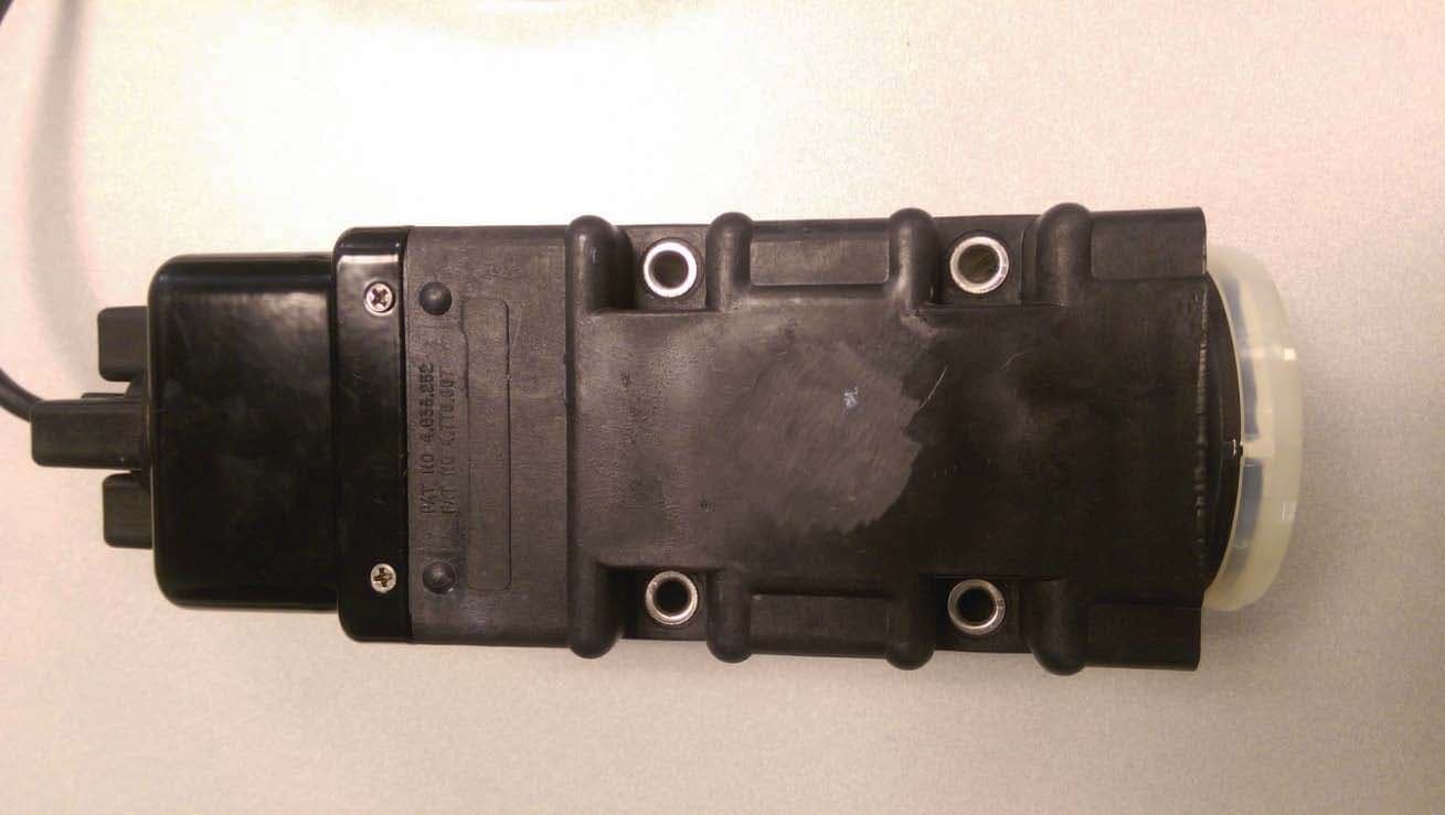
Click to zoom
Application Details
- Equipment Class
- FDS - Part 15 Field Disturbance Sensor
- Date of Grant
- Oct 26, 2015
- Application Purpose
- Original Equipment
- Date of Application
- Oct 26, 2015
- Equipment Note
- Radar Velocity Sensor
- Frequency Range
- 24125.00000000 - 24125.00000000
- Company
- Dickey John Corporation
- Country
- United States
Documents & Files
Document Text
Text extracted from the exhibit documents filed with the FCC. Open a document above to read the original.
Users Manual
INSTALLATION INSTRUCTIONS DJRVS II Radar Velocity Sensor 11001-1208C-201510 1 RADAR II VELOCITY SENSOR COMPLIANCE This equipment has been tested and found to comply with the limits for a Class B digital device pursuant to part 15 of the FCC Rules. These limits are designed to provide reasonable protection against harmful interference in a residential installation. This equipment generates, uses, and can radiate radio frequency energy and, if not installed and used in accordance with the instructions, may cause harmful interference to radio communications. However, there is no guarantee that interference will not occur in a particular installation. If this equipment does cause harmful interference to radio or television rec eption which can be determined by turning the equipment off and on, the user is encouraged to try to correct the interference by one or more of the following measures: – Reorient or relocate the receiving antenna – Increase the separation between the equipment and receiver – Connect the equipment into an outlet on a circuit different from th at to which the receiver is connected – Consult the dealer or an experienced radio/TV technician for help DISCLAIMER DICKEY-john reserves the right to make engineering refinements or procedural changes that may not be reflected in this manual. Material included in this manual is for informational purposes and is subject to change without notice. INSTALLATION INSTRUCTIONS DJRVS II Radar Velocity Sensor 11001-1208C-201510 2 INSTALLATION INSTRUCTIONS 3 DICKEY-john DjRVS ll RADAR VELOCITY SENSOR DjRVS ll SENSOR KIT 1.DjRVS ll Sensor 2.Installation Instructions PLATE MOUNTING BRACKET Customer fabricated mounting plate (see dimensional drawing in Section A. PLATE MOUNTING BRACKET). DjRVS ll MOUNTING BRACKET KIT 1.Mounting Bracket 2.U-Bolts 1 1/8" x 2" x 1/4 - 20 (2) 3.1/4" Split Ring Lockwashers (8) 4.1/4" Flatwashers (8) 5.1/4 - 20 x 4" Bolts (4) 6.1/4 - 20 Nuts (8) 11001-1208C-201510 ® DjRVS ll “L” PIPE MOUNTING BRACKET KIT 1.“L” Pipe Mounting Bracket 2. 3/8 - 16 x 1 1/2” Bolts (2) 3. 3/8 Split Ring Lockwashers (2) 4. 3/8 Nuts (2) The DjRVS ll can be mounted several ways. The mounting kits are designed to give the user the option of fabricat- ing his own mounting bracket, retrofit- ting to an existing DjRVS I “L” pipe mounting bracket, or using “L” shaped pipe mounting bracket kits purchased from DICKEY-john for new installations. SELECTING MOUNTING LOCATION 1. Refer to the above illustration and park the vehicle on level ground. This is necessary in order to install the sensor at the proper angle with re- spect to ground. IMPORTANT: Changes or modifications to the RVS ground speed sensor not expressly approved by DICKEY-john Corporation could void the user's authority to operate the equipment. ww INSTALLATION INSTRUCTIONS 4 2. The following list describes some of the precautions which should be fol- lowed when selecting a mount- ing location. a. The face of the sensor will have an unobstructed view of the ground. The area that must remain unob- structed is cone shaped from the face of the sensor to the ground as shown. The pattern of the sensor signal on the ground is oval shaped due to the installation angle. The size of the ovaI pattern is depen- dent on the sensor height above ground. The following is the pattern size for the indicated height SENSORPATTERN HEIGHTSIZE (OVAL) 18 inches18.8 x 12.7 inches 24 inches24.17 x 17.2 inches 48 inches31.0 x 25.6 inches b. Fluids do not drip on sensor face area. c. The sensor is away from all heat sources. d. The sensor face or rear metal housing does not touch the vehicle. e. The sensor is protected from stubble and debris. f. It is recommended that the sensor be installed facing the rear of the ve- hicle. NOTE: There may be instances where the sensor wiII have to be ori- ented facing forward, but rear facing is preferred to offer more physical pro- tection to the radar sensor. g. The sensor mounting location must have a minimal amount of vibration; excessive vibration may cause erro- neous MPH readings with the vehicle stationary. NOTE: Care must be exercised when selecting mounting heights of more than four feet. The sensor must have an un- obstructed cone shaped view of the ground. If a vehicle tire, hose, or liquid line is within the cone shaped area, erroneous readings may result INSTALLATION INSTRUCTIONS 5 A. PLATE MOUNTING BRACKET (fabricated by user) 1.Shown above is a dimensional draw- ing of the plate mounting bracket, which may be fabricated by the in- staller. The mounting plate must be made out of 5/16 inch steel plate. IMPORTANT: Using steel plate less than 5/16 inch may allow the radar velocity sensor to vibrate which could cause erroneous MPH(kph) readings. Refer to the above illustration and make the flat plate mounting bracket as shown. NOTE: The most critical dimensions are the placement of the four Radar I I Sen- sor mounting holes. However, these holes may be ovaled out if they are not drilled in the exact location. Suggested mounting hardware is as fol- lows. 1. 3/8-16 x 1-1/2" Bolts (2) 2. 3/8 Split Ring Lockwashers (2) 3. 3/8 Nuts (2) 4. 1/4 - 20 x 4" Bolts, SST (4) 5. 1/4 Flatwashers, SST (8) 6. 1/4 - 20 Nuts, SST (4) 7. 1/4 Split Ring Lockwashers, SST (4) 8. 9/32" x 1/2" x 9/10" Spacers (4) (Dj-Part No. 45640-4110) IMPORTANT: MAKE CERTAIN THE MOUNT- ING PLATE DOES NOT EXTEND PAST THE SENSOR HOUSING. METAL BESIDE THE FACE AREA CAN CAUSE IMPROPER OPERATION OF THE SENSORS. IMPORTANT: MAKE CERTAIN THAT THE METAL REAR HOUSING OF THE SENSOR DOES NOT COME IN CONTACT WITH THE VEHICLE FRAME OR THE MOUNTING BRACKET. Such contact can cause erratic readings by introducing electri- cal noise into the sensor. Under certain circumstances, such contact may cause electrical damage to the sensor. INSTALLATION INSTRUCTIONS 6 2. Refer to the above illustration and install the DjRVS ll Sensor on the flat plate mounting bracket as shown with the enclosure seam on the side. Make certain spa…
Text truncated - open the document above for the full version.
Cover Letter(s)
DICKEY-john Corporation 5200 DICKEY-john Road Auburn, IL 62615 Phone: 217/438-3371 www.dickey-john.com 19 October 2015 TUV SUD BABT FCB Octagon House, Segensworth Road, Fareham, Hampshire, PO15 5RL RE: Authority to Act as Agent FCC ID: B7JDJCRVSII IC ID: 5682A-DJCRVSII Model(s): 44587(12V) & 44587(24V) Dear Sir or Madam, We, DICKEY-john Corporation, 5200 DICKEY-john Rd, Auburn IL 62615, hereby authorize Juan Manuel Gonzalez, at TUV SUD America Inc., 10040 Mesa Rim Road, San Diego, CA 92121,Tel. 858-678-1400, to act as our agent in all matters relating to applications for equipment authorization, including the signing of all documents relating to these matters. This authorization expires on 19 October 2017. Sincerely, Name: Barry C. Mears Title: Senior Staff Engineer
Cover Letter(s)
DICKEY-john Corporation 5200 DICKEY-john Road Auburn, IL 62615 Phone: 217/438-3371 www.dickey-john.com 19 October 2015 TUV SUD BABT TCB Octagon House, Segensworth Road, Fareham, Hampshire, PO15 5RL Confidentiality Request FCC ID: B7JDJCRVSII Model(s): 44587(12V) & 44587(24V) Pursuant to Sections 0.457(d)(1)(ii) and 0.459 of the Commission’s Rules, DICKEY-john Corporation hereby requests permanent confidential treatment of information accompanying this application as outlined below: Schematics Bill of Materials/Parts List Block Diagrams Theory of Operation , DICKEY-john Corporation also hereby requests short-term confidential treatment of information accompanying this application as outlined below for a period of 180 days: Internal Photos User Manual The above materials contain trade secrets and proprietary information not customarily released to the public. The public disclosure of these matters might be harmful to the Applicant and provide unjustified benefits to its competitors. The Applicant understands that pursuant to Rule 0.457(d)(1)(ii), disclosure of this Application and all accompanying materials will not be made before the date of the Grant for this Application. Yours sincerely, Name: Barry C. Mears Title: Senior Staff Engineer
External Photos
FCC ID: B7JDJCRVSII IC ID: 5682A-DJCRVSII Report No.: SD72107714-0715A Model: 44587(12V) & 44587(24V) Page 1 of 3 FCC ID: B7JDJCRVSII IC ID: 5682A-DJCRVSII Report No.: SD72107714-0715A Model: 44587(12V) & 44587(24V) Page 2 of 3 FCC ID: B7JDJCRVSII IC ID: 5682A-DJCRVSII Report No.: SD72107714-0715A Model: 44587(12V) & 44587(24V) Page 3 of 3
ID Label/Location Info
FCC ID: B7JDJCRVSII IC ID: 5682A-DJCRVSII Report No.: SD72107714-0715A Model: 44587(24V) Page 1 of 1 Label Label location
ID Label/Location Info
FCC ID: B7JDJCRVSII IC ID: 5682A-DJCRVSII Report No.: SD72107714-0715A Model: 44587(12V) Page 1 of 1 Label Label location
Test Setup Photos
FCC ID: B7JDJCRVSII IC ID: 5682A-DJCRVSII Report No.: SD72107714-0715A Model: 44587(12V) & 44587(24V) Page 1 of 8 Below 1 GHz (Front) FCC ID: B7JDJCRVSII IC ID: 5682A-DJCRVSII Report No.: SD72107714-0715A Model: 44587(12V) & 44587(24V) Page 2 of 8 Below 1 GHz (Back) FCC ID: B7JDJCRVSII IC ID: 5682A-DJCRVSII Report No.: SD72107714-0715A Model: 44587(12V) & 44587(24V) Page 3 of 8 From 1 GHz to 18 GHz (Front) FCC ID: B7JDJCRVSII IC ID: 5682A-DJCRVSII Report No.: SD72107714-0715A Model: 44587(12V) & 44587(24V) Page 4 of 8 From 1 GHz to 18 GHz (Back) FCC ID: B7JDJCRVSII IC ID: 5682A-DJCRVSII Report No.: SD72107714-0715A Model: 44587(12V) & 44587(24V) Page 5 of 8 From 18 GHz to 26 GHz (Front) FCC ID: B7JDJCRVSII IC ID: 5682A-DJCRVSII Report No.: SD72107714-0715A Model: 44587(12V) & 44587(24V) Page 6 of 8 From 18 GHz to 26 GHz (Back) FCC ID: B7JDJCRVSII IC ID: 5682A-DJCRVSII Report No.: SD72107714-0715A Model: 44587(12V) & 44587(24V) Page 7 of 8 From 26 GHz to 40 GHz (Front) FCC ID: B7JDJCRVSII IC ID: 5682A-DJCRVSII Report No.: SD72107714-0715A Model: 44587(12V) & 44587(24V) Page 8 of 8 From 26 GHz to 40 GHz (Back)
Contact Information
Applicant
James H Anson
Test Firm
TUV SUD America Inc.Mac Elliott
Technical Specifications
| # | Rule Parts | Frequency Range | Power Output |
|---|---|---|---|
| 1 | 15.245 | 24.13 GHz - 24.13 GHz | 1.2506 W |
Other Applications from Dickey John Corporation
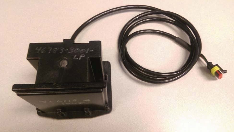
B7JDJCRVSIII
Oct 26, 2015Radar Velocity Sensor
Equipment Class
FDS - Part 15 Field Disturbance SensorB7J8LRDJRVSII
Nov 19, 1984FDS - Part 15 Field Disturbance Sensor
Equipment Class
FDS - Part 15 Field Disturbance SensorB7J8LRDJRVS1
Mar 24, 1982000 - No Equipment Class Selected
Equipment Class
000 - No Equipment Class Selected