BCGA1143802.11 a/b/g/n Access Point
Apple Inc.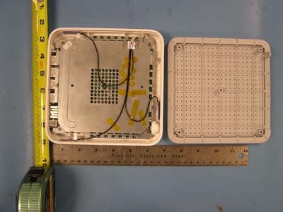
Click to zoom
Application Details
- Equipment Class
- NII - Unlicensed National Information Infrastructure TX
- Date of Grant
- Jan 08, 2007
- Application Purpose
- Original Equipment
- Date of Application
- Jan 08, 2007
- Equipment Note
- 802.11 a/b/g/n Access Point
- Frequency Range
- 5190.00000000 - 5230.00000000
- Company
- Apple Inc.
- Country
- United States
Documents & Files
Document Text
Text extracted from the exhibit documents filed with the FCC. Open a document above to read the original.
Users Manual
AirPort Extreme Setup Guide 2 Contents 3Chapter 1: Getting Started 11Chapter 2: AirPort Extreme Networks 12 Using AirPort Extreme with Your Broadband Internet Service 14 Using AirPort Extreme to Share a USB Printer 16 Using AirPort Extreme to Share a USB Hard Disk 18 Using AirPort Extreme with Your AirPort Network 20Chapter 3: Setting Up AirPort Extreme 25Chapter 4: Tips and Troubleshooting 33Chapter 5: Learning More, Service, and Support 1 3 1 Getting Started Congratulations on purchasing AirPort Extreme. Read this guide to get started using it. AirPort Extreme is based on the Institute of Electrical and Electronics Engineers (IEEE) draft 802.11n standard, the fastest wireless standard, which provides better performance and greater range than previous IEEE 802.11 standards. AirPort Extreme is compatible with computers using 802.11b and 802.11g, as well as computers using the 802.11a wireless standards. With AirPort Extreme, you can:  Create a wireless network in your home, and then connect to the Internet and share the connection with multiple computers simultaneously. An entire family or office can be connected to the Internet at the same time.  Connect AirPort Extreme to your Ethernet network. Wireless-equipped Macintosh computers or Windows XP computers can access an entire network without being connected by a cable.  Connect a USB printer to your AirPort Extreme. All of the compatible computers on the AirPort network, both wireless and wired, can print to it. 4Chapter 1 Getting Started  Connect a USB hard disk to your AirPort Extreme. All of the compatible computers on the AirPort network, both wireless and wired, can access the information on the hard disk.  Connect a USB hub to your AirPort Extreme, and then connect multiple USB devices, such as printers or hard disks. All of the computers on the network can access those devices. Chapter 1 Getting Started 5 About AirPort Extreme AirPort Extreme has five ports, located on the back side:  One Ethernet Wide Area Network (WAN) port (< ) for connecting a DSL or cable modem, or for connecting to an existing Ethernet network  Three 10/100 Ethernet Local Area Network (LAN) ports (G ) for connecting Ethernet devices, such as printers or computers, or for connecting to an existing Ethernet network  One USB port (d ) for connecting a compatible USB printer, hard disk, or hub Next to the ports is a reset button, which is used for troubleshooting your AirPort Extreme. The status light on the front of AirPort Extreme shows the current status. Status lightInternet WAN port AC adapter Power portUSB port Ethernet portsReset button Security slot 6Chapter 1 Getting Started About the AirPort Software AirPort Extreme works with the AirPort software included on the AirPort Extreme CD. AirPort Utility AirPort Utility helps you set up your AirPort Extreme to create a wireless network, connect to the Internet, and share a USB printer or hard disk. You can also connect your AirPort Extreme to your existing AirPort Extreme or AirPort Extreme wireless network to extend the range of your network using a Wireless Distribution System (WDS). Use the setup assistant in AirPort Utility to quickly and easily set up your AirPort Extreme and your wireless network. AirPort Utility is also an advanced tool for setting up and managing AirPort Extreme and AirPort Express Base Stations. Use AirPort Utility to adjust network, routing, and security settings and other advanced options. Z AirPort status menu in the menu bar Use the AirPort status menu to switch quickly between AirPort networks, monitor the signal quality of the current network, create a computer-to-computer network, and turn AirPort on and off. The status menu is available on computers using Mac OS X. Chapter 1 Getting Started 7 What You Need to Get Started To set up AirPort Extreme using a Macintosh, you must have the following:  A Macintosh computer with an AirPort or AirPort Extreme Card installed to set it up wirelessly  A Macintosh computer connected to AirPort Extreme with an Ethernet cable to set it up using Ethernet  Mac OS X v10.4 or later  AirPort Utility 5 or later To set up AirPort Extreme using a Windows PC, you must have the following:  A Windows PC with 300-MHz or higher processor speed  Windows XP Home or Professional (with Service Pack 2 installed)  AirPort Utility 5 or later You can use AirPort Extreme with any wireless-enabled computer that is compliant with the IEEE 802.11a, 802.11b, 802.11g standards, or with draft 802.11n. To set up AirPort Extreme, your computer must meet the requirements listed above. Install the AirPort software that came on the CD and follow the instructions on the following pages to set up your AirPort Extreme and your AirPort wireless network. Plugging In AirPort Extreme Before you plug in your AirPort Extreme, first connect the appropriate cables to the ports you want to use, including:  An Ethernet cable connected to your DSL or cable modem (if you will connect to the Internet) to the Ethernet (WAN) port (< ) 8Chapter 1 Getting Started  A USB cable to the USB port (d ) and to a compatible USB printer (if you will print to a USB printer), a USB hard disk, or USB hub  Any Ethernet devices to the Ethernet LAN (G ) ports After you have connected the cables for all the devices you plan to use, connect the AC plug adapter, and plug AirPort Extreme into the wall. There is no “on” switch. Important: Use only the AC adapter that came with your AirPort Extreme. When you plug AirPort Extreme into the wall, the status light flashes green for one second, and then glows amber while it starts up. After it has started up completely, the status light glows solid green. Power portEthernet activity light AC adapter Chapter 1 Getting Started 9 When you connect Ethernet cables to the Ethernet LAN (G ) ports, the lights above the ports blink when there is network activity. AirPort Extreme Status Lights The following table explains AirPort Extreme light sequences and …
Text truncated - open the document above for the full version.
Cover Letter(s)
Question#2. Please submit a detailed description of the 3x3 MIMO operation (i.e. is this a Spatial Multiplexed device, does it have cyclic diversity, are the antenna elements driven incoherently, etc.). Is this transmitter capable of operating on multiple channels simultaneously? Answer: This device uses Spatial Multiplexing. It employees a 2-stream 3x3 configuration. It includes three transmitters and three receivers with two incoherent streams. This devices also employs Cyclic Delay Diversity to improve range and throughput. In HT40 mode, this devices simultaneously operates on two adjacent channels.
Cover Letter(s)
1 Chris Harvey From: Claire Hoque [[email protected]] Sent: Tuesday, December 05, 2006 7:06 PM To: Chris Harvey Cc: Michael Heckrotte; Chi Tsou; Christine Vu Subject: answer: APPLE COMPUTER, FCC ID: BCGA1143, Assessment NO.: AN06T6237 - UNII, Notice#1 Attachments: Manual(revised).pdf; Additional Internal Photos.pdf; BCGA1143 Label.pdf; BCGA1143 MIMO details.pdf Manual(revised).pd f (736 KB) Additional Internal Photos.pdf... BCGA1143 Label.pdf (85 KB) BCGA1143 MIMO details.pdf (36 ... Hi Chris, Pls see answer below. Pls note the defer date is Jan. 9, 2007. Thanks, Claire -----Original Message----- From: Chris Harvey Sent: Sunday, November 26, 2006 7:04 PM To: Michael Heckrotte Cc: Chris Harvey; Claire Hoque Subject: APPLE COMPUTER, FCC ID: BCGA1143, Assessment NO.: AN06T6237 - UNII, Notice#1 Dear Michael Heckrotte, You are listed as the technical contact for the above referenced TCB application. The following items need to be addressed before the review can be completed: Please submit internal photographs with a resolution sufficient to resolve components on the board. <answer>attached pls find additional internal photos. 1. Please provide label photo/drawing and label location exhibits. <answer>attached pls find reivsed FCC Label. 2. Please submit a detailed description of the 3x3 MIMO operation (i.e. is this a Spatial Multiplexed device, does it have cyclic diversity, are the antenna elements driven incoherently, etc.). Is this transmitter capable of operating on multiple channels simultaneously? <answer>attached. 3. Please provide updated information in the Users Manual which informs the users about RF Exposure and the requirement to provide at least a 20cm separation to comply with FCC 15.247 and 15.407. <answer>attached pls find revised manual. 4. Please provide a description of the products compliance with the requirements of FCC 15.407(c). <answer> FCC 15.407(e) states: "The device shall automatically discontinue transmission in case of either absence of information to transmit or operational failure." Data transmission is always initiated by software, which is then passed through the MAC, through the digital and analog baseband, and finally to the RF chip. Several special packets (ACKs, CTS, 2 PSPoll, etc...) are initiated by the MAC. These are the only ways by which the digital baseband portion will turn on the RF transmitter, which it then turns off at the end of the packet. Therefore, the transmitter will be on only while one of the aforementioned packets is being transmitted. 5. There is a simple statement in the manual regarding use indoors, but no mention about the need to operate indoors in order to comply with the FCC 15.407 requirements for the 5.15-5.25GHz band. Please update the users manual about the need to use this device indoors during operation in the 5.15-5.25GHz band in order to comply with FCC 15.407. <answer>attached pls find revised manual. Please note that the associated application for the DTS portion (Assessment # AN06T6236) is being addressed separately. The items indicated above must be submitted before processing can continue on the above referenced application. Failure to provide the requested information within 30 days of the original e-mail date may result in application dismissal and forfeiture of the filing fee. Also, please note that partial responses increase processing time and should not be submitted. Any questions about the content of this correspondence should be directed to the e-mail address listed below the name of the sender. Best regards, Chris Harvey [email protected]
ID Label/Location Info
Label goes here
RF Exposure Info
REPORT NO: 06U10333-2 DATE: SEPTEMBER 29, 2006 EUT: 802.11 a/b/g/n ACCESS POINT FCC ID: BCGA1143 Page 174 of 219 COMPLIANCE CERTIFICATION SERVICES DOCUMENT NO: CCSUP4031A 561F MONTEREY ROAD, MORGAN HILL, CA 95037 USA TEL: (408) 463-0885 FAX: (408) 463-0888 This report shall not be reproduced except in full, without the written approval of CCS. 7.1.6. MAXIMUM PERMISSIBLE EXPOSURE LIMITS §1.1310 The criteria listed in Table 1 shall be used to evaluate the environmental impact of human exposure to radio-frequency (RF) radiation as specified in §1.1307(b), except in the case of portable devices which shall be evaluated according to the provisions of §2.1093 of this chapter. REPORT NO: 06U10333-2 DATE: SEPTEMBER 29, 2006 EUT: 802.11 a/b/g/n ACCESS POINT FCC ID: BCGA1143 Page 175 of 219 COMPLIANCE CERTIFICATION SERVICES DOCUMENT NO: CCSUP4031A 561F MONTEREY ROAD, MORGAN HILL, CA 95037 USA TEL: (408) 463-0885 FAX: (408) 463-0888 This report shall not be reproduced except in full, without the written approval of CCS. CALCULATIONS Given E = √ (30 * P * G) / d and S = E ^ 2 / 3770 where E = Field Strength in Volts/meter P = Power in Watts G = Numeric antenna gain d = Distance in meters S = Power Density in milliwatts/square centimeter Combining equations yields: S = (30 * P * G) / (3770 * (d ^ 2)) Changing to units of Power to mW and Distance to cm, using: P (W) = P (mW) / 1000 and d (m) = d (cm) / 100 and substituting the logarithmic form of power and gain using: P (mW) = 10 ^ (P (dBm) / 10) and G (numeric) = 10 ^ (G (dBi) / 10) yields S = 0.0795 * 10 ^ ((P + G) / 10) / (d^2) where d = MPE distance in cm P = Power in dBm G = Antenna Gain in dBi S = Power Density Limit in mW/cm^2 REPORT NO: 06U10333-2 DATE: SEPTEMBER 29, 2006 EUT: 802.11 a/b/g/n ACCESS POINT FCC ID: BCGA1143 Page 176 of 219 COMPLIANCE CERTIFICATION SERVICES DOCUMENT NO: CCSUP4031A 561F MONTEREY ROAD, MORGAN HILL, CA 95037 USA TEL: (408) 463-0885 FAX: (408) 463-0888 This report shall not be reproduced except in full, without the written approval of CCS. LIMITS From §1.1310 Table 1 (B), the maximum value of S = 1.0 mW/cm^2 RESULTS No non-compliance noted: NOTE: For mobile or fixed location transmitters, the minimum separation distance is 20 cm, even if calculations indicate that the MPE distance would be less. BandPower DensityTotalAntennaMPE LimitPowerGainDistance (MHz)(mW/cm^2)(dBm)(dBi)(cm) 5150 to 52501.016.943.002.80
RF Exposure Info
REPORT NO: 06U10333-2B DATE: MARCH 2, 2007 EUT: 802.11 a/b/g/n ACCESS POINT FCC ID: BCGA1143 Page 174 of 219 COMPLIANCE CERTIFICATION SERVICES DOCUMENT NO: CCSUP4031A 561F MONTEREY ROAD, MORGAN HILL, CA 95037 USA TEL: (408) 463-0885 FAX: (408) 463-0888 This report shall not be reproduced except in full, without the written approval of CCS. 7.1.6. MAXIMUM PERMISSIBLE EXPOSURE LIMITS §1.1310 The criteria listed in Table 1 shall be used to evaluate the environmental impact of human exposure to radio-frequency (RF) radiation as specified in §1.1307(b), except in the case of portable devices which shall be evaluated according to the provisions of §2.1093 of this chapter. REPORT NO: 06U10333-2B DATE: MARCH 2, 2007 EUT: 802.11 a/b/g/n ACCESS POINT FCC ID: BCGA1143 Page 175 of 219 COMPLIANCE CERTIFICATION SERVICES DOCUMENT NO: CCSUP4031A 561F MONTEREY ROAD, MORGAN HILL, CA 95037 USA TEL: (408) 463-0885 FAX: (408) 463-0888 This report shall not be reproduced except in full, without the written approval of CCS. CALCULATIONS Given E = √ (30 * P * G) / d and S = E ^ 2 / 3770 where E = Field Strength in Volts/meter P = Power in Watts G = Numeric antenna gain d = Distance in meters S = Power Density in milliwatts/square centimeter Combining equations yields: S = (30 * P * G) / (3770 * (d ^ 2)) Changing to units of Power to mW and Distance to cm, using: P (W) = P (mW) / 1000 and d (m) = d (cm) / 100 and substituting the logarithmic form of power and gain using: P (mW) = 10 ^ (P (dBm) / 10) and G (numeric) = 10 ^ (G (dBi) / 10) yields S = 0.0795 * 10 ^ ((P + G) / 10) / (d^2) where d = MPE distance in cm P = Power in dBm G = Antenna Gain in dBi S = Power Density Limit in mW/cm^2 REPORT NO: 06U10333-2B DATE: MARCH 2, 2007 EUT: 802.11 a/b/g/n ACCESS POINT FCC ID: BCGA1143 Page 176 of 219 COMPLIANCE CERTIFICATION SERVICES DOCUMENT NO: CCSUP4031A 561F MONTEREY ROAD, MORGAN HILL, CA 95037 USA TEL: (408) 463-0885 FAX: (408) 463-0888 This report shall not be reproduced except in full, without the written approval of CCS. LIMITS From §1.1310 Table 1 (B), the maximum value of S = 1.0 mW/cm^2 RESULTS No non-compliance noted: ModeMPETotal AntennaPower DistancePowerGainDensity (cm)(dBm)(dBi)(mW/cm^2) 20.016.947.770.06 Note: Effective Legacy Antenna Gain is used 802.11a
Test Report
FCC CFR47 PART 15 SUBPART E CERTIFICATION TEST REPORT FOR 802.11 a/b/g/n ACCESS POINT MODEL NUMBER: A1143 FCC ID: BCGA1143 REPORT NUMBER: 06U10333-2 ISSUE DATE: SEPTEMBER 29, 2006 Prepared for APPLE COMPUTER, INC. 1 INFINITE LOOP, M/S 26A CUPERTINO, CA 95014, USA Prepared by COMPLIANCE CERTIFICATION SERVICES 561F MONTEREY ROAD MORGAN HILL, CA 95037, USA TEL: (408) 463-0885 FAX: (408) 463-0888 REPORT NO: 06U10333-2 DATE: SEPTEMBER 29, 2006 EUT: 802.11 a/b/g/n ACCESS POINT FCC ID: BCGA1143 Page 2 of 219 COMPLIANCE CERTIFICATION SERVICES DOCUMENT NO: CCSUP4031A 561F MONTEREY ROAD, MORGAN HILL, CA 95037 USA TEL: (408) 463-0885 FAX: (408) 463-0888 This report shall not be reproduced except in full, without the written approval of CCS. Revision History Rev. Issue Date Revisions Revised By -- 9/29/2006 Initial Release A. Ilarina REPORT NO: 06U10333-2 DATE: SEPTEMBER 29, 2006 EUT: 802.11 a/b/g/n ACCESS POINT FCC ID: BCGA1143 Page 3 of 219 COMPLIANCE CERTIFICATION SERVICES DOCUMENT NO: CCSUP4031A 561F MONTEREY ROAD, MORGAN HILL, CA 95037 USA TEL: (408) 463-0885 FAX: (408) 463-0888 This report shall not be reproduced except in full, without the written approval of CCS. TABLE OF CONTENTS 1. ATTESTATION OF TEST RESULTS............................................................................................. 4 2. TEST METHODOLOGY .................................................................................................................. 5 3. FACILITIES AND ACCREDITATION .......................................................................................... 5 4. CALIBRATION AND UNCERTAINTY.......................................................................................... 5 4.1. MEASURING INSTRUMENT CALIBRATION ............................................................................. 5 4.2. MEASUREMENT UNCERTAINTY ............................................................................................... 5 5. EQUIPMENT UNDER TEST............................................................................................................6 5.1. DESCRIPTION OF EUT ..............................................................................................................6 5.2. MAXIMUM OUTPUT POWER .................................................................................................... 6 5.3. DESCRIPTION OF AVAILABLE ANTENNAS ............................................................................. 7 5.4. SOFTWARE AND FIRMWARE .................................................................................................... 7 5.5. WORST-CASE CONFIGURATION AND MODE......................................................................... 7 5.6. MODIFICATIONS ........................................................................................................................ 7 5.7. DESCRIPTION OF TEST SETUP ................................................................................................ 8 6. TEST AND MEASUREMENT EQUIPMENT .............................................................................. 10 7. LIMITS AND RESULTS ................................................................................................................. 11 7.1. CHANNEL TESTS FOR THE 5150 TO 5250 MHz BAND ......................................................... 11 7.1.1. 99% BANDWIDTH AND 26 dB BANDWIDTH .............................................................. 11 7.1.2. MAXIMUM POWER ......................................................................................................... 40 7.1.3. PEAK POWER SPECTRAL DENSITY ............................................................................ 69 7.1.4. PEAK EXCURSION ........................................................................................................ 108 7.1.5. CONDUCTED SPURIOUS EMISSIONS........................................................................ 137 7.1.6. MAXIMUM PERMISSIBLE EXPOSURE ...................................................................... 174 7.2. RADIATED EMISSIONS........................................................................................................... 177 7.2.1. TRANSMITTER RADIATED SPURIOUS EMISSIONS ............................................... 177 7.2.2. TRANSMITTER ABOVE 1 GHz FOR 5150 TO 5250 MHz BAND .............................. 179 7.2.3. WORST-CASE RADIATED EMISSIONS BELOW 1 GHz ........................................... 206 7.3. FREQUENCY STABILITY ........................................................................................................ 208 7.4. POWERLINE CONDUCTED EMISSIONS .............................................................................. 210 8. SETUP PHOTOS ............................................................................................................................ 214 REPORT NO: 06U10333-2 DATE: SEPTEMBER 29, 2006 EUT: 802.11 a/b/g/n ACCESS POINT FCC ID: BCGA1143 Page 4 of 219 COMPLIANCE CERTIFICATION SERVICES DOCUMENT NO: CCSUP4031A 561F MONTEREY ROAD, MORGAN HILL, CA 95037 USA TEL: (408) 463-0885 FAX: (408) 463-0888 This report shall not be reproduced except in full, without the written approval of CCS. 1. ATTESTATION OF TEST RESULTS COMPANY NAME: APPLE COMPUTER, INC. 1 INFINITE LOOP, M/S 26A CUPERTINO, CA 95014 U.S.A. EUT DESCRIPTION: 802.11 a/b/g/n ACCESS POINT MODEL: A1143 SERIAL NUMBER: 6F619000KVYBE 6F6270010VV6E 6F61801FVZC DATE TESTED: AUGUST 1-24, 2006 APPLICABLE STANDARDS STANDARD TEST RESULTS FCC PART 15 SUBPART C NO NON-COMPLIANCE NOTED Compliance Certification Services, Inc. tested the above equipment in accordance with the requirements set forth in the above standards. The test results show that the equipment tested is capable of demonstrating compliance with the requirements as documented in this report. Note: The results documented in this report apply only to the tested sample, under the conditions and modes of operation as described herein. This docume…
Text truncated - open the document above for the full version.
Test Setup Photos
REPORT NO: 06U10333-2 DATE: SEPTEMBER 29, 2006 EUT: 802.11 a/b/g/n ACCESS POINT FCC ID: BCGA1143 Page 214 of 219 COMPLIANCE CERTIFICATION SERVICES DOCUMENT NO: CCSUP4031A 561F MONTEREY ROAD, MORGAN HILL, CA 95037 USA TEL: (408) 463-0885 FAX: (408) 463-0888 This report shall not be reproduced except in full, without the written approval of CCS. 8. SETUP PHOTOS ANTENNA PORT CONDUCTED RF MEASUREMENT SETUP ANTENNA PORT CONDUCTED PHOTO REPORT NO: 06U10333-2 DATE: SEPTEMBER 29, 2006 EUT: 802.11 a/b/g/n ACCESS POINT FCC ID: BCGA1143 Page 215 of 219 COMPLIANCE CERTIFICATION SERVICES DOCUMENT NO: CCSUP4031A 561F MONTEREY ROAD, MORGAN HILL, CA 95037 USA TEL: (408) 463-0885 FAX: (408) 463-0888 This report shall not be reproduced except in full, without the written approval of CCS. RADIATED RF MEASUREMENT SETUP RADIATED FRONT PHOTO REPORT NO: 06U10333-2 DATE: SEPTEMBER 29, 2006 EUT: 802.11 a/b/g/n ACCESS POINT FCC ID: BCGA1143 Page 216 of 219 COMPLIANCE CERTIFICATION SERVICES DOCUMENT NO: CCSUP4031A 561F MONTEREY ROAD, MORGAN HILL, CA 95037 USA TEL: (408) 463-0885 FAX: (408) 463-0888 This report shall not be reproduced except in full, without the written approval of CCS. RADIATED BACK PHOTO REPORT NO: 06U10333-2 DATE: SEPTEMBER 29, 2006 EUT: 802.11 a/b/g/n ACCESS POINT FCC ID: BCGA1143 Page 217 of 219 COMPLIANCE CERTIFICATION SERVICES DOCUMENT NO: CCSUP4031A 561F MONTEREY ROAD, MORGAN HILL, CA 95037 USA TEL: (408) 463-0885 FAX: (408) 463-0888 This report shall not be reproduced except in full, without the written approval of CCS. POWERLINE CONDUCTED EMISSIONS MEASUREMENT SETUP LINE CONDUCTED FRONT PHOTO REPORT NO: 06U10333-2 DATE: SEPTEMBER 29, 2006 EUT: 802.11 a/b/g/n ACCESS POINT FCC ID: BCGA1143 Page 218 of 219 COMPLIANCE CERTIFICATION SERVICES DOCUMENT NO: CCSUP4031A 561F MONTEREY ROAD, MORGAN HILL, CA 95037 USA TEL: (408) 463-0885 FAX: (408) 463-0888 This report shall not be reproduced except in full, without the written approval of CCS. LINE CONDUCTED BACK PHOTO REPORT NO: 06U10333-2 DATE: SEPTEMBER 29, 2006 EUT: 802.11 a/b/g/n ACCESS POINT FCC ID: BCGA1143 Page 219 of 219 COMPLIANCE CERTIFICATION SERVICES DOCUMENT NO: CCSUP4031A 561F MONTEREY ROAD, MORGAN HILL, CA 95037 USA TEL: (408) 463-0885 FAX: (408) 463-0888 This report shall not be reproduced except in full, without the written approval of CCS. END OF REPORT FREQUENCY STABILITY
Contact Information
Applicant
Abhishek Rala(Regulatory Compliance Manager)
Test Firm
Compliance Certification ServicesBarbara Judge
Technical Specifications
| # | Rule Parts | Frequency Range | Power Output |
|---|---|---|---|
| 3 | 15E | 5.19 GHz - 5.23 GHz | 49.43 mW |
Other Applications from Apple Inc.
BCG-E9204A
Sep 09, 2026Smartphone
Equipment Class
6VL - 15E 6 GHZ Very Low Power DeviceBCGA3277
Sep 09, 2026Magnetic Charging Cable
Equipment Class
DCD - Part 15 Low Power Transmitter Below 1705 kHzBCGA3641
Sep 09, 2026Magnetic Charger
Equipment Class
DCD - Part 15 Low Power Transmitter Below 1705 kHzBCGA3669
Sep 09, 2026Magnetic Charger
Equipment Class
DCD - Part 15 Low Power Transmitter Below 1705 kHzBCG-E9193A
Sep 09, 2026Smartphone
Equipment Class
PCE - PCS Licensed Transmitter held to ear