BCGA12642X2 Access Point
Apple Inc.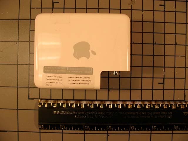
Click to zoom
Application Details
- Equipment Class
- NII - Unlicensed National Information Infrastructure TX
- Date of Grant
- Mar 11, 2008
- Application Purpose
- Original Equipment
- Date of Application
- Feb 24, 2008
- Equipment Note
- 2X2 Access Point
- Frequency Range
- 5190.00000000 - 5230.00000000
- Company
- Apple Inc.
- Country
- United States
Documents & Files
Document Text
Text extracted from the exhibit documents filed with the FCC. Open a document above to read the original.
Users Manual
AirPort Express Setup Guide 3 Contents 5Chapter 1: Getting Started 6 About AirPort Express 8 About the AirPort Software 8 What You Need to Get Started 10 Plugging In AirPort Express 11 AirPort Express Status Lights 12 What’s Next 13Chapter 2: Using AirPort Express 13 Using AirPort Express with Your Broadband Internet Service 15 Using AirPort Express on an Existing Wireless Network to Stream Music to Your Home Stereo 16 Using AirPort Express to Share a USB Printer 21Chapter 3: Setting Up AirPort Express 23 Using the AirPort Utility 25 Creating a New Wireless Network 25 Configuring and Sharing Internet Access 26 Connecting to an Existing Wireless Network 26 Allowing Wireless Clients Access to Your Network 4 Contents 28 Setting Advanced Options 31Chapter 4: Tips and Troubleshooting 37 AirPort Express Placement Considerations 38 Items That Can Cause Interference with AirPort 39Chapter 5: Learning More, Service, and Support 39 Online Resources 39 Onscreen Help 40 Obtaining Warranty Service 40 Finding the Serial Number of Your AirPort Express 41Appendix: AirPort Express Specifications 42 AirPort Express Safety Tips 43 Avoid Wet Locations 43 Do Not Make Repairs Yourself 45 Regulatory Compliance Information 1 5 1 Getting Started Congratulations on purchasing AirPort Express. Read this guide to get started using it. AirPort Express is based on an Institute of Electrical and Electronics Engineers (IEEE) draft 802.11n specification and provides better performance and greater range than previous IEEE 802.11 standards. AirPort Express is compatible with computers using 802.11b, and 802.11g, as well as computers using the 802.11a and 802.11n wireless standards. You can use AirPort Express to share your broadband Internet access with wireless computers on your network, play iTunes music on your home stereo, and share a USB printer. Your AirPort Express comes with AirTunes, a way to play iTunes music through remote speakers. With AirPort Express, you can:  Create a wireless network in your home, and then connect to the Internet and share the connection with up to ten computers simultaneously. An entire family can be connected to the Internet at the same time. 6Chapter 1 Getting Started  Connect AirPort Express to your home stereo or powered speakers and use AirTunes to play your iTunes music on your home stereo from a Macintosh with an AirPort or AirPort Extreme Card, or a compatible Windows XP or Windows 2000 wireless computer.  Set up a wireless connection to your Ethernet network. AirPort and AirPort Extreme- equipped Macintosh computers or Windows Vista or Windows XP computers can then have access to an entire network without being connected with a cable.  Connect a USB printer to your AirPort Express. All of the compatible computers on the AirPort network, both wireless and wired, can print to it. About AirPort Express AirPort Express has three ports, located on the bottom side:  Ethernet port (G ) for connecting a DSL or cable modem, or for connecting to an existing Ethernet network  Analog and optical digital audio stereo mini-jack (- ) for connecting AirPort Express to a home stereo or powered speakers Chapter 1 Getting Started 7  USB port (d ) for connecting a compatible printer to AirPort Express Next to the ports is a reset button, which is used for troubleshooting your AirPort Express. The status light on the side of AirPort Express shows the current status. Status light Reset button Line Out port (Analog and optical digital audio mini-jack) Ethernet port USB port AC plug adapter 8Chapter 1 Getting Started About the AirPort Software AirPort Express works with the AirPort software included on the AirPort Express CD. What You Need to Get Started To set up AirPort Express using a Macintosh, you must have the following:  A Macintosh computer with an AirPort or AirPort Extreme Card installed  Mac OS X v10.4 or later AirPort Utility AirPort Utility helps you set up your AirPort Express to create a wireless network, connect to the Internet, and share a USB printer. You can also connect your AirPort Express to your existing AirPort Express or AirPort Extreme wireless network to extend the range of your network using WDS. Use AirPort Utility to quickly and easily set up your AirPort Express and your wireless network. AirPort Utility is also an advanced tool for setting up and managing AirPort Extreme and AirPort Express Base Stations. Use AirPort Utility to adjust network, routing, and security settings and other advanced options. AirPort status menu in the menu bar Use the AirPort status menu to switch quickly between AirPort networks, monitor the signal quality of the current network, create a Computer-to-Computer network, and turn AirPort on and off. The status menu is available on computers using Mac OS X. Z Chapter 1 Getting Started 9 To set up AirPort Express using a Windows PC, you must have the following:  A Windows PC with 300 MHz or higher processor speed with a compatible 802.11a, 802.11b, 802.11g, or 802.11n wireless adapter  Windows Vista or Windows XP with service pack 2 You need iTunes to play audio from your computer to a stereo connected to AirPort Express. To be sure you have the latest version of iTunes, go to www.apple.com/itunes. You can use AirPort Express with any wireless-enabled computer that is compliant with the IEEE 802.11a, 802.11b, 802.11g, or 802.11n standards. To set up AirPort Express, your computer must meet the requirements listed above. 10Chapter 1 Getting Started Plugging In AirPort Express Before you plug in your AirPort Express, first connect the appropriate cables to the ports you want to use, including the Ethernet cable connected to your DSL or cable modem (if you will connect to the Internet), the audio cable connected to your stereo (if you will use AirTunes to play music from iTunes), and a USB cable connected to a compatible USB printer (if you will print to a USB printer). After you have connected the cables for all the devices you plan to use…
Text truncated - open the document above for the full version.
ID Label/Location Info
A1264 Label A1264 Label Location
RF Exposure Info
REPORT NO: 07U11408-2A DATE: FEBRUARY 14, 2008 FCC ID: BCGA1264 IC: 579C-A1264 Page 186 of 198 COMPLIANCE CERTIFICATION SERVICES FORM NO: CCSUP4031B 47173 BENICIA STREET, FREMONT, CA 94538, USA TEL: (510) 771-1000 FAX: (510) 661-0888 This report shall not be reproduced except in full, without the written approval of CCS. 10. MAXIMUM PERMISSIBLE EXPOSURE FCC RULES §1.1310 The criteria listed in Table 1 shall be used to evaluate the environmental impact of human exposure to radio-frequency (RF) radiation as specified in §1.1307(b), except in the case of portable devices which shall be evaluated according to the provisions of §2.1093 of this chapter. REPORT NO: 07U11408-2A DATE: FEBRUARY 14, 2008 FCC ID: BCGA1264 IC: 579C-A1264 Page 187 of 198 COMPLIANCE CERTIFICATION SERVICES FORM NO: CCSUP4031B 47173 BENICIA STREET, FREMONT, CA 94538, USA TEL: (510) 771-1000 FAX: (510) 661-0888 This report shall not be reproduced except in full, without the written approval of CCS. IC RULES IC Safety Code 6, Section 2.2.1 (a) A person other than an RF and microwave exposed worker shall not be exposed to electromagnetic radiation in a frequency band listed in Column 1 of Table 5, if the field strength exceeds the value given in Column 2 or 3 of Table 5, when averaged spatially and over time, or if the power density exceeds the value given in Column 4 of Table 5, when averaged spatially and over time. REPORT NO: 07U11408-2A DATE: FEBRUARY 14, 2008 FCC ID: BCGA1264 IC: 579C-A1264 Page 188 of 198 COMPLIANCE CERTIFICATION SERVICES FORM NO: CCSUP4031B 47173 BENICIA STREET, FREMONT, CA 94538, USA TEL: (510) 771-1000 FAX: (510) 661-0888 This report shall not be reproduced except in full, without the written approval of CCS. CALCULATIONS Given E = √ (30 * P * G) / d and S = E ^ 2 / 3770 where E = Field Strength in Volts/meter P = Power in Watts G = Numeric antenna gain d = Distance in meters S = Power Density in milliwatts/square centimeter Combining equations, rearranging the terms to express the distance as a function of the remaining variables, changing to units of Power to mW and Distance to cm, and substituting the logarithmic form of power and gain yields: d = 0.282 * 10 ^ ((P + G) / 20) / √ S where d = MPE distance in cm P = Power in dBm G = Antenna Gain in dBi S = Power Density Limit in mW/cm^2 Rearranging terms to calculate the power density at a specific distance yields S = 0.0795 * 10 ^ ((P + G) / 10) / (d^2) The power density in units of mW/cm^2 is converted to units of W/m^2 by multiplying by a factor of 10. REPORT NO: 07U11408-2A DATE: FEBRUARY 14, 2008 FCC ID: BCGA1264 IC: 579C-A1264 Page 189 of 198 COMPLIANCE CERTIFICATION SERVICES FORM NO: CCSUP4031B 47173 BENICIA STREET, FREMONT, CA 94538, USA TEL: (510) 771-1000 FAX: (510) 661-0888 This report shall not be reproduced except in full, without the written approval of CCS. LIMITS From FCC §1.1310 Table 1 (B), the maximum value of S = 1.0 mW/cm^2 From IC Safety Code 6, Section 2.2 Table 5 Column 4, S = 10 W/m^2 RESULTS (MPE distance is equal to 20 cm) ModeBandMPEOutputAntennaFCC PowerIC Power DistancePowerGainDensityDensity (cm)(dBm)(dBi)(mW/cm^2)(W/m^2) 802.11a 5 GHz20.012.831.530.00540.0542 802.11n HT20 5 GHz20.013.571.530.00640.0643 802.11n HT40 5 GHz20.016.161.530.01170.1168
Test Report
FCC CFR47 PART 15 SUBPART E INDUSTRY CANADA RSS-210 ISSUE 7 CERTIFICATION TEST REPORT FOR 2X2 ACCESS POINT MODEL NUMBER: A1264 FCC ID: BCGA1264 IC: 579C-A1264 REPORT NUMBER: 07U11408-2, REVISION A ISSUE DATE: FEBRUARY 14, 2008 Prepared for APPLE, INC. 1 INFINITE LOOP CUPERTINO, CA 95014, USA Prepared by COMPLIANCE CERTIFICATION SERVICES 47173 BENICIA STREET FREMONT, CA 94538, U.S.A. TEL: (510) 771-1000 FAX: (510) 661-0888 REPORT NO: 07U11408-2A DATE: FEBRUARY 14, 2008 FCC ID: BCGA1264 IC: 579C-A1264 Page 2 of 198 COMPLIANCE CERTIFICATION SERVICES FORM NO: CCSUP4031B 47173 BENICIA STREET, FREMONT, CA 94538, USA TEL: (510) 771-1000 FAX: (510) 661-0888 This report shall not be reproduced except in full, without the written approval of CCS. Revision History Rev. Issue Date Revisions Revised By -- 01/18/08 Initial Issue F. Ibrahim A 02/14/08 Revised the MPE section. F. Ibrahim REPORT NO: 07U11408-2A DATE: FEBRUARY 14, 2008 FCC ID: BCGA1264 IC: 579C-A1264 Page 3 of 198 COMPLIANCE CERTIFICATION SERVICES FORM NO: CCSUP4031B 47173 BENICIA STREET, FREMONT, CA 94538, USA TEL: (510) 771-1000 FAX: (510) 661-0888 This report shall not be reproduced except in full, without the written approval of CCS. TABLE OF CONTENTS 1. ATTESTATION OF TEST RESULTS.................................................................................... 5 2. TEST METHODOLOGY ........................................................................................................ 6 3. FACILITIES AND ACCREDITATION.................................................................................... 6 4. CALIBRATION AND UNCERTAINTY .................................................................................. 6 4.1. MEASURING INSTRUMENT CALIBRATION ............................................................... 6 4.2. MEASUREMENT UNCERTAINTY................................................................................ 6 5. EQUIPMENT UNDER TEST ................................................................................................. 7 5.1. DESCRIPTION OF EUT................................................................................................ 7 5.2. MAXIMUM OUTPUT POWER....................................................................................... 7 5.3. DESCRIPTION OF AVAILABLE ANTENNAS............................................................... 8 5.4. SOFTWARE AND FIRMWARE..................................................................................... 9 5.5. WORST-CASE CONFIGURATION AND MODE .......................................................... 9 5.6. DESCRIPTION OF TEST SETUP............................................................................... 10 6. TEST AND MEASUREMENT EQUIPMENT ....................................................................... 12 7. ANTENNA PORT TEST RESULTS .................................................................................... 13 7.1. 802.11a DUAL CHAIN LEGACY MODE ..................................................................... 13 7.1.1. 26 dB and 99% BANDWIDTH ............................................................................. 13 7.1.2. OUTPUT POWER ............................................................................................... 26 7.1.3. PEAK POWER SPECTRAL DENSITY................................................................ 34 7.1.4. PEAK EXCURSION ............................................................................................ 45 7.1.5. CONDUCTED SPURIOUS EMISSIONS............................................................. 52 7.2. 802.11n HT20 MODE.................................................................................................. 62 7.2.1. 26 dB and 99% BANDWIDTH ............................................................................. 62 7.2.2. OUTPUT POWER ............................................................................................... 75 7.2.3. PEAK POWER SPECTRAL DENSITY................................................................ 83 7.2.4. PEAK EXCURSION ............................................................................................ 94 7.2.5. CONDUCTED SPURIOUS EMISSIONS........................................................... 101 7.3. 802.11n HT40 MODE................................................................................................ 111 7.3.1. 26 dB and 99% BANDWIDTH ........................................................................... 111 7.3.2. OUTPUT POWER ............................................................................................. 120 7.3.3. PEAK POWER SPECTRAL DENSITY.............................................................. 126 REPORT NO: 07U11408-2A DATE: FEBRUARY 14, 2008 FCC ID: BCGA1264 IC: 579C-A1264 Page 4 of 198 COMPLIANCE CERTIFICATION SERVICES FORM NO: CCSUP4031B 47173 BENICIA STREET, FREMONT, CA 94538, USA TEL: (510) 771-1000 FAX: (510) 661-0888 This report shall not be reproduced except in full, without the written approval of CCS. 7.3.4. PEAK EXCURSION .......................................................................................... 134 7.3.5. CONDUCTED SPURIOUS EMISSIONS........................................................... 139 8. RADIATED TEST RESULTS ............................................................................................ 146 8.1. LIMITS AND PROCEDURE ...................................................................................... 146 8.2. TRANSMITTER ABOVE 1 GHz ................................................................................ 148 8.2.1. TX ABOVE 1 GHz FOR 802.11a DUAL CHAIN LEGACY MODE..................... 148 8.2.2. TX ABOVE 1 GHz FOR 802.11n HT20 MODE ................................................. 157 8.2.3. TX ABOVE 1 GHz FOR 802.11n HT40 MODE ................................................. 166 8.3. RECEIVER ABOVE 1 GHz ....................................................................................…
Text truncated - open the document above for the full version.
Test Setup Photos
REPORT NO: 07U11408-2A DATE: FEBRUARY 14, 2008 FCC ID: BCGA1264 IC: 579C-A1264 Page 190 of 198 COMPLIANCE CERTIFICATION SERVICES FORM NO: CCSUP4031B 47173 BENICIA STREET, FREMONT, CA 94538, USA TEL: (510) 771-1000 FAX: (510) 661-0888 This report shall not be reproduced except in full, without the written approval of CCS. 11. SETUP PHOTOS ANTENNA PORT CONDUCTED RF MEASUREMENT SETUP ANTENNA PORT CONDUCTED PHOTO REPORT NO: 07U11408-2A DATE: FEBRUARY 14, 2008 FCC ID: BCGA1264 IC: 579C-A1264 Page 191 of 198 COMPLIANCE CERTIFICATION SERVICES FORM NO: CCSUP4031B 47173 BENICIA STREET, FREMONT, CA 94538, USA TEL: (510) 771-1000 FAX: (510) 661-0888 This report shall not be reproduced except in full, without the written approval of CCS. RADIATED RF MEASUREMENT SETUP FOR PORTABLE CONFIGURATION X-AXIS FRONT PHOTO REPORT NO: 07U11408-2A DATE: FEBRUARY 14, 2008 FCC ID: BCGA1264 IC: 579C-A1264 Page 192 of 198 COMPLIANCE CERTIFICATION SERVICES FORM NO: CCSUP4031B 47173 BENICIA STREET, FREMONT, CA 94538, USA TEL: (510) 771-1000 FAX: (510) 661-0888 This report shall not be reproduced except in full, without the written approval of CCS. X-AXIS BACK PHOTO REPORT NO: 07U11408-2A DATE: FEBRUARY 14, 2008 FCC ID: BCGA1264 IC: 579C-A1264 Page 193 of 198 COMPLIANCE CERTIFICATION SERVICES FORM NO: CCSUP4031B 47173 BENICIA STREET, FREMONT, CA 94538, USA TEL: (510) 771-1000 FAX: (510) 661-0888 This report shall not be reproduced except in full, without the written approval of CCS. Y-AXIS FRONT PHOTO REPORT NO: 07U11408-2A DATE: FEBRUARY 14, 2008 FCC ID: BCGA1264 IC: 579C-A1264 Page 194 of 198 COMPLIANCE CERTIFICATION SERVICES FORM NO: CCSUP4031B 47173 BENICIA STREET, FREMONT, CA 94538, USA TEL: (510) 771-1000 FAX: (510) 661-0888 This report shall not be reproduced except in full, without the written approval of CCS. Y-AXIS BACK PHOTO REPORT NO: 07U11408-2A DATE: FEBRUARY 14, 2008 FCC ID: BCGA1264 IC: 579C-A1264 Page 195 of 198 COMPLIANCE CERTIFICATION SERVICES FORM NO: CCSUP4031B 47173 BENICIA STREET, FREMONT, CA 94538, USA TEL: (510) 771-1000 FAX: (510) 661-0888 This report shall not be reproduced except in full, without the written approval of CCS. Z-AXIS FRONT PHOTO REPORT NO: 07U11408-2A DATE: FEBRUARY 14, 2008 FCC ID: BCGA1264 IC: 579C-A1264 Page 196 of 198 COMPLIANCE CERTIFICATION SERVICES FORM NO: CCSUP4031B 47173 BENICIA STREET, FREMONT, CA 94538, USA TEL: (510) 771-1000 FAX: (510) 661-0888 This report shall not be reproduced except in full, without the written approval of CCS. Z-AXIS BACK PHOTO REPORT NO: 07U11408-2A DATE: FEBRUARY 14, 2008 FCC ID: BCGA1264 IC: 579C-A1264 Page 197 of 198 COMPLIANCE CERTIFICATION SERVICES FORM NO: CCSUP4031B 47173 BENICIA STREET, FREMONT, CA 94538, USA TEL: (510) 771-1000 FAX: (510) 661-0888 This report shall not be reproduced except in full, without the written approval of CCS. POWERLINE CONDUCTED EMISSIONS MEASUREMENT SETUP LINE CONDUCTED FRONT PHOTO REPORT NO: 07U11408-2A DATE: FEBRUARY 14, 2008 FCC ID: BCGA1264 IC: 579C-A1264 Page 198 of 198 COMPLIANCE CERTIFICATION SERVICES FORM NO: CCSUP4031B 47173 BENICIA STREET, FREMONT, CA 94538, USA TEL: (510) 771-1000 FAX: (510) 661-0888 This report shall not be reproduced except in full, without the written approval of CCS. END OF REPORT LINE CONDUCTED BACK PHOTO
Contact Information
Applicant
Abhishek Rala(Regulatory Compliance Manager)
Test Firm
Compliance Certification ServicesBarbara Judge
Technical Specifications
| # | Rule Parts | Frequency Range | Power Output |
|---|---|---|---|
| 3 | 15E | 5.19 GHz - 5.23 GHz | 41.00 mW |
Other Applications from Apple Inc.
BCG-E9204A
Sep 09, 2026Smartphone
Equipment Class
6VL - 15E 6 GHZ Very Low Power DeviceBCGA3277
Sep 09, 2026Magnetic Charging Cable
Equipment Class
DCD - Part 15 Low Power Transmitter Below 1705 kHzBCGA3641
Sep 09, 2026Magnetic Charger
Equipment Class
DCD - Part 15 Low Power Transmitter Below 1705 kHzBCGA3669
Sep 09, 2026Magnetic Charger
Equipment Class
DCD - Part 15 Low Power Transmitter Below 1705 kHzBCG-E9193A
Sep 09, 2026Smartphone
Equipment Class
PCE - PCS Licensed Transmitter held to ear