BCGA14703X3 MIMO BASE STATION
Apple Inc.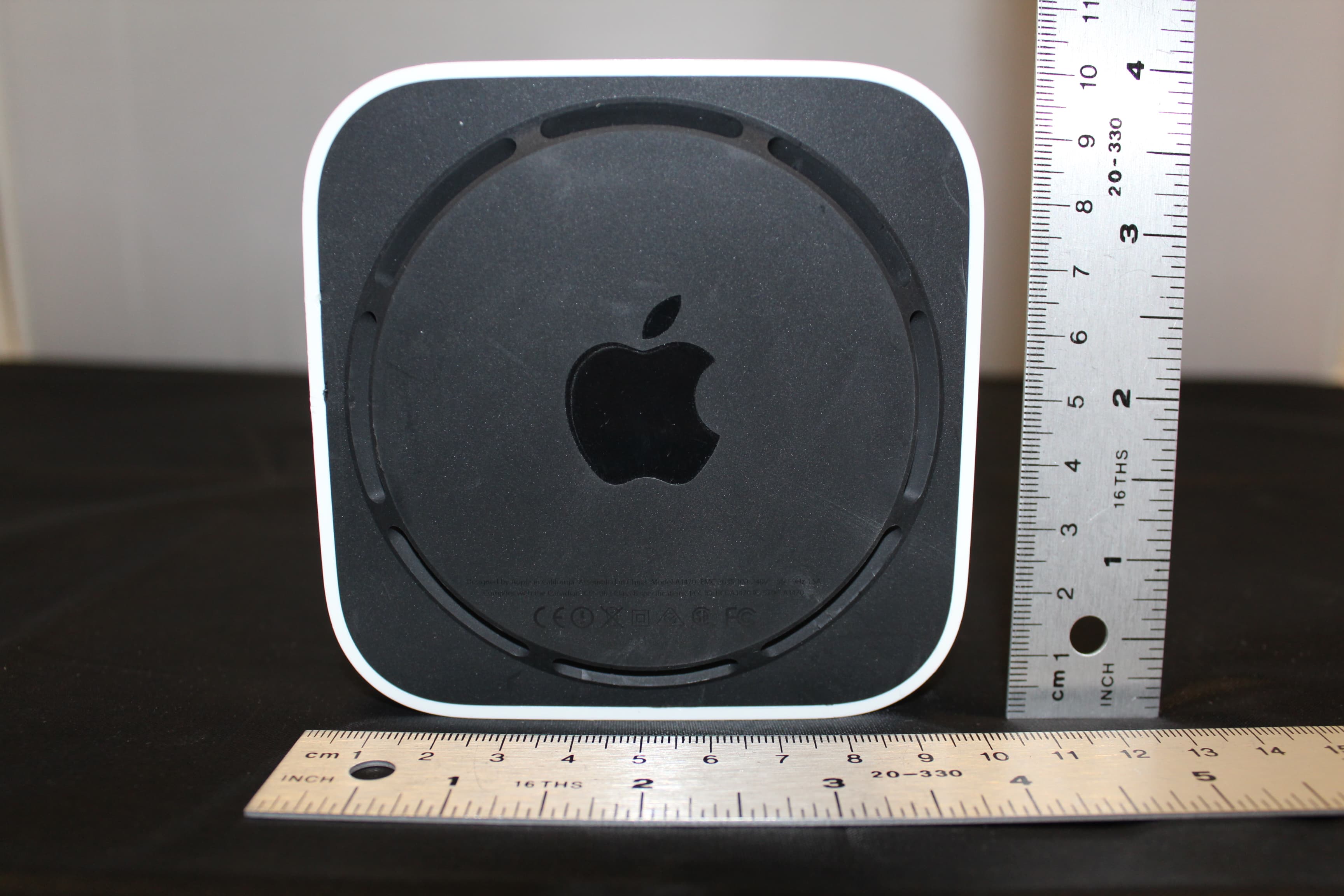
Click to zoom
Application Details
- Equipment Class
- DTS - Digital Transmission System
- Date of Grant
- Jun 09, 2013
- Application Purpose
- Original Equipment
- Date of Application
- Jun 06, 2013
- Equipment Note
- 3X3 MIMO BASE STATION
- Frequency Range
- 5745.00000000 - 5825.00000000
- Company
- Apple Inc.
- Country
- United States
Documents & Files
Document Text
Text extracted from the exhibit documents filed with the FCC. Open a document above to read the original.
Users Manual
Draft AirPort Time Capsule Setup Guide Apple Confidential Draft Apple Confidential Draft Contents 3 5 Getting Started 7 Ports on Your AirPort Time Capsule 8 Plugging In Your AirPort Time Capsule 9 The AirPor t Time Capsule Status Light 11 Setting Up Your AirPort Time Capsule 12 Setting Up AirPort Time Capsule Using a Mac 12 Setting Up AirPort Time Capsule Using an iOS device 13 Setting Adv anced Options 13 Using Time Machine with Your AirPort Time Capsule 14 Adding a WPS Printer to Your Password-Protected Network 16 Tips and Troubleshooting 16 Best Lo cations for AirPort Time Capsule 17 Avoiding Interference 17 If You C an’t Connect to the Internet 18 If You F orget Your AirPort Time Capsule or Network Password Apple Confidential Draft 4 19 If Your AirPort Time Capsule Isn’t Responding 19 If Your AirPort Time Capsule Status Light Flashes Amber 20 If You Want to Update Your AirPort Time Capsule Software 21 Learning M ore, Service, and Support 23 AirPort Time Capsule Specifications and Safety Guidelines Apple Confidential Draft 1 5 Congratulations on purchasing your AirPort Time Capsule. Read this guide to get started. AirPort Time Capsule offers you fully automated backup for computers on your Wi-Fi network. Using the Time Machine application in Mac OS X v10.5.7 or later, it’s easy and automatic to back up all the Mac computers on your network to a single AirPort Time Capsule. AirPort Time Capsule is also a fully featured AirPort Extreme Base Station that provides simultaneous dual-band wireless networking using the 802.11ac specification. When you set up your AirPort Time Capsule, it creates two high-speed Wi-Fi networks: ÂA 2.4 gigahertz (GHz) network for 802.11b, 802.11g, and 802.11n devices, such as iPhone, iPod touch, and older computers ÂA 5 GHz network for 802.11n, 802.11a, and 802.11ac devices, such as iPhone, iPad, Apple TV, and newer computers Wi-Fi devices automatically join the network that provides the best performance and compatibility, and AirPort Time Capsule shares your broadband Internet connection with computers and devices on your network. Getting Started Apple Confidential Draft Chapter 1 Getting Started6 Status light USB Ethernet LAN Power Ethernet WAN Link light Power cord (Your power cord may look different.) Reset button Apple Confidential Draft Chapter 1 Getting Started7 Ports on Your AirPort Time Capsule AirPort Time Capsule has six ports on the back: < One Gigabit Ethernet Wide Area Network (WAN) port For connecting a DSL or cable modem, or for connecting to an existing Ethernet network G Three Gigabit Ethernet Local Area Network (LAN) ports For connecting Ethernet devices such as printers or computers, or for connecting to an existing Ethernet network d One USB port For connecting a compatible USB printer, hard disk, or hub for connecting several devices ≤ Power port For connecting AirPort Time Capsule to an AC power source Next to the power port is a reset button for troubleshooting your AirPort Time Capsule. The status light on the front shows its current status. Apple Confidential Draft Chapter 1 Getting Started8 Plugging In Your AirPort Time Capsule Before you plug in your AirPort Time Capsule, first connect the appropriate cables to the ports you want to use: ÂConnect the Ethernet cable that’s connected to your DSL or cable modem (if you’ll connect to the Internet) to the Ethernet WAN port (<). ÂConnect a USB cable from the USB port (d) on your AirPort Time Capsule to a compatible USB printer, a hard disk, or a hub. ÂConnect an Ethernet cable from any Ethernet device to any of the Ethernet LAN ports (G). After you connect the cables for all the devices you plan to use, connect the power cord to the power port and plug your AirPort Time Capsule into a power outlet. There is no power switch. Important: Use only the power cord that came with your AirPort Time Capsule. When you plug the AirPort Time Capsule power cord into a power outlet, the status light glows amber during startup, and then flashes amber during setup. The status light glows green after your AirPort Time Capsule is set up and connected to the Internet or a network. When you connect Ethernet cables to the Ethernet ports, the lights above them glow solid green. Apple Confidential Draft Chapter 1 Getting Started9 The AirPort Time Capsule Status Light The following table explains the AirPort Time Capsule light sequences and what they indicate. LightStatus/description OffYour AirPort Time Capsule is unplugged. Solid amberYour AirPort Time Capsule is starting up. Flashing amberYour AirPort Time Capsule can’t establish a connection to the network or the Internet, or is encountering a problem. Use AirPort Utility to get information about what might cause the status light to flash amber. See “If Your AirPort Time Capsule Status Light Flashes Amber” on page 19. Solid greenYour AirPort Time Capsule is on and working properly. Flashing amber and green There may be a problem starting up. Your AirPort Time Capsule will restart and try again. With AirPort Time Capsule, you can: ÂUse the Time Machine application in Mac OS X v10.5.7 or later to back up all the Mac computers in your home. ÂCreate a password-protected Wi-Fi network, and then connect to the Internet and share the connection with other computers and Wi-Fi devices, such as iPad, iPhone, iPod touch, and Apple TV. ÂCreate a guest network, with or without password protection, to give wireless Internet access to friends and visitors. Devices that connect to the guest network have access to the Internet, but not to your local network. ÂConnect a USB printer or hard disk to your AirPort Time Capsule. All the computers on the network can access the device. Apple Confidential Draft Chapter 1 Getting Started10 Computer iPhone or iPod touch to Internetto Ethernet WAN port Cable/DSL modem 2.4 or 5 GHz 2.4 or 5 GHz 2.4 or 5 GHz Network printer to USB port AirPort Time Capsule iPad Apple Confidential Draft 2 11 Setting Up Your AirPort Time Capsule Use your Mac…
Text truncated - open the document above for the full version.
Attestation Statements
Apple Inc. 1 Infinite Loop Cupertino, CA www.apple.com Date: April 4, 2013 Federal Communications Commission Office of Engineering and Technology Laboratory Division 7435 Oakland Mills Rd. Columbia MD 21046 Attn: Office of Engineering and Technology Ref: FCC ID: BCGA1470, Model: A1470 To whom it may concern: This letter declares that the draft copy of the User Manual provided in the initial FCC documentation submittal will be replaced by a final copy before the FCC Short Term Confidentiality is lifted for this device. Sincerely, ____________________ Tiberiu Muresan Apple Inc. Wireless Certification Manager [email protected]
Cover Letter(s)
Apple Inc. 1 Infinite Loop Cupertino, CA www.apple.com Date: April 4, 2013 Federal Communications Commission Office of Engineering and Technology Laboratory Division 7435 Oakland Mills Rd. Columbia MD 21046 Attn: Office of Engineering and Technology Ref: FCC ID: BCGA1470, Model: A1470 To whom it may concern: I, the undersigned, hereby authorize UL CCS, located at 47173 Benicia Street, Fremont, CA 94538, to act on our behalf in all manners relating to application for equipment authorization, including signing of all documents relating to these matters. Any and all acts carried out by UL CCS on our behalf shall have the same effect as acts of our own. I, the undersigned, hereby certify that we are not subject to a denial of federal benefits, that includes FCC benefits, pursuant to Section 5301 of the Anti-Drug Abuse Act of 1988, 21 U.S.C. 853(a). In authorizing CCS as our agent, we still recognize that we are responsible to: a) comply with the relevant provisions of the certification program; b) make all necessary arrangements for the conduct of the evaluation, including provision for examining documentation and access to all areas, records (including internal audit reports) and personnel for the purposes of evaluation (e.g. testing, inspection, assessment, surveillance, reassessment) and resolution of complaints; c) make claims regarding certification only in respect of the scope for which certification has been granted; d) do not use our product certification in such a manner as to bring the Certification Division into disrepute and not make any statement regarding our product certification which the Certification Division may consider misleading or unauthorized; Apple Inc. 1 Infinite Loop Cupertino, CA www.apple.com e) upon suspension or cancellation of certification, discontinue use of all advertising matter that contains any reference thereto and return any certification documents as required by the Certification Division; f) use certification only to indicate the products are certified as being in conformity with specified standards; g) endeavor to ensure that no certificate or report nor any part thereof is used in a misleading manner; h) ensure that any reference to our product certification in communication media such as documents, brochures or advertising, complies with the requirements of the Certification Division; i) keep a record of all complaints made known to the us relating to the product’s compliance with requirements of the relevant standard and to make these records available to the Certification Division when requested; j) take appropriate action with respect to such complaints and any deficiencies found in products or services that affect compliance with the requirements for certification; k) document the actions taken. This authorization is valid until further written notice from the applicant. Sincerely, ____________________ Tiberiu Muresan Apple Inc. Wireless Certification Manager [email protected]
Cover Letter(s)
Apple Inc. 1 Infinite Loop Cupertino, CA www.apple.com Federal Communications Commission Office of Engineering and Technology Laboratory Division 7435 Oakland Mills Rd. Columbia MD 21046 Subject: Request for Confidentiality FCC ID: BCGA1470 To whom it may concern: Pursuant to the provisions of Sections 0.457 and 0.459 of the Commission’s rules (47 CFR §§ 0.457, 0.459), Apple Inc. hereby requests confidential treatment for documents filed with the Commission in connection with the application for equipment authorization referenced above. Permanent Confidentiality Apple Inc. requests that the Commission withholds the following documents from public viewing indefinitely: • Block Diagrams • Electrical Schematic Diagrams • Technical Description • Antenna Specifications These documents reveal detailed technical and design information that is protected by Apple Inc. as confidential and proprietary trade secrets. This information has been disclosed to those required to maintain its confidentiality, and is not customarily disclosed to the public even after commercial release of a device. As a result, disclosure of this information by the Commission would harm Apple Inc. by giving competitors an unfair advantage even after commercial release of the device. Short Term Confidentiality In addition to the above mentioned documents, pursuant to Public Notice DA 04-1705 of the Commission’s policy, in order to comply with the marketing regulations in 47 CFR §2.803 and the importation rules in 47 CFR §2.1204, while ensuring that business sensitive information remains confidential until the actual marketing of newly authorized Apple Inc. 1 Infinite Loop Cupertino, CA www.apple.com devices, Apple Inc. requests that the Commission withholds the following documents from public viewing for one hundred eighty days after the date the grant of equipment authorization is issued: • External Photographs • Internal Photographs • Test Setup Photographs • User Manual These documents reveal technical and design information that has not been publicly disclosed in marketing materials and is protected by Apple Inc. as confidential and proprietary trade secrets. This information has been disclosed to those required to maintain its confidentiality, and is not customarily disclosed publicly prior to the commercial release of the device. As a result, disclosure of this information by the Commission prior to commercial release would harm Apple Inc. by giving competitors an unfair market advantage. Apple Inc. believes the period of confidentiality requested is necessary to protect the information until the commercial release of a device. It is our understanding that measurement test reports and FCC ID label format cannot be granted as confidential documents and this information will be available for public review once the grant of equipment authorization is issued. Sincerely, Date: April 4, 2013 ____________________ Tiberiu Muresan Apple Inc. Wireless Certification Manager [email protected]
Cover Letter(s)
Federal Communications Commission 7435 Oakland Mills Road Columbia MD 21046 Date: December 13, 2012 Subject: Authorized Individual To Whom It May Concern: Pursuant to the provisions of KDB 852134 D01 Authorized Policy Form 731, I, grantee contact, hereby authorize Tiberiu Muresan to act on behalf of Apple Inc. for all matters relating to equipment authorization, including signing Form 731, attestations, and confidentiality request letters. This authorized individual may also assign another party to act as an authorized agent. This authorization is valid until further written notice from the grantee contact. Marc Douat Apple Inc. 1 Infinite Loop Cupertino, CA 95014
External Photos
A1470 Apple Confidential Top A1470 Apple Confidential Front - System Status LED A1470 Apple Confidential Left Side A1470 Apple Confidential Right Side A1470 Apple Confidential Back Side - Ethernet ports, USB port, AC power input connector, Reset button A1470 Apple Confidential Bottom
ID Label/Location Info
NOTICE OF PROPRIETARY PROPERTY. THE INFORMATION CONTAINED HEREIN IS THE PROPRIETARY PROPERTY OF APPLE INC. THE POSSESSOR AGREES TO THE FOLLOWING: (i) TO MAINTAIN THIS DOCUMENT IN CONFIDENCE,(ii) NOT TO REPRODUCE OR COPY IT (iii) NOT TO REVEAL OR PUBLISH IT IN WHOLE OR PART. Apple Confidential
Internal Photos
Bottom - Cover removed A1470Apple Confidential Hard Disk Drive Top side A1470Apple Confidential A1470Apple Confidential Hard Disk Drive Bottom side A1470Apple Confidential Hard Disk Drive - Side A1470Apple Confidential Internal Assembly A1470Apple Confidential Internal Assembly - Main PCB with heat sinks A1470Apple Confidential Internal Assembly A1470Apple Confidential Internal Assembly - Power Supply and Fan A1470Apple Confidential Antenna Structures Ant 1 Ant 2 Ant 3 Ant 4 Ant 5 Ant 6 A1470Apple Confidential Main PCB - Front, with heat sinks A1470Apple Confidential Main PCB - Front, without heat sinks A1470Apple Confidential Main PCB - Back A1470Apple Confidential Power Supply assembly and fan A1470Apple Confidential Power Supply PCB - Back A1470Apple Confidential Power Supply PCB - Front
RF Exposure Info
FCC Part 1 Subpart I FCC Part 2 Subpart J INDUSTRY CANADA RSS 102 ISSUE 3 RF EXPOSURE REPORT FOR 3x3 MIMO BASE STATION MODEL NUMBER: A1521 FCC ID: BCGA1521 IC: 579C-A1521 REPORT NUMBER: 12U14745-12 ISSUE DATE: MAY 14, 2013 Prepared for APPLE, INC. 1 INIFINITE LOOP CUPERTINO, CA 95014 U.S.A. Prepared by UL CCS 47173 BENICIA STREET FREMONT, CA 94538, U.S.A. TEL: (510) 771-1000 FAX: (510) 661-0888 REPORT NO: 12U14745-12 DATE: MAY 14, 2013 FCC ID: BCGA1521 IC: 579C-A1521 Page 2 of 11 UL CCS FORM NO: CCSUP4701H 47173 BENICIA STREET, FREMONT, CA 94538, USA TEL: (510) 771-1000 FAX: (510) 661-0888 This report shall not be reproduced except in full, without the written approval of UL CCS. Revision History Rev. Issue Date Revisions Revised By -- 05/14/13 Initial Issue F. Ibrahim REPORT NO: 12U14745-12 DATE: MAY 14, 2013 FCC ID: BCGA1521 IC: 579C-A1521 Page 3 of 11 UL CCS FORM NO: CCSUP4701H 47173 BENICIA STREET, FREMONT, CA 94538, USA TEL: (510) 771-1000 FAX: (510) 661-0888 This report shall not be reproduced except in full, without the written approval of UL CCS. TABLE OF CONTENTS 1. ATTESTATION OF TEST RESULTS ................................................................................. 4 2. TEST METHODOLOGY ..................................................................................................... 5 3. REFERENCES ................................................................................................................... 5 4. FACILITIES AND ACCREDITATION ................................................................................. 5 5. MAXIMUM PERMISSIBLE RF EXPOSURE ....................................................................... 6 5.1. FCC RULES ................................................................................................................ 6 5.2. IC RULES .................................................................................................................... 7 5.3. EQUATIONS ................................................................................................................ 8 5.4. LIMITS AND IC EXEMPTION .....................................................................................10 6. RF EXPOSURE RESULTS ................................................................................................11 REPORT NO: 12U14745-12 DATE: MAY 14, 2013 FCC ID: BCGA1521 IC: 579C-A1521 Page 4 of 11 UL CCS FORM NO: CCSUP4701H 47173 BENICIA STREET, FREMONT, CA 94538, USA TEL: (510) 771-1000 FAX: (510) 661-0888 This report shall not be reproduced except in full, without the written approval of UL CCS. 1. ATTESTATION OF TEST RESULTS COMPANY NAME: APPLE, INC. 1 INIFINITE LOOP CUPERTINO, CA 95014, U.S.A. EUT DESCRIPTION: 3x3 MIMO BASE STATION MODEL: A1521 SERIAL NUMBER: C86K500PFGCP, C86K5029FGCP DATE TESTED: Dec 10, 2012 – Mar 26, 2013 APPLICABLE STANDARDS STANDARD TEST RESULTS FCC PART 1 SUBPART I & PART 2 SUBPART J Pass INDUSTRY CANADA RSS 102 ISSUE 3 Pass UL CCS calculated the RF Exposure of the above equipment in accordance with the requirements set forth in the above standards, using test results reported in the test report documents referenced below and/or documentation furnished by the applicant. All indications of Pass/Fail in this report are opinions expressed by UL CCS based on interpretations of these calculations. The results show that the equipment is capable of demonstrating compliance with the requirements as documented in this report. Note: The results documented in this report apply only to the tested sample, under the conditions and modes of operation as described herein. This document may not be altered or revised in any way unless done so by UL CCS and all revisions are duly noted in the revisions section. Any alteration of this document not carried out by UL CCS will constitute fraud and shall nullify the document. This report must not be used by the client to claim product certification, approval, or endorsement by NVLAP, NIST, any agency of the Federal Government, or any agency of any government. Approved & Released For UL CCS By: Calculated By: FRANK IBRAHIM TOM CHEN WiSE PROGRAM MANAGER EMC ENGINEER UL CCS UL CCS REPORT NO: 12U14745-12 DATE: MAY 14, 2013 FCC ID: BCGA1521 IC: 579C-A1521 Page 5 of 11 UL CCS FORM NO: CCSUP4701H 47173 BENICIA STREET, FREMONT, CA 94538, USA TEL: (510) 771-1000 FAX: (510) 661-0888 This report shall not be reproduced except in full, without the written approval of UL CCS. 2. TEST METHODOLOGY All calculations were made in accordance with FCC OET Bulletin 65 Edition 97-01 and IC Safety Code 6. 3. REFERENCES All measurements were made as documented in test report, UL CCS Document 12U14745-1 for operation in the 2.4 GHz band and UL CCS Document 12U14745-1 for operation in the 5 GHz bands. Output power, Duty cycle is excerpted from the applicable test reports. Antenna gain data is excerpted from product documentation provided by the applicant. 4. FACILITIES AND ACCREDITATION The test sites and measurement facilities used to collect data are located at 47173 Benicia Street, Fremont, California, USA. UL CCS is accredited by NVLAP, Laboratory Code 200065-0. The full scope of accreditation can be viewed at http://www.ccsemc.com. REPORT NO: 12U14745-12 DATE: MAY 14, 2013 FCC ID: BCGA1521 IC: 579C-A1521 Page 6 of 11 UL CCS FORM NO: CCSUP4701H 47173 BENICIA STREET, FREMONT, CA 94538, USA TEL: (510) 771-1000 FAX: (510) 661-0888 This report shall not be reproduced except in full, without the written approval of UL CCS. 5. MAXIMUM PERMISSIBLE RF EXPOSURE 5.1. FCC RULES §1.1310 The criteria listed in Table 1 shall be used to evaluate the environmental impact of human exposure to radio-frequency (RF) radiation as specified in §1.1307(b), except in the case of portable devices which shall be evaluated according to the provisions of §2.1093 of this chapter. REPORT NO: 12U14745-12 DATE: MAY 14, 2013 FCC ID: BCGA1521 IC: 579C-A1521 Page 7 of 11 UL CCS FORM NO: CCSUP4701H 47173 BENICIA STREET, FREMON…
Text truncated - open the document above for the full version.
Test Report
FCC CFR47 PART 15 SUBPART C INDUSTRY CANADA RSS-210 ISSUE 8 CERTIFICATION TEST REPORT FOR 3x3 MIMO BASE STATION MODEL NUMBER: A1470 FCC ID: BCGA1470 IC: 579C-A1470 REPORT NUMBER: 12U14745-1, Revision A ISSUE DATE: MAY 23, 2013 Prepared for APPLE, INC. 1 INIFINITE LOOP CUPERTINO, CA 95014 U.S.A. Prepared by UL CCS 47173 BENICIA STREET FREMONT, CA 94538, U.S.A. TEL: (510) 771-1000 FAX: (510) 661-0888 REPORT NO: 12U14745-1A DATE: MAY 23, 2013 FCC ID: BCGA1470 IC: 579C-A1470 Page 2 of 333 UL CCS FORM NO: CCSUP4701H 47173 BENICIA STREET, FREMONT, CA 94538, USA TEL: (510) 771-1000 FAX: (510) 661-0888 This report shall not be reproduced except in full, without the written approval of UL CCS. Revision History Rev. Issue Date Revisions Revised By -- 03/29/13 Initial Issue F. Ibrahim A 05/23/13 Added output power sections for HT20 BF 2TX and 3TX in the 2.4 GHz band. Added output power sections for VHT80 BF 2TX and VHT80 BF 3TX in the 5.8 GHz band. Revised 8.1 and 8.2 F. Ibrahim REPORT NO: 12U14745-1A DATE: MAY 23, 2013 FCC ID: BCGA1470 IC: 579C-A1470 Page 3 of 333 UL CCS FORM NO: CCSUP4701H 47173 BENICIA STREET, FREMONT, CA 94538, USA TEL: (510) 771-1000 FAX: (510) 661-0888 This report shall not be reproduced except in full, without the written approval of UL CCS. TABLE OF CONTENTS 1. ATTESTATION OF TEST RESULTS ................................................................................. 7 2. TEST METHODOLOGY ..................................................................................................... 8 3. FACILITIES AND ACCREDITATION ................................................................................. 8 4. CALIBRATION AND UNCERTAINTY ................................................................................ 8 4.1. MEASURING INSTRUMENT CALIBRATION .............................................................. 8 4.2. SAMPLE CALCULATION ............................................................................................ 8 4.3. MEASUREMENT UNCERTAINTY ............................................................................... 8 5. EQUIPMENT UNDER TEST ............................................................................................... 9 5.1. DESCRIPTION OF EUT .............................................................................................. 9 5.2. MAXIMUM OUTPUT POWER.....................................................................................10 5.3. DESCRIPTION OF AVAILABLE ANTENNAS .............................................................12 5.4. SOFTWARE AND FIRMWARE ...................................................................................12 5.5. WORST-CASE CONFIGURATION AND MODE .........................................................13 5.6. DESCRIPTION OF TEST SETUP ...............................................................................14 6. TEST AND MEASUREMENT EQUIPMENT ......................................................................16 7. ON TIME, DUTY CYCLE AND MEASUREMENT METHODS ...........................................17 7.1. ON TIME AND DUTY CYCLE RESULTS ....................................................................17 7.2. MEASUREMENT METHODS .....................................................................................17 7.3. DUTY CYCLE PLOTS ................................................................................................18 8. ANTENNA PORT TEST RESULTS ...................................................................................24 8.1. 802.11b 1TX MODE IN THE 2.4 GHz BAND ..............................................................24 8.1.1. AVERAGE POWER .............................................................................................24 8.2. 802.11b 2TX MODE IN THE 2.4 GHz BAND ..............................................................25 8.2.1. AVERAGE POWER .............................................................................................25 8.3. 802.11b 3TX MODE IN THE 2.4 GHz BAND ..............................................................26 8.3.1. 6 dB BANDWIDTH ...............................................................................................26 8.3.2. 99% BANDWIDTH ...............................................................................................33 8.3.3. OUTPUT AVRAGE POWER ................................................................................40 8.3.4. POWER SPECTRAL DENSITY ...........................................................................42 8.3.5. OUT-OF-BAND EMISSIONS ...............................................................................48 8.4. 802.11g 1TX MODE IN THE 2.4 GHz BAND ..............................................................61 8.4.1. 6 dB BANDWIDTH ...............................................................................................61 8.4.2. 99% BANDWIDTH ...............................................................................................64 8.4.3. OUTPUT AVERAGE POWER .............................................................................67 8.4.4. POWER SPECTRAL DENSITY ...........................................................................69 8.4.5. OUT-OF-BAND EMISSIONS ...............................................................................72 REPORT NO: 12U14745-1A DATE: MAY 23, 2013 FCC ID: BCGA1470 IC: 579C-A1470 Page 4 of 333 UL CCS FORM NO: CCSUP4701H 47173 BENICIA STREET, FREMONT, CA 94538, USA TEL: (510) 771-1000 FAX: (510) 661-0888 This report shall not be reproduced except in full, without the written approval of UL CCS. 8.5. 802.11g 2TX MODE IN THE 2.4 GHz BAND ..............................................................77 8.6. 802.11g 3TX MODE IN THE 2.4 GHz BAND ..............................................................77 8.7. 802.11n HT20 1TX MODE IN THE 2.4 GHz BAND .....................................................77 8.8. 802.11n HT20 BF 2TX MODE IN THE 2.4 GHz BAND ..........…
Text truncated - open the document above for the full version.
Test Setup Photos
REPORT NO: 12U14745-1A DATE: MAY 23, 2013 FCC ID: BCGA1470 IC: 579C-A1470 Page 326 of 333 UL CCS FORM NO: CCSUP4701H 47173 BENICIA STREET, FREMONT, CA 94538, USA TEL: (510) 771-1000 FAX: (510) 661-0888 This report shall not be reproduced except in full, without the written approval of UL CCS. 11. SETUP PHOTOS ANTENNA PORT CONDUCTED RF MEASUREMENT SETUP ANTENNA PORT CONDUCTED PHOTO REPORT NO: 12U14745-1A DATE: MAY 23, 2013 FCC ID: BCGA1470 IC: 579C-A1470 Page 327 of 333 UL CCS FORM NO: CCSUP4701H 47173 BENICIA STREET, FREMONT, CA 94538, USA TEL: (510) 771-1000 FAX: (510) 661-0888 This report shall not be reproduced except in full, without the written approval of UL CCS. RADIATED RF MEASUREMENT SETUP RADIATED FRONT PHOTO REPORT NO: 12U14745-1A DATE: MAY 23, 2013 FCC ID: BCGA1470 IC: 579C-A1470 Page 328 of 333 UL CCS FORM NO: CCSUP4701H 47173 BENICIA STREET, FREMONT, CA 94538, USA TEL: (510) 771-1000 FAX: (510) 661-0888 This report shall not be reproduced except in full, without the written approval of UL CCS. RADIATED BACK PHOTO REPORT NO: 12U14745-1A DATE: MAY 23, 2013 FCC ID: BCGA1470 IC: 579C-A1470 Page 329 of 333 UL CCS FORM NO: CCSUP4701H 47173 BENICIA STREET, FREMONT, CA 94538, USA TEL: (510) 771-1000 FAX: (510) 661-0888 This report shall not be reproduced except in full, without the written approval of UL CCS. RADIATED RF MEASUREMENT SETUP FOR PORTABLE CONFIGURATION X-AXIS FRONT PHOTO REPORT NO: 12U14745-1A DATE: MAY 23, 2013 FCC ID: BCGA1470 IC: 579C-A1470 Page 330 of 333 UL CCS FORM NO: CCSUP4701H 47173 BENICIA STREET, FREMONT, CA 94538, USA TEL: (510) 771-1000 FAX: (510) 661-0888 This report shall not be reproduced except in full, without the written approval of UL CCS. Y-AXIS FRONT PHOTO REPORT NO: 12U14745-1A DATE: MAY 23, 2013 FCC ID: BCGA1470 IC: 579C-A1470 Page 331 of 333 UL CCS FORM NO: CCSUP4701H 47173 BENICIA STREET, FREMONT, CA 94538, USA TEL: (510) 771-1000 FAX: (510) 661-0888 This report shall not be reproduced except in full, without the written approval of UL CCS. Z-AXIS FRONT PHOTO REPORT NO: 12U14745-1A DATE: MAY 23, 2013 FCC ID: BCGA1470 IC: 579C-A1470 Page 332 of 333 UL CCS FORM NO: CCSUP4701H 47173 BENICIA STREET, FREMONT, CA 94538, USA TEL: (510) 771-1000 FAX: (510) 661-0888 This report shall not be reproduced except in full, without the written approval of UL CCS. POWERLINE CONDUCTED EMISSIONS MEASUREMENT SETUP LINE CONDUCTED FRONT PHOTO REPORT NO: 12U14745-1A DATE: MAY 23, 2013 FCC ID: BCGA1470 IC: 579C-A1470 Page 333 of 333 UL CCS FORM NO: CCSUP4701H 47173 BENICIA STREET, FREMONT, CA 94538, USA TEL: (510) 771-1000 FAX: (510) 661-0888 This report shall not be reproduced except in full, without the written approval of UL CCS. END OF REPORT LINE CONDUCTED BACK PHOTO
Contact Information
Applicant
Abhishek Rala(Regulatory Compliance Manager)
Test Firm
Compliance Certification ServicesThu Chan
Technical Specifications
| # | Rule Parts | Frequency Range | Power Output |
|---|---|---|---|
| 2 | 15C | 5.75 GHz - 5.83 GHz | 941.89 mW |
Other Applications from Apple Inc.
BCG-E9204A
Sep 09, 2026Smartphone
Equipment Class
6VL - 15E 6 GHZ Very Low Power DeviceBCGA3277
Sep 09, 2026Magnetic Charging Cable
Equipment Class
DCD - Part 15 Low Power Transmitter Below 1705 kHzBCGA3641
Sep 09, 2026Magnetic Charger
Equipment Class
DCD - Part 15 Low Power Transmitter Below 1705 kHzBCGA3669
Sep 09, 2026Magnetic Charger
Equipment Class
DCD - Part 15 Low Power Transmitter Below 1705 kHzBCG-E9193A
Sep 09, 2026Smartphone
Equipment Class
PCE - PCS Licensed Transmitter held to ear