BEJ-COGD14FGA01CID (Central Information Display) system
LG Electronics USA, Inc.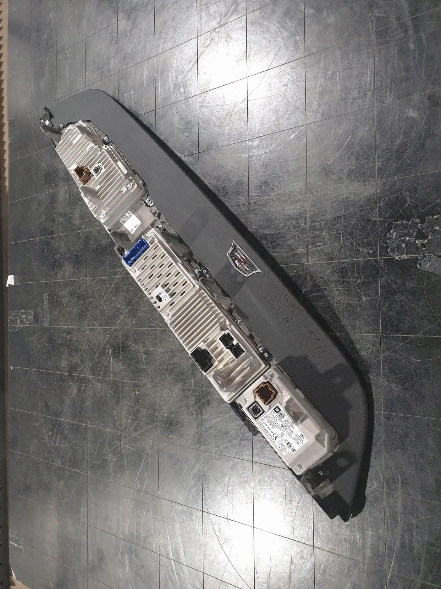
Click to zoom
Application Details
- Equipment Class
- DXX - Part 15 Low Power Communication Device Transmitter
- Date of Grant
- Jun 17, 2020
- Application Purpose
- Original Equipment
- Date of Application
- Jun 17, 2020
- Equipment Note
- CID (Central Information Display) system
- Frequency Range
- 13.56070000 - 13.56070000
- Company
- LG Electronics USA, Inc.
- Country
- United States
Documents & Files
Document Text
Text extracted from the exhibit documents filed with the FCC. Open a document above to read the original.
Users Manual
ICS User Manual GM V2 ICS CONFIDENTIAL NOT FOR DISTRIBUTION 1. Product overview and Specifications (1) Product overview 1) ICS(Integrated Center Stack)can not be used by itself. ICS is connected to Head Unit(CSM) in the vehicle, and it displays status and information of vehicle. 2) User can use the function of Head Unit by operating ICS. 3) ICS can not be connected to any other devices except for the Head Unit. 4) ICS has below additional function to help User interface for CSM .NFC .IR Proximity 5) ICS is part of the body with IPC(Cluster). (2) Specification Item Detail Spec. Product CAR Center Information Display Model COGD14FGA01 Display 16.9inch is ICS Screen Operating Voltage DC 12V (9V ~ 16V) Operating Temperature -40 °C ~ +85 °C CONFIDENTIAL NOT FOR DISTRIBUTION 16.9 inch (CID) 14.2 inch (Cluster) 7.2inch 7.2inch 14.2 inch 16.9 inch CONFIDENTIAL NOT FOR DISTRIBUTION 2. Feature list Items Specification Remark Display Screen Size 16.9’’ 0.141(H) x 0.141(V) mm Resolution 2940x 816 H x V Active Area 414.54x115.056mm H x V Luminance Min. 500 cd/m2 @Center 60% @+/-30degress(H) 32% @+/-45degress(H) Contrast Typ 10,000 @center >=14:1 ambient@5,000lux >=10:1 ambient@45,000lux Uniformity White ≥80% Area scan Color Gamut 100% Dimming Range 0 ~ 100% Touch Method Resolution 1024 x 540 MCU CPU Clock 24 MHz CAN Standard HS-CAN I/F Data rate up to 2 Mbit/s Video Interface Frame Rate 60Hz Color Depth 24bit Data Rate 3 [Gb/s] 2-Lane Interface FPD Link III Cable Length 10[M] STP Connector HSD (12pin) Video Interface (2-Lane) Main Connector (20pin) .Battery Power .CAN .Telltale Output -Main Connector Pin Assignment CONFIDENTIAL NOT FOR DISTRIBUTION Pin No Signal Name Function CN101_1 BATTERY Secondary Fused Battery Positive Voltage CN101_2 HSCAN+ AUTOSAR CAN Serial Data (+) CN101_3 HSCAN+ AUTOSAR CAN Serial Data (+) CN101_4 UART_RX NC CN101_5 GND GND CN101_6 HSCAN- AUTOSAR CAN Serial Data (-) CN101_7 HSCAN- AUTOSAR CAN Serial Data (-) CN101_8 UART_TX NC CN101_9 OUT 01 Air_Bag_RED (From IPC) CN101_10 OUT 02 ABS_AMBER (From IPC) CN101_11 OUT 03 Brake_USA_RED (From IPC) CN101_12 OUT 04 Brake_RED(From IPC) CN101_13 OUT 05 Preheat_AMBER(From IPC) CN101_14 OUT 06 Seatbelt_RED(From IPC) CN101_15 OUT 07 MIL_AMBER(From IPC) CN101_16 OUT 08 Pressure_AMBER(From IPC) CN101_17 OUT 09 ESC_OFF_AMBER(From IPC) CN101_18 OUT 10 ESC_AMBER(From IPC) CN101_19 LED DIM+ LED_PWR(From IPC) CN102_20 GND NC -HSD Connector (Video Interface) Pin Signal Name Function CN301_1 Pair Drain (A) From CSM CN301_2 DOUT +/RIN+ (A) From CSM CN301_3 DOUT -/RIN- (A) From CSM CN301_4 NC NC (Reserved for LVM) CN301_5 NC NC (Reserved for LVM) CN301_6 NC NC (Reserved for LVM) CN301_7 Pair Drain (B) From CSM CN301_8 DOUT +/RIN+ (B) From CSM CN301_9 DOUT -/RIN- (B) From CSM CN301_10 NC NC (Reserved for LVM) CN301_11 NC NC (Reserved for LVM) CN301_12 NC NC (Reserved for LVM) 3. External Connector 1) Do not use the product while driving. Please operate the product after stopping the car in a safe and legal manner. 2) Do not stare at the screen(monitor) while driving. While driving, staring at the screen (monitor) can be the cause of the accident. 3) Do not open the back cover in order to prevent the risk of electric shock. There is no user-serviceable part inside the product. Please request a repair to qualified service personnel. 4) Do not expose the product to water, rain, moisture in order to reduce the risk of fire or electric shock. 5) Please maintain a low enough volume that allow signal (such as emergency sirens) outside the vehicle to be easily heard. 6) Please be careful dropped or impact. 3. Cautions CONFIDENTIAL NOT FOR DISTRIBUTION FCC Information This device complies with part 15 of the FCC Results. Operation is subject to the following two conditions : (1) This Device may not cause harmful interface, and (2) This device must accept any interference received, including interference that may cause undesired operation. Note: This equipment has been tested and found to comply with the limits for CLASS B digital device, pursuant to Part 15 of FCC Rules. These limits are designed to provide reasonable protection against harmful interference when the equipment is operated in a commercial environment This equipment generates, uses and can radiate radio frequency energy and, if not installed and used in accordance with the instructions, may cause harmful interference to radio communications. However, there is no guarantee that interference will not occur in a particular installation. If this equipment does cause harmful interference to radio or television reception, which can be determined by turning the equipment off and on, the user is encouraged to try correct the interference by one or more of the following measures: 1.1. Reorient or relocate the receiving antenna. 1.2. Increase the separation between the equipment and receiver. 1.3. Connect the equipment into an outlet on a circuit different from that to which receiver is connected. 1.4. Consult the dealer or experienced radio/TV technician for help. WARNING Changes or modifications not expressly approved by the manufacturer could void the user’s authority to operate the equipment. “CAUTION : Exposure to Radio Frequency Radiation. Antenna shall be mounted in such a manner to minimize the potential for human contact during normal operation. The antenna should not be contacted during operation to avoid the possibility of exceeding the FCC radio frequency exposure limit. "ATTENTION: L'exposition aux rayonnements à fréquence radioélectrique. Antenne doit être montée de telle manière à minimiser le risque de contact humain pendant l'utilisation normale. L'antenne ne doit pas être contacté pendant le fonctionnement pour éviter la possibilité de dépasser la limite de l'exposition aux fréquences radio de la FCC. IC Information This device complies with Industry Canada license-exempt RSS standard(s). Operation in subject to The following two conditions: (1) this device may not cause interference, a…
Text truncated - open the document above for the full version.
Cover Letter(s)
Letter of Authorization Company : LG Electronics USA Address : 111 Sylvan Avenue, North Building, Englewood Cliffs, New Jersey, 07632, United States Product Name : CID (Central Information Display) system Model Number : COGD14FGA01 FCC Identifier : BEJ-COGD14FGA01 We authorize MiCOM Labs Inc, 575 Boulder Court, Pleasanton, California 94566, USA, to act on our behalf on all matters concerning the above named equipment. Any individual within MiCOM Labs is authorized to act on our behalf and take action on the application. We declare that MiCOM Labs Inc, 575 Boulder Court, Pleasanton, California 94566, USA, is allowed to forward all information related to the approval project to the Federal Communication Commission and to discuss any issues concerning the approval application. Any and all acts carried out by MiCOM Labs on our behalf shall have the same effect as acts of our own. Name: Kyung-Su, Han Date: June 12, 2020 Title: Director, Standards & Compliance Signature of applicant:
Cover Letter(s)
LG Electronics USA Office of Engineering Technology Federal Communications Commission 7435 Oakland Mills Road Columbia, MD 21046 Date: June 12, 2020 Subject; Request for Confidentiality FCC ID: BEJ-COGD14FGA01 To Whom It May Concern, Pursuant to the provisions of Sections 0.457 and 0.459 of Commission's rules (47CFR0.457, 0.459), we are requesting the Commission to withhold the following attachment(s) as confidential document from public disclosure indefinitely. • Schematic Diagram • Block Diagram • Part List • Operational Description Above mentioned document contains detailed system and equipment description are considered as proprietary information in operation of the equipment. The public disclosure of above documents might be harmful to our company and would give competitor an unfair advantage in the market. In additional to above mentioned documents, pursuant to Public Notice DA 04-1705 of the Commission' s policy, in order to comply with the marketing regulations in 47 CFT §2.803 and the importation rules in 47 CFR §2.1204, while ensuring that business sensitive information remains confidential until the actual marketing of newly authorized devices. We are requesting the commission to grant shot-term confidentiality request on the following attachment(s) for 180 days after the grant as outlined in Public Notice DA 04-1705. • External Photos • Internal Photos • Test Setup Photos • User Manual It is our understanding that all measurement test reports, FCC ID label format and correspondent during certification review process cannot be granted as confidential documents and those information will be available for public review once the grant of equipment authorization is issued. Sincerely, Signature: Name: Kyung-Su, Han Title: Director, Standards & Compliance
External Photos
Page 1 of 4 Page 2 of 4 Page 3 of 4 Page 4 of 4
Internal Photos
Page 1 of 13 FC NFC Antenna NFC Page 2 of 13 Page 3 of 13 NFC Page 4 of 13 Page 5 of 13 Page 6 of 13 Page 7 of 13 Page 8 of 13 Page 9 of 13 Page 10 of 13 Page 11 of 13 Page 12 of 13 Page 13 of 13 FPCB Antenna
Test Report
Page 1 of 21 Report No.: OT-206-RWD-022 It should not be reproduced except in full, without the written approval of ONETECH Corp. EMC-003 (Rev.2) ONETECH Corp.: 43-14, Jinsaegol-gil, Chowol-eup, Gwangju-si, Gyeonggi-do, 12735, Korea (TEL: 82-31-799-9500, FAX: 82-31-799-9599) ELECTROMAGNETIC EMISSION COMPLIANCE REPORT Test Report No. : OT-206-RWD-022 AGR No. : A206A-048 Applicant : LG Electronics USA Address : 111 Sylvan Avenue, North Building, Englewood Cliffs, New Jersey, 07632, United States Manufacturer : LG Electronics Inc. Address : 10, Magokjungang 10-ro, Gangseo-gu, Seoul, Korea Type of Equipment : CID (Central Information Display) system FCC ID : BEJ-COGD14FGA01 Model Name : COGD14FGA01 Multiple Model Name : N/A Serial number : N/A Total page of Report : 21 pages (including this page) Date of Incoming : June 03, 2020 Date of Issuing : June 12, 2020 SUMMARY The equipment complies with the requirements of FCC CFR 47 PART 15 SUBPART C Section 15.225 This test report contains only the result of a single test of the sample supplied for the examination. It is not a general valid assessment of the features of the respective products of the mass-production. Reviewed by: Approved by: Tae-Ho, Kim / Senior Manager Ki-Hong, Nam / Chief Engineer ONETECH Corp. ONETECH Corp. Page 2 of 21 Report No.: OT-206-RWD-022 It should not be reproduced except in full, without the written approval of ONETECH Corp. EMC-003 (Rev.2) ONETECH Corp.: 43-14, Jinsaegol-gil, Chowol-eup, Gwangju-si, Gyeonggi-do, 12735, Korea (TEL: 82-31-799-9500, FAX: 82-31-799-9599) CONTENTS Page 1. VERIFICATION OF COMPLIANCE ............................................................................................................................. 5 2. GENERAL INFORMATION ............................................................................................................................................ 6 2.1 TEST ITEMS AND RESULTS ............................................................................................................................................. 6 2.2 PRODUCT DESCRIPTION ................................................................................................................................................. 6 2.3 MODEL DIFFERENCES: .................................................................................................................................................. 6 2.4 RELATED SUBMITTAL(S) / GRANT(S) ............................................................................................................................ 6 2.5 PURPOSE OF THE TEST ................................................................................................................................................... 6 2.6 TEST METHODOLOGY .................................................................................................................................................... 6 2.7 TEST FACILITY ............................................................................................................................................................... 7 3. SYSTEM TEST CONFIGURATION ............................................................................................................................... 8 3.1 JUSTIFICATION ............................................................................................................................................................... 8 3.2 PERIPHERAL EQUIPMENT .............................................................................................................................................. 8 3.3 MODE OF OPERATION DURING THE TEST ...................................................................................................................... 8 3.4 EQUIPMENT MODIFICATIONS ........................................................................................................................................ 8 3.5 CONFIGURATION OF TEST SYSTEM ............................................................................................................................... 9 3.6 ANTENNA REQUIREMENT .............................................................................................................................................. 9 4. PRELIMINARY TEST ...................................................................................................................................................... 9 4.1 AC POWER LINE CONDUCTED EMISSIONS TESTS ......................................................................................................... 9 4.2 RADIATED EMISSIONS TESTS......................................................................................................................................... 9 5. FINAL RESULT OF MEASUREMENT ........................................................................................................................ 10 5.1 RADIATED EMISSION TEST .................................................................................................................................. 10 5.1.1 Operation frequency band: (13.553 ~ 13.567) MHz ............................................................................................ 10 5.1.2 Operation frequency band: Below 13.553 MHz and above 13.567 MHz ............................................................ 11 5.2 SPURIOUS EMISSION TEST ................................................................................................................................... 12 5.2.1 Spurious Radiated Emission Below 30 MHz ....................................................................................................... 12 5.3 20 DB BANDWIDTH .................................................................................................................................................. 16 5.3.1 Operating environment ........................................................................................................................…
Text truncated - open the document above for the full version.
Test Setup Photos
Page 1 of 2 - Radiated Emission Test Page 2 of 2
Contact Information
Applicant
David Kim(Team leader, LGEUS NA Policy & Regulatory Affairs)
Technical Contact
Test Firm
ONETECH Corp.Ki Hong Nam
Technical Specifications
| # | Rule Parts | Frequency Range | Power Output |
|---|---|---|---|
| 1 | 15C | 13.5607 MHz - 13.5607 MHz | - |
Other Applications from LG Electronics USA, Inc.

BEJTFHOBINI1F1
Jan 08, 2025Telematics
Equipment Class
DTS - Digital Transmission SystemBEJNT-16Z90TS
Oct 02, 2024Notebook Computer
Equipment Class
DSS - Part 15 Spread Spectrum TransmitterBEJSP-PEW8
Sep 26, 2024Stylus Pen
Equipment Class
DCD - Part 15 Low Power Transmitter Below 1705 kHzBEJ-RSMV2
Sep 24, 2024RF Module
Equipment Class
FDS - Part 15 Field Disturbance SensorBEJTFBMEIBN3EU
Sep 24, 2024Telematics
Equipment Class
NII - Unlicensed National Information Infrastructure TX