BEJ-LW-9880Cellular Modem
LG Electronics USA, Inc.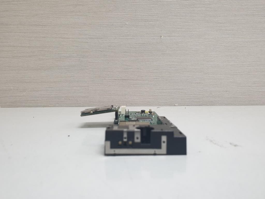
Click to zoom
Application Details
- Equipment Class
- PCB - PCS Licensed Transmitter
- Date of Grant
- Jan 05, 2020
- Application Purpose
- Original Equipment
- Date of Application
- Jan 05, 2020
- Equipment Note
- Cellular Modem
- Frequency Range
- 699.00000000 - 716.00000000
- Company
- LG Electronics USA, Inc.
- Country
- United States
Documents & Files
Document Text
Text extracted from the exhibit documents filed with the FCC. Open a document above to read the original.
Users Manual
LTE / WCDMA Wireless Module Cellular modem_LW-9880 Product Manual This document has been submitted under terms of Non-Disclosure Agreement. By accepting deliver of this document, the recipient acknowledges and agrees that: i) the recipient will use this document only for the purpose for which it has been supplied; ii) the recipient will not disclose this information to anyone not covered by our mutual NDA; and iii) all the information contained herein will be treated as strictly confidential material." Copyright© LG Electronics Inc Co., Ltd. All Right Reserved Revision History Revision Date Authors Description V1.0 04/20/19 Sung il Jeon Initial Version Copyright© LG Electronics Inc Co., Ltd. All Right Reserved Table of Contents Table of Contents .................................................................................................................................... 3 1. Executive Summary ......................................................................................................................... 4 1.1. Device Introduction ...................................................................................................................................................4 2. Electrical Specifications ................................................................................................................... 4 2.1. General Specifications .........................................................................................................................................4 2.2. HW Specifications ......................................................................................................................................................4 2.3. Environmental Specifications .................................................................................................................................6 3. Mechanical Specifications................................................................................................................ 6 3.1. Mechanical Appearance ..........................................................................................................................................6 3.1.1. Mechanical Dimensions ......................................................................................................... 7 4. Block Diagram Architecture ............................................................................................................. 8 5. Cellular modem_LW-9880 Interface ................................................................................................ 8 5.1 Application Note of Cellular modem_LW-9880 Interface ..........................................................................8 5.1.1 Power Supply .......................................................................................................................... 8 5.1.2 UART Signal ............................................................................................................................ 9 5.1.3 USB Interface ........................................................................................................................ 10 5.1.4 E-SIM Interface ..................................................................................................................... 10 6. PCB Layout Guide ......................................................................................................................... 11 6.1. PCB Layout ................................................................................................................................................................. 11 7. Antenna Approved Source ............................................................................................................. 11 7.1 Description .................................................................................................................................................................. 11 7.2 Electrical Properties ................................................................................................................................................. 12 7.2.1 Specification ........................................................................................................................... 12 7.2.2 Impedance` ............................................................................................................................. 12 7.2.2.1 Nominal Impedance .............................................................................................................. 12 7.2.2.2 Measuring Method ............................................................................................................... 12 7.2.2.3 Directive ness .................................................................................................................... 12 7.2.2.4 Gain( Free Space) ............................................................................................................. 13 7.2.2.5 Radiation Pattern (XY-Plane) ................................................................................................ 13 Copyright© LG Electronics Inc Co., Ltd. All Right Reserved 1. Executive Summary 1.1. Device Introduction Cellular modem_LW-9880 is a telecommunication (ELS61_US-R2) modem module that supports LTE / WCDMA with up to 10.2Mbps download, and 5.2Mbps upload. 2. Electrical Specifications 2.1. General Specifications Main chipset Intel XMM7160 Memory 1Gbit LPDDR2 SDRAM Interface Type High-speed USB 2.0 UART serial interface Common Air interface FDD LTE / WCDMA Frequency band (FDD LTE & WCDMA) LTE Band 2, 4, 5, 12 / WCDMA 2, 4, 5 DC input operating voltage Typical Input 5V, DC Converter output 3.8V Maximum current @ +5VDC, Maximum TX Power (23dBm) Under 1 A Dimensions 140.0 x 45.0 x 13.8mm Operating temperature(board temperature) Normal operation: -30°C to +85°C Extended operation: -40°C to +90°C Table 2-1 General Specifications 2.2. HW Specifications ITEM SPECIFICATION LTE Standard 3…
Text truncated - open the document above for the full version.
Cover Letter(s)
LG Electronics USA 1000 Sylvan Avenue Englewood Cliffs, New Jersey, United States September 11, 2019 Federal Communications Commission Authorization and Evaluation Division 7435 Oakland Mills Road, Columbia, MD 21046 Request of Confidentiality FCC ID: BEJ-LW-9880 To Whom It May Concern: Pursuant to Sections 0.457 and 0.459 of the Commission’s Rules (CFR 47), and Section 552 (b) (4) of the Freedom of Information Act, LG Electronics USA hereby requests confidentiality and treatment of certain information accompanying this application. The materials contain trade secrets and proprietary information not customarily released to the public. The public disclosure of these matters might be harmful to the Applicant and provide unjustified benefits to its competitors. We are also hereby request Short-Term Confidentiality for 180 days after the grant as outlined in Public Notice DA 04-1705. This provision will give LG Electronics Inc. temporary confidentiality of commercially sensitive information prior to product release. CONFIDENTIAL LIST Permanent 1 Block Diagram 2 Operational Descriptions 3 Schematics 4 Part List 5 Tune-up Procedure Short-Term 6 External Photos 7 Internal Photos 8 Test-Setup Photos 9 User’s Manual The requested Permanent and Temporary Confidential exhibits are listed as follows: Sincerely Yours Mr. Kyung-su Han Director, NA Regulatory and Environmental Affairs LG Electronics USA, Inc. Phone: 201-472-2623
Cover Letter(s)
LG Electronics USA 1000 Sylvan Avenue Englewood Cliffs, New Jersey, United States September 11, 2019 Federal Communications Commission Authorization and Evaluation Division 7435 Oakland Mills Road, Columbia, MD 21046 LETTER FOR AUTHORIZATION FCC ID: BEJ-LW-9880 To whom it may concern: I, the undersigned, hereby authorize Lab Manager Hyunchae, You (or Jungmin, Yang) and of SGS Korea Co., Ltd. and hereafter referred to as SGS Korea, to act on our behalf in all manners relating to application for equipment authorization, including signing of all documents relating to these matters. Any and all acts carried out by Lab Manager Hyunchae, You (or Jungmin, Yang) of SGS Korea Co., Ltd. on our behalf shall have the same effect as acts of our own. I, the undersigned, hereby certify that we are not subject to a denial of federal benefits, that includes FCC benefits, pursuant to Section 5301 of the Anti‐Drug Abuse Act of 1988, 21 U.S.C. 853(a) . In authorizing SGS Korea as our agent, we still recognize that we are responsible to: a) comply with the relevant provisions of the certification program; b) make all necessary arrangements for the conduct of the evaluation, including provision for examining documentation and access to all areas, records (including internal audit reports) and personnel for the purposes of evaluation (e.g. testing, inspection, assessment, surveillance, reassessment) and resolution of complaints; c) make claims regarding certification only in respect of the scope for which certification has been granted; d) do not use our product certification in such a manner as to bring the Certification Division into disrepute and not make any statement regarding our product certification which the Certification Division may consider misleading or unauthorized; e) upon suspension or cancellation of certification, discontinue use of all advertising matter that contains any reference thereto and return any certification documents as required by the Certification Division; LG Electronics USA 1000 Sylvan Avenue Englewood Cliffs, New Jersey, United States LG Electronics USA 1000 Sylvan Avenue Englewood Cliffs, New Jersey, United States f) use certification only to indicate the products are certified as being in conformity with specified standards; g) endeavor to ensure that no certificate or report nor any part thereof is used in a misleading manner; h) ensure that any reference to our product certification in communication media such as documents, brochures or advertising, complies with the requirements of the Certification Division; i) keep a record of all complaints made known to the us relating to the product’s compliance with requirements of the relevant standard and to make these records available to the Certification Division when requested; j) take appropriate action with respect to such complaints and any deficiencies found in products or services that affect compliance with the requirements for certification; k) document the actions taken. This authorization is valid until further written notice from the applicant. Sincerely Yours Mr. Kyung-Su Han Director, NA Regulatory and Environmental Affairs LG Electronics USA, Inc. Phone: 201-472-2623
Cover Letter(s)
Cover Letter-Modular Approval FCC ID: BEJ-LW-9880 Date: September 11, 2019 Gentlemen: There’s an LW-9880 that would like to have your authorization as a modular approval. The specific product as below, LW-9880 with its designed features and specified description, meets special requirements for Full modular approval on FCC KDB996369 by cross-reference list below. Company LG Electronics USA, Inc. Model Name LW-9880 Model Number LW-9880 FCC ID BEJ-LW-9880 Requirement of FCC KDB996369 Comply(Y/N) 1. The modular transmitter must have its own RF shielding. Y The EUT provides the RF shielding. See EUT photo. 2. The modular transmitter must have buffered modulation/data inputs (if such inputs are provided) to ensure that the module will comply with Part 15 requirements under conditions of excessive data rates or over-modulation. Y The EUT has its buffered modulation. Please see the Schematic Diagram. 3. The modular transmitter must have its own power supply regulation. Y The EUT has its own power supply regulation, please see the Schematic Diagram. 4. The modular transmitter must comply with the antenna and transmission system requirements of Sections 15.203, 15.204(b) and 15.204(c). The antenna must either be permanently attached or employ a “unique” antenna coupler (at all connections between the module and the antenna, including the cable). The “professional installation” provision of Section 15.203 is not applicable to modules but can apply to limited modular approvals under paragraph (b) of this section. Y The EUT meets the FCC antenna requirements; unique antenna connector and photo of antenna are shown in the test report. 5. The modular transmitter must be tested in a stand‐alone configuration, i.e., the module must not be inside another device during testing. Y The EUT was tested with a test board, Please see test report and setup photo 6. The modular transmitter must be labeled with its own FCC ID number, and, if the FCC ID is not visible when the module is installed inside another device, then the outside of the device into which the module is installed must also display a label referring to the enclosed module. This exterior label can use wording such as the following: “Contains Transmitter Module FCC ID: BEJ-LW-9880” or “Contains FCC ID: BEJ-LW-9880” Any similar wording that expresses the same meaning may be used. The Grantee may either provide such a label, an example of which must be included in the application for equipment authorization, or, must provide adequate instructions along with the module which explain this requirement. In the latter case, a copy of these instructions must be included in the application for equipment authorization. Y Please see exhibition label sample for the FCC ID of this module. And also in the exhibition Users manual, there are instructions give to the OEM on how to label the end product. 7. The modular transmitter must comply with any specific rule or operating requirements applicable to the transmitter and the manufacturer must provide adequate instructions along with the module to explain any such requirements. A copy of these instructions must be included in the application for equipment authorization. Y The EUT is compliant with all applicable FCC rules. Details instructions for maintaining compliance are give in the User Manual. 8. The modular transmitter must comply with any applicable RF exposure requirements. For example, FCC Rules in Sections 2.1091, 2.1093 and specific Sections of Part 15, including 15.319(i), 15.407(f), 15.253(f) and 15.255(g), require that Unlicensed PCS, UNII and millimeter wave devices perform routine environmental evaluation for RF Exposure to demonstrate compliance. In addition, spread spectrum transmitters operating under Section 15.247 are required to address RF Exposure compliance in accordance with Section Y The EUT complies with RF exposure requirement. 15.247(b)(4). Thank you. Sincerely, By: __________________________ Kyung-Su Han (Signature 1 ) (Print name) Title: Director, NA Regulatory and Environmental Affairs On behalf of: LG Electronics USA, Inc. (Company Name) Telephone: 201-472-2623
External Photos
External photos of EUT Top view of EUT Bottom view of EUT Side view of EUT
ID Label/Location Info
Label Information <Topof EUT> ModelName:LW-9880 Brand : LG FCCID:BEJ-LW-9880 IC:2703N-LW9880
Internal Photos
Internal photo of EUT Top view of Main PCB Bottom view of Main PCB View of module View of antenna WWAN Module Transmitter Antenna Receiver Antenna
Test Report
Report Number: F690501/RF-RTL014355-1 Page: 2 of 254 The results of this test report are effective only to the items tested. The SGS Korea is not responsible for the sampling, the results of this test report apply to the sample as received. This test report cannot be reproduced, except in full, without prior written permission of the Company. This test report does not assure KOLAS accreditation. SGS Korea Co., Ltd. (Gunpo Laboratory) 4, LS-ro 182beon-gil, Gunpo-si, Gyeonggi-do, Korea, 15807 http://www.sgsgroup.kr RTT5041-19(2019.04.24)(1) Tel. +82 31 428 5700 / Fax. +82 31 427 2370 A4(210 mmx297 mm) TABLE OF CONTENTS Page 1. General Information ---------------------------------------------------------------------------------------- -3 2. RF Radiated Output Power & Spurious Radiated Emission ------------------------------------- -8 3. Conducted Output Power --------------------------------------------------------------------------------- -48 4. Occupied Bandwidth --------------------------------------------------------------------------------------- -53 5. Peak-Average Ratio ---------------------------------------------------------------------------------------- 119 6. Spurious Emissions at Antenna Terminal ------------------------------------------------------------ -154 7. Band Edge ---------------------------------------------------------------------------------------------------- 205 8. Frequency Stability ----------------------------------------------------------------------------------------- 248 Report Number: F690501/RF-RTL014355-1 Page: 3 of 254 The results of this test report are effective only to the items tested. The SGS Korea is not responsible for the sampling, the results of this test report apply to the sample as received. This test report cannot be reproduced, except in full, without prior written permission of the Company. This test report does not assure KOLAS accreditation. SGS Korea Co., Ltd. (Gunpo Laboratory) 4, LS-ro 182beon-gil, Gunpo-si, Gyeonggi-do, Korea, 15807 http://www.sgsgroup.kr RTT5041-19(2019.04.24)(1) Tel. +82 31 428 5700 / Fax. +82 31 427 2370 A4(210 mmx297 mm) 1. General Information 1.1. Testing Laboratory SGS Korea Co., Ltd. (Gunpo Laboratory) - 10-2, LS-ro 182beon-gil, Gunpo-si, Gyeonggi-do, Korea, 15807 - 4, LS-ro 182beon-gil, Gunpo-si, Gyeonggi-do, Korea, 15807 - Designation number: KR0150 All SGS services are rendered in accordance with the applicable SGS conditions of service available on request and accessible at http://www.sgs.com/en/Terms-and-Conditions.aspx. Phone No. : +82 31 688 0901 Fax No. : +82 31 688 0921 1.2. Details of Applicant FCC Applicant : LG Electronics USA FCC Address : 1000 Sylvan Avenue, Englewood Cliffs, New Jersey, United States, 07632 IC Applicant : LG Electronics Inc. IC Address : 170, Seongsanpaechong-ro, Seongsan-gu, Changwon-si, Gyeongsangnam-do 51533, Korea (Republic of) Contact Person : Han, Kyung-su Phone No. : +2 201 472 2623 1.3. Details of Manufacturer Company : LG Electronics Inc. Address : 170, Seongsanpaechong-ro, Seongsan-gu, Changwon-si, Gyeongsangnam-do 51533, Korea (Republic of) Report Number: F690501/RF-RTL014355-1 Page: 4 of 254 The results of this test report are effective only to the items tested. The SGS Korea is not responsible for the sampling, the results of this test report apply to the sample as received. This test report cannot be reproduced, except in full, without prior written permission of the Company. This test report does not assure KOLAS accreditation. SGS Korea Co., Ltd. (Gunpo Laboratory) 4, LS-ro 182beon-gil, Gunpo-si, Gyeonggi-do, Korea, 15807 http://www.sgsgroup.kr RTT5041-19(2019.04.24)(1) Tel. +82 31 428 5700 / Fax. +82 31 427 2370 A4(210 mmx297 mm) 1.4. Description of EUT Kind of Product Cellular Modem Model Name LW-9880 Power Supply DC 5.0 V Rated Power LTE Band 2, 4, 5, 12: 22.5 ㏈m Frequency Range LTE Band 2: 1 850 ㎒ ~ 1 910 ㎒ LTE Band 4: 1 710 ㎒ ~ 1 755 ㎒ LTE Band 5: 824 ㎒ ~ 849 ㎒ LTE Band 12: 699 ㎒ ~ 716 ㎒ Emission Designator LTE Band 2 (1.4 ㎒): 1M11G7D (QPSK) / 1M11W7D (16QAM) LTE Band 2 (3 ㎒): 2M69G7D (QPSK) / 2M69W7D (16QAM) LTE Band 2 (5 ㎒): 4M53G7D (QPSK) / 4M53W7D (16QAM) LTE Band 2 (10 ㎒): 8M97G7D (QPSK) / 8M97W7D (16QAM) LTE Band 2 (15 ㎒): 13M6G7D (QPSK) / 13M6W7D (16QAM) LTE Band 2 (20 ㎒): 18M0G7D (QPSK) / 18M1W7D (16QAM) LTE Band 4 (1.4 ㎒): 1M10G7D (QPSK) / 1M12W7D (16QAM) LTE Band 4 (3 ㎒): 2M70G7D (QPSK) / 2M69W7D (16QAM) LTE Band 4 (5 ㎒): 4M52G7D (QPSK) / 4M53W7D (16QAM) LTE Band 4 (10 ㎒): 8M97G7D (QPSK) / 8M97W7D (16QAM) LTE Band 4 (15 ㎒): 13M6G7D (QPSK) / 13M5W7D (16QAM) LTE Band 4 (20 ㎒): 18M0G7D (QPSK) / 18M0W7D (16QAM) LTE Band 5 (1.4 ㎒): 1M10G7D (QPSK) / 1M11W7D (16QAM) LTE Band 5 (3 ㎒): 2M69G7D (QPSK) / 2M68W7D (16QAM) LTE Band 5 (5 ㎒): 4M53G7D (QPSK) / 4M52W7D (16QAM) LTE Band 5 (10 ㎒): 8M97G7D (QPSK) / 8M97W7D (16QAM) LTE Band 12 (1.4 ㎒): 1M10G7D (QPSK) / 1M11W7D (16QAM) LTE Band 12 (3 ㎒): 2M69G7D (QPSK) / 2M69W7D (16QAM) LTE Band 12 (5 ㎒): 4M52G7D (QPSK) / 4M53W7D (16QAM) LTE Band 12 (10 ㎒): 9M00G7D (QPSK) / 8M97W7D (16QAM) Modulation Technique QPSK, 16QAM Antenna Type Internal antenna Antenna gain 699 ㎒ ~ 716 ㎒: 0.99 ㏈i 824 ㎒ ~ 849 ㎒: -1.03 ㏈i 1 710 ㎒ ~ 1 755 ㎒: 3.56 ㏈i 1 850 ㎒ ~ 1 910 ㎒: 3.62 ㏈i Report Number: F690501/RF-RTL014355-1 Page: 5 of 254 The results of this test report are effective only to the items tested. The SGS Korea is not responsible for the sampling, the results of this test report apply to the sample as received. This test report cannot be reproduced, except in full, without prior written permission of the Company. This test report does not assure KOLAS accreditation. SGS Korea Co., Ltd. (Gunpo Laboratory) 4, LS-ro 182beon-gil, Gunpo-si, Gyeonggi-do, Korea, 15807 http://www.sgsgroup.kr RTT5041-19(2019.04.24)(1) Tel. +82 31 428 5700 / Fax. +82 31 427 2370 A4(210 mmx297 mm) 1.5. Test Equipment List Equipment Manufacturer Model S/N Cal. Date Cal. Interval Cal. Due Signal Generator Agilent E8257D MY51501169 Jul. 03, 2019 Annual Jul. 03, …
Text truncated - open the document above for the full version.
Test Report
Report Number: F690501/RF-RTL014355-1 Page: 53 of 254 The results of this test report are effective only to the items tested. The SGS Korea is not responsible for the sampling, the results of this test report apply to the sample as received. This test report cannot be reproduced, except in full, without prior written permission of the Company. This test report does not assure KOLAS accreditation. SGS Korea Co., Ltd. (Gunpo Laboratory) 4, LS-ro 182beon-gil, Gunpo-si, Gyeonggi-do, Korea, 15807 http://www.sgsgroup.kr RTT5041-19(2019.04.24)(1) Tel. +82 31 428 5700 / Fax. +82 31 427 2370 A4(210 mmx297 mm) 4. Occupied Bandwidth 4.1. Limit CFR 47, Section FCC §2.1049 and IC RSS-Gen Issue 5 6.7. 4.2. Test Procedure FCC The test follows section 5.4.4 of ANSI C63.26-2015. a. The spectrum analyzer center frequency is set to the nominal EUT channel center frequency. The frequency span for the spectrum analyzer shall be set wide enough to capture all modulation. products including the emission skirts (typically a span of 1.5 × OBW is sufficient). b. The nominal IF filter 3 ㏈ bandwidth (RBW) shall be in the range of 1 % to 5 % of the anticipated OBW, and the VBW shall be set ≥ 3 × RBW. c. Set the reference level of the instrument as required to prevent the signal amplitude from exceeding the maximum spectrum analyzer input mixer level for linear operation. See guidance provided in 4.2.3. d. Set the detection mode to peak, and the trace mode to max-hold. e. If the instrument does not have a 99 % OBW function, recover the trace data points and sum directly in linear power terms. Place the recovered amplitude data points, beginning at the lowest frequency, in a running sum until 0.5 % of the total is reached. Record that frequency as the lower OBW frequency. Repeat the process until 99.5 % of the total is reached and record that frequency as the upper OBW frequency. The 99 % power OBW can be determined by computing the difference these two frequencies. f. The OBW shall be reported and plot(s) of the measuring instrument display shall be provided with the test report. The frequency and amplitude axis and scale shall be clearly labeled. Tabular data can be reported in addition to the plot(s). Report Number: F690501/RF-RTL014355-1 Page: 54 of 254 The results of this test report are effective only to the items tested. The SGS Korea is not responsible for the sampling, the results of this test report apply to the sample as received. This test report cannot be reproduced, except in full, without prior written permission of the Company. This test report does not assure KOLAS accreditation. SGS Korea Co., Ltd. (Gunpo Laboratory) 4, LS-ro 182beon-gil, Gunpo-si, Gyeonggi-do, Korea, 15807 http://www.sgsgroup.kr RTT5041-19(2019.04.24)(1) Tel. +82 31 428 5700 / Fax. +82 31 427 2370 A4(210 mmx297 mm) IC The following conditions shall be observed for measuring the occupied bandwidth and x ㏈ bandwidth: • The transmitter shall be operated at its maximum carrier power measured under normal test conditions. • The span of the spectrum analyzer shall be set large enough to capture all products of the modulation process, including the emission skirts, around the carrier frequency, but small enough to avoid having other emissions (e.g. on adjacent channels) within the span. • The detector of the spectrum analyzer shall be set to “Sample”. However, a peak, or peak hold, may be used in place of the sampling detector since this usually produces a wider bandwidth than the actual bandwidth (worst-case measurement). Use of a peak hold (or “Max Hold”) may be necessary to determine the occupied / x ㏈ bandwidth if the device is not transmitting continuously. • The resolution bandwidth (RBW) shall be in the range of 1% to 5% of the actual occupied / x ㏈ bandwidth and the video bandwidth (VBW) shall not be smaller than three times the RBW value. Video averaging is not permitted. Note: It may be necessary to repeat the measurement a few times until the RBW and VBW are in compliance with the above requirement. For the 99% emission bandwidth, the trace data points are recovered and directly summed in linear power level terms. The recovered amplitude data points, beginning at the lowest frequency, are placed in a running sum until 0.5% of the total is reached, and that frequency recorded. The process is repeated for the highest frequency data points (starting at the highest frequency, at the right side of the span, and going down in frequency). This frequency is then recorded. The difference between the two recorded frequencies is the occupied bandwidth (or the 99% emission bandwidth). EUT Directional Coupler Mobile Test Unit Spectrum Analyzer Report Number: F690501/RF-RTL014355-1 Page: 55 of 254 The results of this test report are effective only to the items tested. The SGS Korea is not responsible for the sampling, the results of this test report apply to the sample as received. This test report cannot be reproduced, except in full, without prior written permission of the Company. This test report does not assure KOLAS accreditation. SGS Korea Co., Ltd. (Gunpo Laboratory) 4, LS-ro 182beon-gil, Gunpo-si, Gyeonggi-do, Korea, 15807 http://www.sgsgroup.kr RTT5041-19(2019.04.24)(1) Tel. +82 31 428 5700 / Fax. +82 31 427 2370 A4(210 mmx297 mm) 4.3 Test Results Ambient temperature : (23 ± 1) °C Relative humidity : 47 % R.H. Band Mode Frequency (㎒) Occupied Bandwidth (㎒) 2 (1.4 ㎒) QPSK 1 850.7 1.107 1 880.0 1.107 1 909.3 1.111 2 (1.4 ㎒) 16QAM 1 850.7 1.103 1 880.0 1.107 1 909.3 1.111 2 (3 ㎒) QPSK 1 851.5 2.692 1 880.0 2.692 1 908.5 2.692 2 (3 ㎒) 16QAM 1 851.5 2.692 1 880.0 2.683 1 908.5 2.692 2 (5 ㎒) QPSK 1 852.5 4.515 1 880.0 4.530 1 907.5 4.501 2 (5 ㎒) 16QAM 1 852.5 4.501 1 880.0 4.515 1 907.5 4.530 2 (10 ㎒) QPSK 1 855.0 8.944 1 880.0 8.973 1 905.0 8.973 2 (10 ㎒) 16QAM 1 855.0 8.944 1 880.0 8.973 1 905.0 8.973 2 (15 ㎒) QPSK 1 857.5 13.502 1 880.0 13.632 1 902.5 13.546 2 (15 ㎒) 16QAM 1 857.5 13.589 1 880.0 13.589 1 902.5 13.546 2 (20 ㎒) QPSK 1 86…
Text truncated - open the document above for the full version.
Test Report
Report Number: F690501/RF-RTL014355-1 Page: 119 of 254 The results of this test report are effective only to the items tested. The SGS Korea is not responsible for the sampling, the results of this test report apply to the sample as received. This test report cannot be reproduced, except in full, without prior written permission of the Company. This test report does not assure KOLAS accreditation. SGS Korea Co., Ltd. (Gunpo Laboratory) 4, LS-ro 182beon-gil, Gunpo-si, Gyeonggi-do, Korea, 15807 http://www.sgsgroup.kr RTT5041-19(2019.04.24)(1) Tel. +82 31 428 5700 / Fax. +82 31 427 2370 A4(210 mmx297 mm) 5. Peak-Average Ratio 5.1. Limit FCC - §22.913(d) Measurement of the ERP of Cellular base transmitters and repeaters must be made using an average power measurement technique. The peak-to-average ratio (PAR) of the transmission must not exceed 13 ㏈. - §24.232(d), power measurements for transmissions by stations authorized under this section may be made either in accordance with a Commission-approved average power technique or in compliance with paragraph (e) of this section. In both instances, equipment employed must be authorized in accordance with the provisions of §24.51. In measuring transmissions in this band using an average power technique, the peak-to-average ratio (PAR) of the transmission may not exceed 13 ㏈. - §27.50(d)(5), power measurements for transmissions by stations authorized under this section may be made either in accordance with a Commission-approved average power technique or in compliance with paragraph (d)(6) of this section. In measuring transmissions in this band using an average power technique, the peak-to-average ratio (PAR) of the transmission may not exceed 13 ㏈. IC - RSS-130 Issue 2 4.6.1, the peak-to-average power ratio (PAPR) of the transmitter shall not exceed 13 ㏈ for more than 0.1 % of the time and shall use a signal corresponding to the highest PAPR during periods of continuous transmission . - RSS-132 Issue 3 5.4, the peak-to-average power ratio (PAPR) of the transmitter shall not exceed 13 ㏈ for more than 0.1 % of the time using a signal corresponding to the highest PAPR during periods of continuous transmission. - RSS-133 Issue 6 6.4, the transmitter’s peak-to-average power ratio (PAPR) shall not exceed 13 ㏈ for more than 0.1 % of the time using a signal corresponding to the highest PAPR during periods of continuous transmission. - RSS-139 Issue 3 6.5, the peak to average power ratio (PAPR) of the equipment shall not exceed 13 ㏈ for more than 0.1 % of the time, using a signal that corresponds to the highest PAPR during periods of continuous transmission. Report Number: F690501/RF-RTL014355-1 Page: 120 of 254 The results of this test report are effective only to the items tested. The SGS Korea is not responsible for the sampling, the results of this test report apply to the sample as received. This test report cannot be …
Text truncated - open the document above for the full version.
Contact Information
Applicant
David Kim(Team leader, LGEUS NA Policy & Regulatory Affairs)
Technical Contact
SGS Korea Co., LtdHyunchae You
[email protected]82-31-688-0902
4, LS-ro, 182 beon-gil · Gunpo-si · South Korea
Non-Technical Contact
SGS Korea Co., LtdSoYoung Gong
[email protected]82-31-428-5827
Test Firm
SGS Korea Co., LtdHwang Gihee
Technical Specifications
| # | Rule Parts | Frequency Range | Power Output | Emission | Tolerance |
|---|---|---|---|---|---|
| 16 | 27 | 699 MHz - 716 MHz | 31.00 mW | 8M97W7D | 2.5 ppm |
Other Applications from LG Electronics USA, Inc.

BEJTFHOBINI1F1
Jan 08, 2025Telematics
Equipment Class
DTS - Digital Transmission SystemBEJNT-16Z90TS
Oct 02, 2024Notebook Computer
Equipment Class
DSS - Part 15 Spread Spectrum TransmitterBEJSP-PEW8
Sep 26, 2024Stylus Pen
Equipment Class
DCD - Part 15 Low Power Transmitter Below 1705 kHzBEJ-RSMV2
Sep 24, 2024RF Module
Equipment Class
FDS - Part 15 Field Disturbance SensorBEJTFBMEIBN3EU
Sep 24, 2024Telematics
Equipment Class
NII - Unlicensed National Information Infrastructure TX