BEJ-WL1SB23Wireless Audio Module
LG Electronics USA, Inc.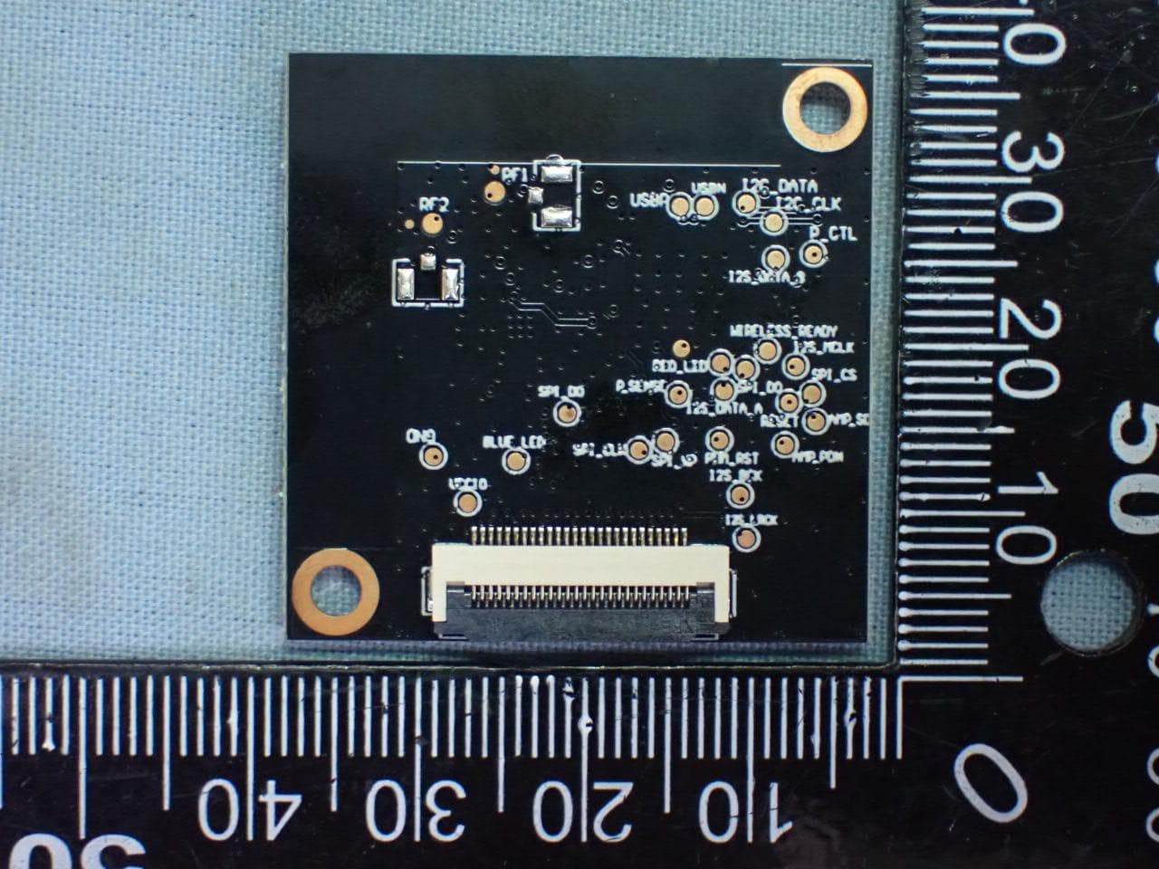
Click to zoom
Application Details
- Equipment Class
- NII - Unlicensed National Information Infrastructure TX
- Date of Grant
- Aug 26, 2023
- Application Purpose
- Original Equipment
- Date of Application
- Aug 26, 2023
- Equipment Note
- Wireless Audio Module
- Frequency Range
- 5730.00000000 - 5845.00000000
- Company
- LG Electronics USA, Inc.
- Country
- United States
Documents & Files
Document Text
Text extracted from the exhibit documents filed with the FCC. Open a document above to read the original.
Users Manual
1 User Manual Product name: Wireless Audio Module Product Model: WL1SB23 Document No: 2 1. General specifications WL1SB23 is based on IA9QH5 chipset that complied with 5.2/5.8GHz ISM Band,and it is the small size and low power module for Wireless Audio. IA9QH5 is a system-on-chip (SOC) designed for low-power and low-cost applications. It is a highly integrated single chip transceiver, supporting multiple audio interfaces such as I2S, S/PDIF, and USB. IA9QH5 provides dual transmitter and receiver modes, which enables the seamless and bi-directional transmission of high quality audio. In the transmitter, Tx receives digitized stereo as input, which is packetized and processed for synchronization and data integrity. In the receiver, Rx receives RF signal, demodulated and processed to restore the transmitted signal, and then streamed as digital audio output. ■ Digital I2S audio interface ■ Size : 35mm x 35mm x 4.43 mm ■ PCB Pattern Antenna ■ RF Freq.(MHz) : 5160 - 5245MHz、5730 - 5845MHz [CE/UKCA only used 5.8GHz] ■ Modulation Technique :GFSK ■ Crystal : 40MHz, 16PF, ±10PPM ■ Short delay time variation ■ Low Power Consumption ■ operating temperature 0ºC ~ 60ºC ■ working voltage 3.3V±0.15V Block diagram Note: Frequencies of this transmitter 5160-5245MHz & 5730-5845MHz. Note: CE/UKCA only used 5730-5845MHz. 3 2. The application UI WL1SB23 Operation description First: the module is powered on and started by 3.3V; Second: the host transmits the audio signal to the module through I2S; Third: THE IA9QH5 on the module decodes the I2S audio signal. Fourth: the IA9QH5 RF chip on the module transmits the audio through wireless transmission; Fifth: there is I2C communication between the module and the host, both sides obtain the status and control through I2C; The product automatically stops the transmission if the information fails to be transferred or the operation fails. WL1SB23 as the main device WL2SB23 Operation description First: The module is powered on and started by 3.3V; Second: The IA9QH5 RF chip on the module receives the audio signal transmitted by the transmitting module through wireless transmission; Third: MCU IA9QH5 decodes the acquired audio signal and transmits the audio to the power amplifier on the subwoofer power amplifier board through I2S; Fourth: There is I2C communication between the module and the subwoofer power amplifier board, initializing the power amplifier on the subwoofer power amplifier board, and IO port communication between the module and the subwoofer power amplifier board, controlling the power amplifier switch and LED state display. WL2SB23 is a client device controlled by the WL1SB23. WL1SB23 device is classified as a master device. WL2SB23 is classified as a Client device under the control of the WL1SB23. The product automatically stops the transmission if the information fails to be transferred or the operation fails. ISED RSS-247 (6.4) required by the technology When there is no information to transmit or an operation fails, the device automatically discontinue transmission. After the transmission is discontinued, the TX module enters the reconnection state until it is reconnected or the power supply is switched off passively. After the transmission is discontinued, the RX module enters the RE-connection state for one minute, IF no connection, enters the standby mode after one minute. FCC 15.407 (c) required by the technology The device would automatically discontinue transmission if there is no information to transmit or if the operation fails. After the transmission is discontinued, the TX module enters the reconnection state until it is reconnected or the power supply is switched off passively. After the transmission is discontinued, the RX module enters the RE-connection state for one minute, IF no connection, enters the standby mode after one minute. WL1SB23 (TX module): The reconnection state is TX will transmit control signal to RX for pair each other. The TX re-try to transmit control signal to RX on complete frame or burst intervals until they connect successfully or power supply be off passively. WL2SB23 (RX module): The connection state is no transmit data by RX module. It’s only permit to transmit the information that is repetitive codes to TX on complete frame or burst intervals. The standby mode is enter sleep mode to save consumption power. On this mode, the RX doesn’t transmit any information or data to TX. The module-[WL1SB23] is installed in the speaker, and the signal of the sound is provided through the HDMI or Optical ports of the TV audio products; When the speaker receive the sound signal, it will transmit the sound signal to another speaker (which is installed with the module-[WL2SB23]). 5150-5250MHz is limited to use indoor only 5150-5250MHz est limitée à une utilisation en intérieur uniquement. 4 RF Technical Specification Product Wireless Audio Module Brand LG Modulation GFSK Data Rate 2 Mbps Frequency Bands 5160-5245MHz 5730-5845MHz [CE/UKCA only used 5730-5845MHz.] RF Output Power 5160-5245MHz 11.0 dBm (AV) (FCC / IC Used) 5730-5845MHz 15.0 dBm (AV) (FCC / IC Used) 13.5 dBm (E.I.R.P) (EU UKCA Used) Channels List Antenna Type/Gain This device contains 2 Antennas and the device does not support MIMO and only for antenna diversity 5 FCC Statement Federal Communication Commission Interference Statement This equipment has been tested and found to comply with the limits for a Class B digital device, pursuant to Part 15 of the FCC Rules. These limits are designed to provide reasonable protection against harmful interference in a residential installation. This equipment generates, uses and can radiate radio frequency energy and, if not installed and used in accordance with the instructions, may cause harmful interference to radio communications. However, there is no guarantee that interference will not occur in a particular installation. If this equipment does cause harmful interference to radio or television rece…
Text truncated - open the document above for the full version.
Attestation Statements
022423-17 Rev 6 U.S. Agent Designation for Service of Process (Applicant is Both Grantee and U.S. Agent) TO: American Certification Body, Inc. 313 Park Avenue Suite 300 Falls Church, VA 22046 ATTENTION: FCC Certification –Section 2.911(d)(7) and 2.911(d)(5) Information This letter is to confirm that the Applicant will also serve as the U.S. Agent for Service of Process as required by 47 2.911(d)(7) and 2.911(d)(5). The Applicant acknowledges that they must maintain an agent for no less than one year after terminating all marketing and importation OR the conclusion of any Commission-related proceeding involving the equipment. The Applicant further acknowledges their responsibility to inform the FCC whenever the Designated U.S. Agent information changes. Applicant Company name: LG Electronics USA FRN #: 0017130477 Grantee Code: BEJ Contact Name: Heejae Cho Street Address: 111 Sylvan Avenue North Building City/Province/Zip: Englewood Cliffs, New Jersey State, 07632 Telephone No: 201-470-2696 Email: [email protected] Applicant Signature 2 : Date: August 15, 2023 Signed by (Printed Name/Title): Heejae Cho Director, Regulatory and Environmental Affairs 2 - Letters must be placed on appropriate letterhead.
Attestation Statements
021423-17 rev 4 Certification Application Attestation Statements Date: August 15, 2023 American Certification Body, Inc. 313 Park Avenue Suite 300 Falls Church, VA 22046 To Whom It May Concern: Statement for 47 CFR section 2.911(d)(5)(i) LG Electronics USA certifies that as of the date of the application the equipment for which authorization is sought is not “covered” equipment 1 prohibited from receiving an equipment authorization pursuant to section 2.903 of the FCC rules. If the equipment for which the applicant seeks authorization is produced by any of the entities identified on the current Covered List, including affiliates or subsidiaries of the named companies, the applicant must include an explanation on why the equipment is not “covered” equipment. Additional Explanation: <N/A> Statement for 47 CFR section 2.911(d)(5)(ii) LG Electronics USA (“the applicant”) certifies that, as of the date of the filing of this application, the applicant □ - is / ■ - is not identified on the Covered List as an entity producing “covered” equipment. Thank you, By: __________________________ Heejae Cho (Signature 2 ) (Print name) Title: Director, Regulatory and Environmental Affairs Company: LG Electronics USA Telephone: 201-470-2696 1 - The Commission’s Covered List is published by the Public Safety and Homeland Security Bureau and posted on the Commission’s website. This Covered List, which is periodically updated, identifies particular equipment, produced by particular entities, that constitutes “covered” equipment. https://www.fcc.gov/supplychain/coveredlist . 2 - Letters should be placed on appropriate letterhead.
Cover Letter(s)
102920 – 13 Authority to Act as Agent Date: August 15, 2023 American Certification Body, Inc. 6731 Whittier Avenue Suite C110 McLean, VA 22101 To Whom It May Concern: ______ AUDIX Technology Corporation ______ is authorized to act on our behalf, until otherwise notified, for applications to American Certification Body, Inc. (ACB). We certify that we are not subject to denial of federal benefits, that includes FCC benefits, pursuant to Section 5301 of the Anti-Drug Abuse Act of 1988, 21 U.S.C. 862. Further, no party, as defined in 47 CFR 1.2002 (b), to the application is subject to denial of federal benefits, that includes FCC benefits. We also declare that the information provided to the FCC is true and correct to the best of our knowledge (47 CFR 2.911(d)) and we have been informed of the grantee responsibilities (47 CFR 2.909) with regard to certified equipment. Thank you, Agency Agreement Expiration Date: _____Aug. 15, 2024_____ By: __________________________ _____Heejae Cho________ (Signature 1 ) (Print name) Title: ___Director, Regulatory and Environmental Affairs _ On behalf of: _____LG Electronics USA______ (Company Name) Telephone: ____201-266-2215 _______ 1 - Must be signed by applicant contact given for applicant on the FCC site, or by the authorized agent if an appropriate authorized agent letter has been provided. Letters should be placed on appropriate letterhead.
Cover Letter(s)
070920-02b Request for Modular/Limited Modular Approval Date: August 15, 2023 Subject: Manufacturer’s Declaration for ☒ - Modular Approval ☐ - Split Modular Approval ☐ - Limited Modular Approval ☐ - Limited Split Modular Approval Confidentiality Request for: ______BEJ-WL1SB23______ 8 Basic Requirements – FCC Part 15.212(a)(1) For Items Marked “NO(*)”, the Limited Module Description Must be Filled Out on the Following Pages Modular Approval Requirement Requirement Met 1. The modular transmitter must have its own RF shielding. This is intended to ensure that the module does not have to rely upon the shielding provided by the device into which it is installed in order for all modular transmitter emissions to comply with FCC limits. It is also intended to prevent coupling between the RF circuitry of the module and any wires or circuits in the device into which the module is installed. Such coupling may result in non-compliant operation. The physical crystal and tuning capacitors may be located external to the shielded radio elements. 15.212(a)(1)(i) ☒ - YES ☐ - NO(*) Details: The module contains a metal shield which covers all RF components and circuitry. The shield is located on the top of the board next to antenna connector 2. The modular transmitter must have buffered modulation/data inputs (if such inputs are provided) to ensure that the module will comply with FCC requirements under conditions of excessive data rates or over-modulation. 15.212(a)(1)(ii) ☒ - YES ☐ - NO(*) Details: The MCU include it. 3. The modular transmitter must have its own power supply regulation on the module. This is intended to ensure that the module will comply with FCC requirements regardless of the design of the power supplying circuitry in the device into which the module is installed. 15.212(a)(1)(iii) ☒ - YES ☐ - NO(*) Details: The MCU include it. 4. The modular transmitter must comply with the antenna and transmission system requirements of §§ 15.203, 15.204(b), 15.204(c), 15.212(a), and 2.929(b). The antenna must either be permanently attached or employ a ‘‘unique’’ antenna coupler (at all connections between the module and the antenna, including the cable). The ‘‘professional installation’’ provision of § 15.203 is not applicable to modules but can apply to limited modular approvals under paragraph 15.212(b). 15.212(a)(1)(iv) ☒ - YES ☐ - NO(*) Details: The module connects to its antenna using an unique coupling antenna which is considered a non-standard connector. A list of antennas tested and approved with this device may be found in user’s manual provided with the application. 5. The modular transmitter must be tested in a stand-alone configuration, i.e., the module must not be inside another device during testing. This is intended to demonstrate that the module is capable of complying with Part 15 emission limits regardless of the device into which it is eventually installed. Unless the transmitter module will be battery powered, it must comply with the AC line conducted requirements found in Section 15.207. AC or DC power lines and data input/output lines connected to the module must not contain ferrites, unless they will be marketed with the module (see Section 15.27(a)). The length of these lines shall be length typical of actual use or, if that length is unknown, at least 10 centimeters to insure that there is no coupling between the case of the module and supporting equipment. Any accessories, peripherals, or support equipment connected to the module during testing shall be unmodified or commercially available (see Section 15.31(i)). 15.212(a)(1)(v) ☒ - YES ☐ - NO(*) Details: The module was tested stand-alone as shown in test setup photographs filed with this application. 070920-02b Modular Approval Requirement Requirement Met 6. The modular transmitter must be labeled with its own FCC ID number, or use an electron display (see KDB Publication 784748). If using a permanently affixed label with its own FCC ID number, if the FCC ID is not visible when the module is installed inside another device, then the outside of the device into which the module is installed must also display a label referring to the enclosed module. This exterior label can use wording such as the following: “Contains Transmitter Module FCC ID: XYZMODEL1” or “Contains FCC ID: XYZMODEL1.” Any similar wording that expresses the same meaning may be used. The Grantee may either provide such a label, an example of which must be included in the application for equipment authorization, or, must provide adequate instructions along with the module which explain this requirement. In the latter case, a copy of these instructions must be included in the application for equipment authorization. If the modular transmitter uses an electronic display of the FCC identification number, the information must be readily accessible and visible on the modular transmitter or on the device in which it is installed. If the module is installed inside another device, then the outside of the device into which the module is installed must display a label referring to the enclosed module. This exterior label can use wording such as the following: “Contains FCC certified transmitter module(s).” Any similar wording that expresses the same meaning may be used. The user manual must include instructions on how to access the electronic display. A copy of these instructions must be included in the application for equipment authorization. 15.212(a)(1)(vi) ☒ - YES ☐ - NO(*) Details: There is a label on the module as shown in the labeling exhibit filed with this application. Host specific labeling instructions are shown in the installation manual .filed with this application. 7. The modular transmitter must comply with all specific rule or operating requirements applicable to the transmitter, including all the conditions provided in the integration instructions by the grantee. A copy of these instructions must be included in the application for equipment authorization…
Text truncated - open the document above for the full version.
Cover Letter(s)
050222-31a Request for Confidentiality Date: August 17, 2023 Subject: Confidentiality Request for: ______FCC ID: BEJ-WL1SB23, IC: 2703H-WL1SB23_____ Pursuant to FCC 47 CFR 0.457(d) and 0.459 and IC RSP-100, Section 12.4, the applicant requests that a part of the subject FCC application be held confidential. Type of Confidentiality Requested Exhibit ☐ Short Term ☒ Permanent Block Diagrams ☒ Short Term --------------------------- External Photos ☒ Short Term ☐ Permanent * 1 Internal Photos ☐ Short Term ☒ Permanent Operation Description/Theory of Operation ☐ Short Term ☐ Permanent Parts List & Placement/BOM ☐ Short Term ☐ Permanent Tune-Up Procedure ☐ Short Term ☒ Permanent Schematics ☒ Short Term --------------------------- Test Setup Photos ☒ Short Term ☐ Permanent * 3 User’s Manual ______ LG Electronics USA ______ has spent substantial effort in developing this product and it is one of the first of its kind in industry. Having the subject information easily available to "competition" would negate the advantage they have achieved by developing this product. Not protecting the details of the design will result in financial hardship. Permanent Confidentiality: The applicant requests the exhibits listed above as permanently confidential be permanently withheld from public review due to materials that contain trade secrets and proprietary information not customarily released to the public. Short-Term Confidentiality for FCC Applications: The applicant requests the exhibits selected above as short term confidential be withheld from public view for a period of __ 180 2 ___ days from the date of the Grant of Equipment Authorization and prior to marketing. This is to avoid premature release of sensitive information prior to marketing or release of the product to the public. Applicant is also aware that they are responsible to notify ACB in the event information regarding the product or the product is made available to the public before the requested period has expired. ACB will then release the documents listed above for public disclosure pursuant to FCC Public Notice DA 04-1705. Short Term Confidentiality for Industry Canada Applications: Starting May 2022, ISED will recognize short term confidentiality on certain exhibits until the intended date of marketing. The applicant requests the exhibits selected above as short term confidential be withheld from public view until: 180 Days. Sincerely, By: __________________________ _______Heejae Cho__________________ (Signature/Title 3 ) (Print name) 1 - The asterisked items (*) require further information to be provided to ACB before permanent confidentiality will be extended to these exhibits. Please refer to FCC KDB 726920 and the specific Document link for D01 found at: https://apps.fcc.gov/oetcf/kdb/forms/FTSSearchResultPage.cfm?switch=P&id=41731 and review section II, 3) regarding specific information that must accompany these requests. 2 - Please refer to https://acbcert.com/documents/misc-docs/Memo-Short-Term-Vs-Standard-Confidentiality.pdf for complete details. 3 - Must be signed by applicant contact given for applicant on the FCC site, or by the authorized agent if an appropriate authorized agent letter has been provided. Letters should be placed on appropriate letterhead.
External Photos
LG Electronics Inc. Wireless Audio Module Model : WL1SB23 EUT External Photos Figure 1 General Appearance, Front View Figure 2 General Appearance, Back View
ID Label/Location Info
LG Electronics Inc. Wireless Audio Module Model : WL1SB23 Label Location Label Placement Location Label Placement Location (EUT Bottom View) Label Format
Internal Photos
LG Electronics Inc. Wireless Audio Module Model : WL1SB23 EUT Internal Photos Figure 3 Front View Removed Shielded Cover Figure 4 RF IC: IA9QH5 View ANT 2 ANT 1 RF IC
RF Exposure Info
Maximum Permissive Exposure FCC ID: BEJ-WL1SB23 Product Description: Wireless Audio Module Model No: WL1SB23 1. According to FCC CFR 47 §1.1310, the criteria listed in the following table shall be used to evaluate the environmental impact of human exposure to radio frequency (RF) radiation as specified in 1.1307(b). Table 1 Limits for Maximum Permissible Exposure 2. MPE Calculation LG Electronics USA declares that the product described above has been evaluated and found to comply with the RF exposure limits for humans, as specified based on ANSI/FCC recommendation. Mode Max Output Power (dBm) Tune-up factor Tune-up max power (dBm) WLAN 5.8GHz 14.52 1.033 15.0 **The value presented in the MPE is the maximum tune-up power. Based on safety distance (r) 20cm , the antenna gain (G) is 2.234 Numerical, and the highest power output (P) is 31.62mW , the power density (S) is 0.014053mW/cm 2 . RF Exposure Calculations: S = (P * G) / (4* π * r^2) or r = (P * G) / (4 * π * S) Where : Based on safety distance (r) = 20 cm Highest Power Output (P) = 15.0 dBm = 31.62 mW Antenna Gain (G) = 3.49 dBi = 2.234 Numerical MPE (S) = (P*G) / (4*π*r 2 ) = (31.62*2.234)/(4*π*20 2 ) = 0.014053 mW/cm 2 Sincerely Yours, Mr. Johnny Hsueh Section Manager AUDIX Technology Corporation
Test Report
Shenzhen ZTX Communication Technology Co., Ltd WL1SB23 Antenna Test report Shenzhen ZTX Communication Technology Co., Ltd Test site, equipment, test method Physical drawings of modules Description of matching Testing environment Antenna passive test data Directory Shenzhen ZTX Communication Technology Co., Ltd Test site, equipment, test method Site: No. 34 Shilong Avenue, Shiyan Street, Baoan District, Shenzhen City; Zhongtian Xun SATIMO SG24 darkroom Experimental software:Satimo.Spm Version: 1.5.5 Standard of experiment:GB/T 9410-2008 Table of experimental equipment Test instrument Manufacturer Manufacturer Series No. Date of calibration Calibration expiration date Network analyzer Keysight E5071C MY47002902 2023.04.20 2024.04.19 Agilent E5071C MY46521960 2023.04.20 2024.04.19 SG24 antenna test system SATIMO SG24 2023.04.20 2024.04.19 Shenzhen ZTX Communication Technology Co., Ltd Test setup photo 1.Antenna s11, s12 parameters testing: 2.Antenna efficiency, gain and pattern test: Shenzhen ZTX Communication Technology Co., Ltd Test program 1.Antenna s11, s12 parameters testing: 2.Antenna efficiency, gain and pattern test: Shenzhen ZTX Communication Technology Co., Ltd Physical drawings of modules Shenzhen ZTX Communication Technology Co., Ltd Antenna Type:PCB Printing Antenna Antenna number:WA0A-PCB Antenna Type&number Shenzhen ZTX Communication Technology Co., Ltd Description of matching Component ANT1 ANT2 E1 1.5nH 1.5nH E2 0.3pF 0.3pF E3 NC NC Shenzhen ZTX Communication Technology Co., Ltd Testing environment Shenzhen ZTX Communication Technology Co., Ltd Passive data (ANT1- VSWR) Shenzhen ZTX Communication Technology Co., Ltd Passive data (ANT1- efficiency/gain) Frequency Efficiency Peak Gain Mhz % dB dB 5150 52.99 -2.76 2.64 5200 52.64 -2.79 2.55 5250 50.71 -2.95 2.66 5300 51.65 -2.87 2.79 5350 53.98 -2.68 2.94 5400 53.40 -2.72 2.85 5450 56.20 -2.50 2.92 5500 53.96 -2.68 2.57 5550 55.90 -2.53 2.82 5600 57.16 -2.43 3.10 5650 57.30 -2.42 3.17 5700 57.52 -2.40 3.49 5750 59.43 -2.26 3.30 5800 59.88 -2.23 3.07 5850 60.60 -2.18 3.21 Shenzhen ZTX Communication Technology Co., Ltd Passive data (ANT1-5G pattern) XOY面 XOZ面 YOZ面 Z X Y 5500MHz 3D方向图 Shenzhen ZTX Communication Technology Co., Ltd Passive data (ANT2- VSWR) Shenzhen ZTX Communication Technology Co., Ltd Passive data (ANT2- efficiency/gain) Frequency Efficiency Peak Gain Mhz % dB dB 5150 53.06 -2.75 1.84 5200 52.89 -2.77 1.94 5250 51.89 -2.85 1.38 5300 51.77 -2.86 1.48 5350 53.57 -2.71 1.59 5400 52.66 -2.79 1.60 5450 56.38 -2.49 2.07 5500 54.82 -2.61 1.98 5550 55.25 -2.58 1.89 5600 57.21 -2.42 2.06 5650 57.17 -2.43 2.22 5700 55.95 -2.52 1.76 5750 56.51 -2.48 2.45 5800 57.26 -2.42 2.94 5850 60.57 -2.18 2.97 Shenzhen ZTX Communication Technology Co., Ltd Passive data (ANT2-5G pattern) XOY面 XOZ面 YOZ面 Z X Y 5500MHz 3D方向图 Shenzhen ZTX Communication Technology Co., Ltd Passive data (ANT1&ANT2 antenna isolation) Shenzhen ZTX Communication Technology Co., Ltd Thank You
Test Report
Page 1 of 32 Audix Technology Corp. Tel: +886 2 26099301 No. 491, Zhongfu Rd., Linkou Dist., Fax: +886 2 26099303 New Taipei City244,Taiwan File Number: C1M2308001 Report Number: EM-F230413 This test report may be reproduced in full only. The document may only be updated by Audix Technology Corp. personnel. Any changes will be noted in the Document History section of the report. FCC 15.407 U-NII 5GHz Test Report for LG Electronics Inc. 222, LG-ro, Jinwi-myeon Pyeongtaek-Si, Gyeonggi-Do, 17709 Republic of Korea Product Name : Wireless Audio Module Model Name : WL1SB23 Brand LG FCC ID : BEJ-WL1SB23 Prepared by: : AUDIX Technology Corporation, EMC Department The test report is based on a single evaluation of one sample of the above-mentioned products. It does not imply an assessment of the whole production and does not permit the use of the test lab logo. Page 2 of 32 Audix Technology Corp. Tel: +886 2 26099301 No. 491, Zhongfu Rd., Linkou Dist., Fax: +886 2 26099303 New Taipei City244,Taiwan File Number: C1M2308001 Report Number: EM-F230413 This test report may be reproduced in full only. The document may only be updated by Audix Technology Corp. personnel. Any changes will be noted in the Document History section of the report. TABLE OF CONTENTS Description Page TEST REPORT ................................................................................................................................... 4 1. REVISION RECORD OF TEST REPORT ............................................................................ 5 2. SUMMARY OF TEST RESULTS ........................................................................................... 6 3. GENERAL INFORMATION ................................................................................................... 7 3.1. Description of Application .............................................................................................................. 7 3.2. Description of EUT ......................................................................................................................... 8 3.3. Reference Test Guidance ................................................................................................................. 8 3.4. Antenna Information ....................................................................................................................... 9 3.5. EUT Specifications Assessed in Current Report ............................................................................. 9 3.6. Description of Key Components ................................................................................................... 10 3.7. Test Configuration ......................................................................................................................... 11 3.8. Output Power Setting .................................................................................................................... 13 3.9. Tested Supporting System List ...................................................................................................... 14 3.10. Setup Configuration ....................................................................................................................... 14 3.11. Operating Condition of EUT ......................................................................................................... 14 3.12. Description of Test Facility ........................................................................................................... 15 3.13. Measurement Uncertainty ............................................................................................................. 16 4. MEASUREMENT EQUIPMENTLIST ................................................................................. 17 4.1. Conducted Emission Measurement ............................................................................................... 17 4.2. Radiated Emission Measurement .................................................................................................. 17 4.3. RF Conducted Measurement ......................................................................................................... 18 5. CONDUCTED EMISSION ..................................................................................................... 19 5.1. Block Diagram of Test Setup ........................................................................................................ 19 5.2. Conducted Emission Limit ............................................................................................................ 19 5.3. Test Procedure ............................................................................................................................... 19 5.4. Test Results ................................................................................................................................... 19 6. RADIATED EMISSION ......................................................................................................... 20 6.1. Block Diagram of Test Setup ........................................................................................................ 20 6.2. Radiated Emission Limits .............................................................................................................. 21 6.3. Test Procedure ............................................................................................................................... 24 6.4. Measurement Result Explanation .................................................................................................. 25 6.5. Test Results ........................................................................................................................…
Text truncated - open the document above for the full version.
Contact Information
Applicant
David Kim(Team leader, LGEUS NA Policy & Regulatory Affairs)
Technical Contact
Test Firm
Audix Technology CorporationAllen Wang
Technical Specifications
| # | Rule Parts | Frequency Range | Power Output |
|---|---|---|---|
| 2 | 15E | 5.73 GHz - 5.84 GHz | 28.30 mW |
Other Applications from LG Electronics USA, Inc.

BEJTFHOBINI1F1
Jan 08, 2025Telematics
Equipment Class
DTS - Digital Transmission SystemBEJNT-16Z90TS
Oct 02, 2024Notebook Computer
Equipment Class
DSS - Part 15 Spread Spectrum TransmitterBEJSP-PEW8
Sep 26, 2024Stylus Pen
Equipment Class
DCD - Part 15 Low Power Transmitter Below 1705 kHzBEJ-RSMV2
Sep 24, 2024RF Module
Equipment Class
FDS - Part 15 Field Disturbance SensorBEJTFBMEIBN3EU
Sep 24, 2024Telematics
Equipment Class
NII - Unlicensed National Information Infrastructure TX