BEJ15LS1RG15" LCD TV Monitor
LG Electronics USA, Inc.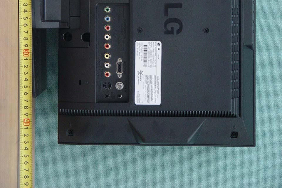
Click to zoom
Application Details
- Equipment Class
- JBP - Part 15 Class B Computing Device Peripheral
- Date of Grant
- Apr 01, 2007
- Application Purpose
- Original Equipment
- Date of Application
- Apr 01, 2007
- Equipment Note
- 15" LCD TV Monitor
- Company
- LG Electronics USA, Inc.
- Country
- United States
Documents & Files
Document Text
Text extracted from the exhibit documents filed with the FCC. Open a document above to read the original.
Users Manual
EUT Type: 15” LCD TV/Monitor FCC ID: BEJ15LS1RG Test Report No.: GETEC-E3-07-024 FCC Class B Certification APPENDIX H : USER’S MANUAL LCD TV Please read this manual carefully before operating your set. Retain it for future reference. Record model number and serial number of the set. See the label attached on the back cover and quote this information to your dealer when you require service. P/NO : 38289U0559J (0703-REV00) Printed in Korea OWNER’S MANUAL MODEL: 15LS1R Internet Home Page : http://www.lgusa.com http://www.lg.ca ENERGYSATR is a set of power-saving guidelines issued by the U.S. Environmental Protection Agency(EPA). As an ENERGY STAR Partner LGE U. S. A.,Inc. has determined that this product meets the ENER- GY STAR guidelines for energy efficiency. 2 Warning WARNING: TO REDUCE THE RISK OF ELECTRIC SHOCK DO NOT REMOVE COVER (OR BACK). NO USER SERVICEABLE PARTS INSIDE. REFER TO QUALIFIED SERVICE PERSONNEL. The lightning flash with arrowhead symbol, within an equilateral triangle, is intended to alert the user to the presence of uninsulated “dangerous voltage” within the product’s enclosure that may be of sufficient magnitude to constitute a risk of electric shock to persons. The exclamation point within an equilateral triangle is intended to alert the user to the presence of important operating and maintenance (servicing) instructions in the literature accompanying the appliance. NOTE TO CABLE/TV INSTALLER: This reminder is provided to call the CATV system installer’s attention to Article 820-40 of the National Electric Code (U.S.A.). The code provides guidelines for proper grounding and, in par- ticular, specifies that the cable ground shall be connected to the grounding system of the build- ing, as close to the point of the cable entry as practical. REGULATORY INFORMATION This equipment has been tested and found to comply with the limits for a Class B digital device, pursuant to Part 15 of the FCC Rules. These limits are designed to provide reasonable pro- tection against harmful interference in a residential installation. This equipment generates, uses and can radiate radio frequency energy and, if not installed and used in accordance with the instructions, may cause harmful interference to radio communications. However, there is no guarantee that interference will not occur in a particular installation. If this equipment does cause harmful interference to radio or television reception, which can be determined by turn- ing the equipment off and on, the user is encouraged to try to correct the interference by one or more of the following measures: - Reorient or relocate the receiving antenna. - Increase the separation between the equipment and receiver. - Connect the equipment into an outlet on a circuit different from that to which the receiver is connected. - Consult the dealer or an experienced radio/TV technician for help. Any changes or modifications not expressly approved by the party responsible for compliance could void the user’s authority to operate the equipment. CAUTION: Do not attempt to modify this product in any way without written authorization from LG Electronics Corporation. Unauthorized modification could void the user’s authority to operate this product. U.S.A. only ----------------------------------------------- COMPLIANCE: The responsible party for this product’s compliance is: LG Electronics U.S.A., Inc. 1000 Sylvan Avenue, Englewood Cliffs, NJ 07632 Phone: 1-800-243-0000 http://us.lge.com --------------------------------------------------------------- CAUTION RISK OF ELECTRIC SHOCK DO NOT OPEN W W arning arning Safety Instructions Safety Instructions 3 Safety Instructions WARNING : To Reduce The Risk Of Fire Or Electric Shock, Do Not Expose This Apparatus To Rain Or Moisture. Apparatus shall not be exposed to dripping or splashing and no objects filled with liquids, such as vases, shall be placed on the apparatus. IMPORTANT SAFETY INSTRUCTIONS 1. Read these instructions. 2. Keep these instructions. 3. Heed all warnings. 4. Follow all instructions. 5. Do not use this apparatus near water. 6. Clean only with a dry cloth. 7. Do not block any of the ventilation open- ings. Install in accordance with the manu- facturer’s instructions. 8. Do not install near any heat sources such as radiators, heat registers, stoves, or other apparatus (including amplifiers) that pro- duce heat. 9. Do not defeat the safety purpose of the polarized or grounding type plug. A polar- ized plug has two blades with one wider than the other. A grounding type plug has two blades and a third grounding prong. The wide blade or the third prong is provided for your safety. When the provided plug does not fit into your outlet, consult an electrician for replacement of the obsolete outlet. 10. Protect the power cord from being walked on or pinched particularly at plugs, conve- nience receptacles, and the point where they exit from the apparatus. 11. Only use the attachments / accessories specified by the manufacturer. O w n e r's M a n u a l 4 Safety Instructions Safety Instructions continued Safety Instructions continued 12. Use only with a cart, stand, tripod, bracket, or table specified by the manufacturer, or sold with the apparatus. When a cart is used, use caution when moving the cart / apparatus combination to avoid injury from tip-over. 13. Unplug this apparatus during lightning storms or when unused for long periods of time. 14. Refer all servicing to qualified service per- sonnel. Servicing is required when the apparatus has been damaged in any way, such as power supply cord or plug is dam- aged, liquid has been spilled or objects have fallen into the apparatus, the appara- tus has been exposed to rain or moisture, does not operate normally, or has been dropped. On Disposal a. The fluorescent lamp used in this product contains a small amount of mercury. b. Do not dispose of this product with general household waste. Disposal of this product must be carried out in accordance to the…
Text truncated - open the document above for the full version.
Users Manual
22 Operation 1. Press the MTSbutton repeatedly. Stereo/SAP Stereo/SAP Broadcasts Setup Broadcasts Setup •Select mono sound mode if the signal is not clear or in poor signal reception areas. •Stereo, SAPmode are available only if included on the broadcast signal. MonoStereoSAP - The TV can receive MTS stereo programs and any SAP (Secondary Audio Program) that accompanies the stereo program, if the broadcaster transmits an additional sound signal as well as the original one. - Mono: The primary language is heard from left and right speakers. Signal mode is mono. - Stereo: The primary language is heard from left and right speakers. Signal mode is stereo. - SAP: The secondary language is heard from left and right speakers. Sound Menu Options continued Sound Menu Options continued 1.Press the MENUbutton and then use DD / EE button to select the SOUNDmenu. 2. Press the GG button and then use DD / EE button to select Balance. 3. Press the GG button and then use FF / GG button to adjust the sound balance. • Balance is adjustable from Left 50 to Right 50. 4. Press the ENTERbutton to save. Sound Balance Sound Balance SOUND EZ Audio AVL Balance 0 FG ÁMENU D E 23 Operation T T imer Menu Options imer Menu Options Auto Clock Setup Auto Clock Setup - If the time on the clock is incorrect, reset the clock manually. 1. Press the MENUbutton and then use DD / EE button to select the TIMERmenu. 2. Press the GG button and then use DD / EE button to select Clock. 3. Press the GG button and then use DD / EE button to select Auto. 4. Press the GG button and then use DD / EE button to select the time zone for your viewing area. Your choices are: Auto, E.S.T. (Eastern Standard Time), C.S.T. (Central Standard Time), M.S.T. (Mountain Standard Time), P.S.T. (Pacific Standard Time), Alaska, and Hawaii. 5. Press the GG button and then use DD / EE button to set PBS channel. 6. Press the GG button and then use DD / EE button to set D.S.T.(Daylight Savings Time)Auto, Offor On, depending on whether or not your viewing area observes Daylight Savings Time. 7. Press the ENTERbutton to save. - The time is set automatically through from a PBS broadcast signal. - The PBS channel signal includes information for the correct time and daylight saving time. Manual Clock Setup Manual Clock Setup 1. Press the MENUbutton and then use DD / EE button to select the TIMERmenu. 2. Press the GG button and then use DD / EE button to select Clock. 3. Press the GG button and then use DD / EE button to select Manual. 4. Press the GG button and then use DD / EE button to set the hour. 5. Press the GG button and then use DD / EE button to set the minutes. 6. Press the ENTERbutton to save. TIMER Auto G Manual - - : - - AM Clock Off timer On timer Auto off TIMER Auto Manual - - : - - AM Clock Off timer On timer Auto off Auto clock Time zone Auto PBS CH. TV 1 D.S.T. Auto FG ÁMENU D E FG ÁMENU D E F ÁMENU D E 24 Operation - Timer function operates only if current time is set. - Off-Timer function overrides On-Timer function if they are set to the same time. - The TV must be in standby mode for the On-Timer to work. - If you don’t press any button within 2 hours after turning on the TV with the On-Timer function, the TV will automatically revert to standby mode. On/Of On/Of f f T T imer Setup imer Setup 1. Press the MENUbutton and then use DD / EE button to select the TIMERmenu. 2. Press the GG button and then use DD / EE button to select Off timer or On timer. 3. Press the GG button and then use DD / EE button to set the hour. 4. Press the GG button and then use DD / EE button to set the minutes. 5.ForOn timerfunction only: Press the GG button and then use DD / EE button to set the chan- nel at turn-on.Then, press the GG button and then use DD / EE button to set the turn-on sound level. 6. Press the GG button and then use DD / EE button to select Onor Off. • Off: Off timer/On timerwill not work. On: Off timer/On timerare active. 7. Press the ENTERbutton to save. Sleep Sleep T T imer Setup imer Setup - The Sleep Timer turns the TV off at a preset time. 1. Press the SLEEPbutton repeatedly to select the number of minutes. First the ‘ --- Min.’option appears on the screen, followed by the following sleep timer options: 10, 20, 30, 60, 90, 120, 180, and 240 minutes. 2. When the number of minutes you want is displayed on the screen, press the ENTERbutton. The timer begins to count down from the number of minutes selected. 3. To check the remaining minutes before the TV turns off, press the SLEEPbutton once. 4. To cancel the Sleep Timer, press the SLEEPbutton repeatedly until ‘ --- Min.’appears. Auto of Auto of f f - If Auto off is active and there is no input signal, the TV switches to Standby mode automatically after 10 minutes. 1. Press the menubutton and then use DD / EE button to select the TIMERmenu. 2. Press the GG button and then use DD / EE button to select Auto off. 3. Press the GG button and then use DD / EE button to select On or Off. 4. Press the ENTERbutton to save. TIMER Clock Off timer On timer Auto off On Off T T imer Menu Options continued imer Menu Options continued TIMER Clock Off timer On timer Auto off - -: - - AM TV2 Volume30 On FG ÁMENU D E F ÁMENU D E 25 Operation Special Menu Options Special Menu Options Closed Captions Closed Captions 2. An old, bad, or illegally recorded tape is being played. 3. Strong, random signals from a car or airplane interfere with the TV signal. 4. The signal from the antenna is weak. 5. The program wasn’t captioned when it was produced, transmitted, or taped. Closed captioning is a process which converts the audio portion of a television program into written words which then appear as subtitles on the television screen. Closed captions allow viewers to read the dia- logue and narration of television programs. Captions are the subtitles of the dialogue and narration of television programs. For prerecorded programs, program dialogue can be arranged into captions in advance. Its possible to caption a live pr…
Text truncated - open the document above for the full version.
Block Diagram
EUT Type: 15” LCD TV/Monitor FCC ID: BEJ15LS1RG Test Report No.: GETEC-E3-07-024 FCC Class B Certification APPENDIX D : BLOCK DIAGRAM Block diagram(회로) X-tal X301: 24.576 Mhz 65 Mhz DESCRIPTION OF BLOCK DIAGRAM
External Photos
EUT Type: 15” LCD TV/Monitor FCC ID: BEJ15LS1RG Test Report No.: GETEC-E3-07-024 FCC Class B Certification APPENDIX F : EXTERNAL PHOTOGRAPHS EUT Type: 15” LCD TV/Monitor FCC ID: BEJ15LS1RG Test Report No.: GETEC-E3-07-024 FCC Class B Certification EUT Type: 15” LCD TV/Monitor FCC ID: BEJ15LS1RG Test Report No.: GETEC-E3-07-024 FCC Class B Certification EUT Type: 15” LCD TV/Monitor FCC ID: BEJ15LS1RG Test Report No.: GETEC-E3-07-024 FCC Class B Certification EUT Type: 15” LCD TV/Monitor FCC ID: BEJ15LS1RG Test Report No.: GETEC-E3-07-024 FCC Class B Certification EUT Type: 15” LCD TV/Monitor FCC ID: BEJ15LS1RG Test Report No.: GETEC-E3-07-024 FCC Class B Certification EUT Type: 15” LCD TV/Monitor FCC ID: BEJ15LS1RG Test Report No.: GETEC-E3-07-024 FCC Class B Certification
ID Label/Location Info
EUT Type: 15” LCD TV/Monitor FCC ID: BEJ15LS1RG Test Report No.: GETEC-E3-07-024 FCC Class B Certification APPENDIX C : ID SAMPLE LABEL & LOCATION EUT Type: 15” LCD TV/Monitor FCC ID: BEJ15LS1RG Test Report No.: GETEC-E3-07-024 FCC Class B Certification LABELLING REQUIREMENTS The label shown shall be permanently affixed at a conspicuous location on the device and be readily visible to the user at the time of purchase. ID Label ID Label Location of EUT ID Label
Internal Photos
EUT Type: 15” LCD TV/Monitor FCC ID: BEJ15LS1RG Test Report No.: GETEC-E3-07-024 FCC Class B Certification APPENDIX G : INTERNAL PHOTOGRAPHS EUT Type: 15” LCD TV/Monitor FCC ID: BEJ15LS1RG Test Report No.: GETEC-E3-07-024 FCC Class B Certification EUT Type: 15” LCD TV/Monitor FCC ID: BEJ15LS1RG Test Report No.: GETEC-E3-07-024 FCC Class B Certification EUT Type: 15” LCD TV/Monitor FCC ID: BEJ15LS1RG Test Report No.: GETEC-E3-07-024 FCC Class B Certification EUT Type: 15” LCD TV/Monitor FCC ID: BEJ15LS1RG Test Report No.: GETEC-E3-07-024 FCC Class B Certification EUT Type: 15” LCD TV/Monitor FCC ID: BEJ15LS1RG Test Report No.: GETEC-E3-07-024 FCC Class B Certification EUT Type: 15” LCD TV/Monitor FCC ID: BEJ15LS1RG Test Report No.: GETEC-E3-07-024 FCC Class B Certification EUT Type: 15” LCD TV/Monitor FCC ID: BEJ15LS1RG Test Report No.: GETEC-E3-07-024 FCC Class B Certification EUT Type: 15” LCD TV/Monitor FCC ID: BEJ15LS1RG Test Report No.: GETEC-E3-07-024 FCC Class B Certification EUT Type: 15” LCD TV/Monitor FCC ID: BEJ15LS1RG Test Report No.: GETEC-E3-07-024 FCC Class B Certification EUT Type: 15” LCD TV/Monitor FCC ID: BEJ15LS1RG Test Report No.: GETEC-E3-07-024 FCC Class B Certification EUT Type: 15” LCD TV/Monitor FCC ID: BEJ15LS1RG Test Report No.: GETEC-E3-07-024 FCC Class B Certification EUT Type: 15” LCD TV/Monitor FCC ID: BEJ15LS1RG Test Report No.: GETEC-E3-07-024 FCC Class B Certification EUT Type: 15” LCD TV/Monitor FCC ID: BEJ15LS1RG Test Report No.: GETEC-E3-07-024 FCC Class B Certification EUT Type: 15” LCD TV/Monitor FCC ID: BEJ15LS1RG Test Report No.: GETEC-E3-07-024 FCC Class B Certification EUT Type: 15” LCD TV/Monitor FCC ID: BEJ15LS1RG Test Report No.: GETEC-E3-07-024 FCC Class B Certification EUT Type: 15” LCD TV/Monitor FCC ID: BEJ15LS1RG Test Report No.: GETEC-E3-07-024 FCC Class B Certification
Test Report
EUT Type: 15” LCD TV/Monitor FCC ID: BEJ15LS1RG Page 2 of 21 Test Report No.: GETEC-E3-07-024 FCC Class B Certification CONTENTS 1. GENERAL INFORMATION ......................................................................................................................................3 2. INTRODUCTION ........................................................................................................................................................4 3. PRODUCT INFORMATION ......................................................................................................................................5 3.1 DESCRIPTION OF EUT..............................................................................................................................................5 3.2 SUPPORT EQUIPMENT / CABLES USED.....................................................................................................................6 3.3 MODIFICATION ITEM(S) ...........................................................................................................................................7 4. DESCRIPTION OF TESTS.........................................................................................................................................8 4.1 TEST CONDITION......................................................................................................................................................8 4.2 CONDUCTED EMISSION............................................................................................................................................9 4.3 RADIATED EMISSION..............................................................................................................................................10 5. CONDUCTED EMISSION........................................................................................................................................ 11 5.1 OPERATING ENVIRONMENT................................................................................................................................... 11 5.2 TEST SET-UP............................................................................................................................................................ 11 5.3 MEASUREMENT UNCERTAINTY.............................................................................................................................. 11 5.4 LIMIT......................................................................................................................................................................12 5.5 TEST EQUIPMENT USED..........................................................................................................................................12 5.6 TEST DATA FOR POWER LINE CONDUCTED EMISSION............................................................................................13 6. RADIATED EMISSION ............................................................................................................................................16 6.1 OPERATING ENVIRONMENT...................................................................................................................................16 6.2 TEST SET-UP............................................................................................................................................................16 6.3 MEASUREMENT UNCERTAINTY..............................................................................................................................16 6.4 LIMIT......................................................................................................................................................................17 6.5 TEST EQUIPMENT USED..........................................................................................................................................17 6.6 TEST DATA FOR RADIATED EMISSION.....................................................................................................................18 7. SAMPLE CALCULATIONS.....................................................................................................................................20 7.1 EXAMPLE 1 : ...........................................................................................................................................................20 7.2 EXAMPLE 2 : ...........................................................................................................................................................20 8. RECOMMENDATION & CONCLUSION..............................................................................................................21 APPENDIX A – ATTESTATION STATEMENT APPENDIX B – PLOTS OF CONDUCTED EMISSIONS APPENDIX C – ID SAMPLE LABEL & LOCATION APPENDIX D – BLOCK DIAGRAM APPENDIX E – TEST SET-UP PHOTOGRAPHS APPENDIX F – EXTERNAL PHOTOGRAPHS APPENDIX G –INTERNAL PHOTOGRAPHS APPENDIX H – USER’S MANUAL EUT Type: 15” LCD TV/Monitor FCC ID: BEJ15LS1RG Page 3 of 21 Test Report No.: GETEC-E3-07-024 FCC Class B Certification Scope: Measurement and determination of electromagnetic emissions (EME) of radio frequency devices including intentional and / or unintentional radiators for compliance with technical rules and regulations of the Federal Communications Commission. 1. General Information z FCC ID BEJ15LS1RG z EUT Type 15” LCD TV/Monitor z Model No. 15LS1R-MG z Tra de Na me LG z Serial No. Proto type z Rule Part(s) FCC Part 15 Subpart B z Type of Authority Certification z Test Procedure(s) ANSI C63.4 (2003) / Canadian standard ICES-003 z Dates of Test March 28, 2007 z Place of Test Gumi College EMC Center ( FCC Registration No.: 100749) 407, Bugok-Dong, Gumi-si, Gyeongsangbuk-Do, Korea z Test Report No. GETEC-E3-07-024 z Dates of Issue April 2, 2007 Applicant: LG Electronics Inc. Applicant Address: 642, Jinpyung-Dong, Gumi-Si, Gyeongsangbuk-do, Korea Manufacturer: LG Electronics Inc. Manufacturer Address: 642,…
Text truncated - open the document above for the full version.
Test Report
EUT Type: 15” LCD TV/ Monitor FCC ID: BEJ15LS1RG Test Report No.: GETEC-E3-07-024 FCC Class B Certification APPENDIX B : PLOTS OF CONDUCTED EMISSIONS EUT Type: 15” LCD TV/ Monitor FCC ID: BEJ15LS1RG Test Report No.: GETEC-E3-07-024 FCC Class B Certification Test Mode:1024 *768 / 60Hz (Analog) < Hot line > < Neutral line > EUT Type: 15” LCD TV/ Monitor FCC ID: BEJ15LS1RG Test Report No.: GETEC-E3-07-024 FCC Class B Certification Test Mode:800*600 / 75Hz (Analog) < Hot line > < Neutral line > EUT Type: 15” LCD TV/ Monitor FCC ID: BEJ15LS1RG Test Report No.: GETEC-E3-07-024 FCC Class B Certification Test Mode:640*480 / 60Hz (Analog) < Hot line > < Neutral line >
Test Setup Photos
EUT Type: 15” LCD TV/Monitor FCC ID: BEJ15LS1RG Test Report No.: GETEC-E3-07-024 FCC Class B Certification APPENDIX E : TEST SET UP PHOTOGRAPHS EUT Type: 15” LCD TV/Monitor FCC ID: BEJ15LS1RG Test Report No.: GETEC-E3-07-024 FCC Class B Certification The Conducted Test Picture and Radiated Test Picture show the worst-case configuration and cable placement. Conducted Test Picture (Front) Conducted Test Picture (Rear) EUT Type: 15” LCD TV/Monitor FCC ID: BEJ15LS1RG Test Report No.: GETEC-E3-07-024 FCC Class B Certification Radiated Test Picture (Front) Radiated Test Picture (Rear)
Contact Information
Applicant
David Kim(Team leader, LGEUS NA Policy & Regulatory Affairs)
Test Firm
GUMI UNIVERSITY EMC CENTERTea-Sig Park
Technical Specifications
| # | Rule Parts | Frequency Range | Power Output |
|---|---|---|---|
| 1 | 15B | - | - |
Other Applications from LG Electronics USA, Inc.

BEJTFHOBINI1F1
Jan 08, 2025Telematics
Equipment Class
DTS - Digital Transmission SystemBEJNT-16Z90TS
Oct 02, 2024Notebook Computer
Equipment Class
DSS - Part 15 Spread Spectrum TransmitterBEJSP-PEW8
Sep 26, 2024Stylus Pen
Equipment Class
DCD - Part 15 Low Power Transmitter Below 1705 kHzBEJ-RSMV2
Sep 24, 2024RF Module
Equipment Class
FDS - Part 15 Field Disturbance SensorBEJTFBMEIBN3EU
Sep 24, 2024Telematics
Equipment Class
NII - Unlicensed National Information Infrastructure TX