BEJ3G1XINBTSSTAREX-IS 1900 Indoor BTS
LG Electronics USA, Inc.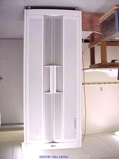
Click to zoom
Application Details
- Equipment Class
- PCB - PCS Licensed Transmitter
- Date of Grant
- Nov 04, 2001
- Application Purpose
- Original Equipment
- Date of Application
- Nov 04, 2001
- Equipment Note
- STAREX-IS 1900 Indoor BTS
- Frequency Range
- 1931.25000000 - 1988.75000000
- Company
- LG Electronics USA, Inc.
- Country
- United States
Documents & Files
Document Text
Text extracted from the exhibit documents filed with the FCC. Open a document above to read the original.
Users Manual
STAREX-BSS IS2000 BSM User’s Manual ( STAREX-IS User’s Manual ) STAREX-IS BSM Manual Page:1(877) Issue:1. 0 SMD-011-PMA210 This equipment has been tested and found to comply with the limits for a Class A digital device, pursuant to part 15 of the FCC Rules. These limits are designated to provide reasonable protection against harmful interference when the equipment is operated in a commercial environment. This equipment generates, uses, and can radiate radio frequency energy and, if not installed and used in accordance with the instruction manual, may cause harmful interference to radio communications. Operation of this equipment in a residential area is likely to cause harmful interference in which case the user will be required to correct the interference at his own expense. CAUTION : Do not attempt to modify this product in any way without written authorization from LG Electronics Inc. Unauthorized modification could void the user's authority to operate this product. The responsible party for this device compliance is : Company Name : LGInfoComm U.S.A. Inc. Address : 10225 Willow Creek RD San Diego, CA, 92131, U.S.A. Telephone No. : 858-635-5332 STAREX-IS BSM Manual Page:2(877) Issue:1. 0 SMD-011-PMA210 Contents 1. Introduction to BSM................................................................................................. 36 1.1. Overview........................................................................................................... 36 1.1.1. Configuration Management of System.....................................................................36 1.1.2. Fault Management of System...................................................................................36 1.1.3. Performance Management of System......................................................................38 1.1.4. Security Management of System.............................................................................39 1.1.5. Account Management of System .............................................................................39 1.2. Interoperability and Operation.......................................................................... 39 1.2.1. Configuration Management of System.....................................................................40 1.2.2. Fault Management of System...................................................................................40 1.2.3. Performance Management of System......................................................................40 1.2.4. Security Management of System.............................................................................41 1.2.5. Account Management of System .............................................................................42 1.3. BSM Configuration............................................................................................ 42 1.3.1. S/W System Boundary..............................................................................................42 1.3.2. S/W Architecture......................................................................................................43 2. BSM Environment Setting........................................................................................ 45 2.1. OS Installation................................................................................................... 45 2.1.1. Solaris 2.7 Installation Procedures..........................................................................45 2.1.2. Network Environment Setting Procedures..............................................................63 2.2. DBMS(Informix) Installation.............................................................................. 66 2.2.1. Informix Install.........................................................................................................66 2.2.2. Environment Setting.................................................................................................75 2.2.3. Execution..................................................................................................................81 2.2.4. Others.......................................................................................................................82 2.3. ATM Adaptor Setup.......................................................................................... 85 2.3.1. SunATM Adopter Setup.........................................................................................85 2.3.2. SunATM S/W Installation and Solaris Setup File Modification...............................85 2.3.3. SunATM IPoA Driver Load......................................................................................91 2.3.4. System File Changed by atm_setup Tool................................................................92 2.4. User Environment........................................................................................... 129 3. BSM Package Configuration................................................................................... 129 3.1. Application Configuration................................................................................ 129 4. BSM Command....................................................................................................... 132 4.1. User Interface Command................................................................................ 132 STAREX-IS BSM Manual Page:3(877) Issue:1. 0 SMD-011-PMA210 4.1.1. User Management Command .................................................................................132 4.1.2. Command Management Command.........................................................................139 4.1.3. History Management Command.............................................................................143 4.2. Loading Command........................................................................................... 148 4.2.1. Loading Control Command....................................................................................…
Text truncated - open the document above for the full version.
Users Manual
STAREX-IS BSM Manual Page:199(877) Issue:1. 0 SMD-011-PMA210 Fig. 4.3-27 Forward Link Power Management Information (RS2) Verification STAREX-IS BSM Manual Page:200(877) Issue:1. 0 SMD-011-PMA210 4.3.2.6. Backward Link Power Management Information (RS2) Verification Rate Set 2 transmits data at the speed of 14400,7200,3600,1800 bps. Input the following command to check the parameter information for RS2 Backward Link Power Management. Among the input values, FER (Frame Error Rate) has the value ranging from 0.5%, 1 to 5%. • Command DIS-RS2-REVP: BSC=a, BTS=b, FER=c; a : BSC Number(0~11) b: BTS Number(0~47) c:FER (POINT_5/PERCENT_1/PERCENT_2/PERCENT_3/PERCENT_4/PERCET_5) • Input DIS-RS2-REVP: BSC=0, BTS=0, FER=POINT_5; • Output STAREX-IS BSM Manual Page:201(877) Issue:1. 0 SMD-011-PMA210 Fig. 4.3-28 Backward Link Power Management Information (RS2) Verification STAREX-IS BSM Manual Page:202(877) Issue:1. 0 SMD-011-PMA210 4.3.2.7. Service Option FER Verification Target FER can be designated by the Service Option. Input the following command to display this information. In the next display, 1% Target FER is applied for the "8K VOICE" Service Option and for this, the following power management information is used: RS1 forward link power management information, RS1 backward link power management information, RS2 forward link power management information, and RS2 backward (or reverse-direction) link power management information. • Command DIS-FER-PARA: BSC=a; a : BSC Number(0~11) • Input DIS-FER-PARA: BSC=0; • Output STAREX-IS BSM Manual Page:203(877) Issue:1. 0 SMD-011-PMA210 Fig. 4.3-29 Service Option FER Verification STAREX-IS BSM Manual Page:204(877) Issue:1. 0 SMD-011-PMA210 4.3.2.8. MAHHO Verification • Command DIS-MAHH-PARA: BSC=a, BTS=b, SECT=c; a : BSC Number(0~11) b: BTS Number(0~47) c: Sector Id .(ALPHA/BETA/GAMMA) • Input DIS-MAHH-PARA: BSC=0,BTS=0,SECT=ALPHA; • Output Fig. 4.3-30 MAHHO Verification STAREX-IS BSM Manual Page:205(877) Issue:1. 0 SMD-011-PMA210 4.3.2.9. LOCATION Verification • Command DIS-LOC-PARA: BSC=a, BTS=b, SECT=c; a : BSC Number(0~11) b: BTS Number(0~47) c: Sector Id .(ALPHA/BETA/GAMMA) • Input DIS-LOC-PARA: BSC=0,BTS=0,SECT=ALPHA; • Output Fig. 4.3-31 LOCATION Verification STAREX-IS BSM Manual Page:206(877) Issue:1. 0 SMD-011-PMA210 4.3.2.10. SCH Verification • Command DIS-SCH-PARA: BSC=a, BTS=b, SECT=c; a : BSC Number(0~11) b: BTS Number(0~47) c: Sector Id .(ALPHA/BETA/GAMMA) • Input DIS-SCH-PARA: BSC=0,BTS=0,SECT=ALPHA; • Output Fig. 4.3-32 SCH Verification STAREX-IS BSM Manual Page:207(877) Issue:1. 0 SMD-011-PMA210 4.3.2.11. Power Control Data Verification • Command DIS-PWR-CTRL: BSC=a, BTS=b, FER=c; a : BSC Number(0~11) b: BTS Number(0~47) c: FER (0~30) • Input DIS-PWR-CTRL: BSC=0, BTS=0,FER=0; • Output STAREX-IS BSM Manual Page:208(877) Issue:1. 0 SMD-011-PMA210 Fig. 4.3-33 Power Control Data Verification STAREX-IS BSM Manual Page:209(877) Issue:1. 0 SMD-011-PMA210 4.3.2.12. BTS Name Display Input the following command to display the BTS name: • Command DIS-BTS-NAME: BSC=a, BTS=b; a : BSC Number(0~11) b: BTS Number(0~47) • Input DIS-BTS-NAME: BSC=0, BTS=0; • Output Fig. 4.3-34 BTS Name Display STAREX-IS BSM Manual Page:210(877) Issue:1. 0 SMD-011-PMA210 4.3.2.13. PCP Timer Information Verification • Command DIS-PCF-TIMER:PCP =a; a : PCP Number(0~2) • Input DIS-PCF-TIMER: PCP=0; • Output Fig. 4.3-35 PCP Timer Information Verification STAREX-IS BSM Manual Page:211(877) Issue:1. 0 SMD-011-PMA210 4.3.2.14. PCF Parameter Information Verification • Command DIS-PCF-PARA :PCP =a; a : PCP Number(0~2) • Input DIS-PCF-PARA: PCP=0; • Output Fig. 4.3-36 PCF Parameter Information Verification STAREX-IS BSM Manual Page:212(877) Issue:1. 0 SMD-011-PMA210 4.3.2.15. PCF MAC ADDRESS Information Verification • Command DIS-PCF-MAC :PCP =a; a : PCP Number(0~2) • Input DIS-PCF-MAC: PCP=0; • Output Fig. 4.3-37 PCF MAC ADDRESS Information Verification STAREX-IS BSM Manual Page:213(877) Issue:1. 0 SMD-011-PMA210 4.3.3. NETWORK Information Display (Display_Parameter_Information_3) 4.3.3.1. CAN ATM NODE Information Display • Command DIS-CAN-NODE; • Output STAREX-IS BSM Manual Page:214(877) Issue:1. 0 SMD-011-PMA210 Fig. 4.3-38 CAN ATM NODE Information Display STAREX-IS BSM Manual Page:215(877) Issue:1. 0 SMD-011-PMA210 4.3.3.2. CAN PVC SETTING Information Display • Command DIS-CAN-PVC;NODE_A=a; • Input DIS-CAN-PVC: NODE_A=BSM_A; a: BSM_A,BSM_B, BSC (0~11) • Output Fig. 4.3-39 CAN PVC SETTING Information Display STAREX-IS BSM Manual Page:216(877) Issue:1. 0 SMD-011-PMA210 4.3.3.3. CAN NETWORK PARAMETER Information Display • Command DIS-CAN-NETP; • Input DIS-CAN-NETP; • Output Fig. 4.3-40 CAN NETWORK PARAMETER Information Display STAREX-IS BSM Manual Page:217(877) Issue:1. 0 SMD-011-PMA210 4.3.3.4. CAN INTER BSC AAL2 Setting Information Display • Command DIS-CAN-IUR:BSC=a; a:BSC Number (0~11) • Input DIS-CAN-IUR:BSC=0; • Output Fig. 4.3-41 CAN INTER BSC AAL2 Setting Information Display STAREX-IS BSM Manual Page:218(877) Issue:1. 0 SMD-011-PMA210 4.3.3.5. CAN INTER BSC AAL5 Setting Information Display • Command DIS-CAN-BSC; • Output Fig. 4.3-42 CAN INTER BSC AAL5 Setting Information Display STAREX-IS BSM Manual Page:219(877) Issue:1. 0 SMD-011-PMA210 4.3.3.6. CAN ATM NODE Information Display • Command DIS-CPN-NODE; • Output Fig. 4.3-43 CAN ATM NODE Information Display STAREX-IS BSM Manual Page:220(877) Issue:1. 0 SMD-011-PMA210 4.3.3.7. PCF ATM NODE Information Display • Command DIS-PCF-NODE • Output Fig. 4.3-44 PCF ATM NODE Information Display STAREX-IS BSM Manual Page:221(877) Issue:1. 0 SMD-011-PMA210 4.3.3.8. CAN PVC SETTING Information Display • Command DIS-CPN-PVC • Output Fig. 4.3-45 CAN PVC SETTING Information Display STAREX-IS BSM Manual Page:222(877) Issue:1. 0 SMD-011-PMA210 4.3.3.9. CAN PCF PVC SETTING Information Display • Command DIS-PCF-PVC • Output Fig. 4.3-46 CAN PCF PVC SETTING Information Display STAREX-IS BSM Manual Page:223(877) Issue:1. 0 SMD-011-PMA210 4.3.3.10. CP…
Text truncated - open the document above for the full version.
Users Manual
STAREX-IS BSM Manual Page:399(877) Issue:1. 0 SMD-011-PMA210 Fig. 4.4-24 Result of SLPA BLOCK Command 4.4.4.8. SLPA UNBLOCK Command Function to unblock SLPA. Command : UBLK-SLPA:BSC=a,SMP=b,SLPA=c,[SLV=d]; a : BSC Number(00~11) b : SMP Number(00~04) c : SLPA Number(00~17) d : SLV Number(00~03) Input : UBLK-SLPA:BSC=0,SMP=0,SLPA=0,SLV=0; Fig. 4.4-25 Result of SLPA UNBLOCK Command 4.4.4.9. VCPA BLOCK Command Function to block VCPA. Command : BLK-VCPA:BSC=a,VMP=b,VCPA=c,[SLV=d],[DSP=e]; a : BSC Number(00~11) STAREX-IS BSM Manual Page:400(877) Issue:1. 0 SMD-011-PMA210 b : VMP Number(00~07) c : VCPA Number(00~15) d : SLV Number(00~01) e : DSP Number(00~03) Input : BLK-VCPA:BSC=0,VMP=0,VCPA=0,SLV=0,DSP=0; Fig. 4.4-26 Result of VCPA BLOCK Command 4.4.4.10. VCPA UNBLOCK Command Function to unblock VCPA Command : UBLK-VCPA:BSC=a,VMP=b,VCPA=c,[SLV=d],[DSP=e]; a : BSC Number(00~11) b : VMP Number(00~07) c : VCPA Number(00~15) d : SLV Number(00~01) e : DSP Number(00~03) Input : UBLK-VCPA:BSC=0,VMP=0,VCPA=0,SLV=0,DSP=0; STAREX-IS BSM Manual Page:401(877) Issue:1. 0 SMD-011-PMA210 Fig. 4.4-27 Result of VCPA UNBLOCK Command 4.4.4.11. VLIA BLOCK Command Function to block VLIA. Command : BLK-VLIA:BSC=0,VMP=0,VLIA=0,[E1=0],[TS=1]; a : BSC Number(00~11) b : VMP Number(00~07) c : VLIA Number(0~1) d : E1 Number(00~15) e : TS Number(00~31) Input : BLK-VLIA:BSC=0,VMP=0,VLIA=0,E1=0,TS=1; Fig. 4.4-28 Result of VLIA BLOCK Command 4.4.4.12. VLIA UNBLOCK Command Function to unblock VLIA Command : UBLK-VLIA:BSC=0,VMP=0,VLIA=0,[E1=0],[TS=1]; a : BSC Number(00~11) b : VMP Number(00~07) STAREX-IS BSM Manual Page:402(877) Issue:1. 0 SMD-011-PMA210 c : VLIA Number(0~1) d : E1 Number(00~15) e : TS Number(00~31) Input : UBLK-VLIA:BSC=0,VMP=0,VLIA=0,E1=0,TS=1; Fig. 4.4-29 Result of VLIA UNBLOCK Command 4.4.4.13. H/W RESET BSC Device Command Function to reset BSC Device on H/W Level. Command : RMT-BSC-DEV:BSC=a,PROC=b,DEV=c,ID=d,[SUBID=e],CLS=f; a : BSC Number(00~11) b : Processor Name(NCP,SCP,ALP,SMP(00~05),VMP(00~07)) c : Device Name(SLPA,VCPA,VLIA,STIA,ASCA,ASIA,AOTA,ATSA,ALMA) d : Device ID(00~17) e : Sub_id(A_SIDE,B_SIDE) f : Class(HARDRST,ISOLAT,UNISOL) Input : RMT-BSC-DEV:BSC=0,PROC=SMP00,DEV=SLPA,ID=0,CLS=HARDRST; STAREX-IS BSM Manual Page:403(877) Issue:1. 0 SMD-011-PMA210 Fig. 4.4-30 Result of BSC Device H/W Reset Command 4.4.4.14. H/W RESET ALPA Command Function to reset ALPA on H/W Level. Command : RMT-ALPA:BSC=0,ALMA=0,ALPA=0,CLS=HARDRST; a : BSC Number(00~11) b : ALMA ID(0~1) c : ALPA ID(0~4) d : Class(HARDRST,ISOLAT,UNISOL) Input : RMT-ALPA:BSC=0,ALMA=0,ALPA=0,CLS=HARDRST; Fig. 4.4-31 Result of H/W RESET ALPA Command 4.4.5. Bts Device Status Control 4.4.5.1. BTS Device Status Display Command Function to display the BTS Device status Command : DIS-BTS-DEV:BSC=a,BTS=b,PROC=c; a : BSC Number(00~11) b : BTS Number(00~47) c : Processor Name(BSP,BPP,CRP,RCP(00~06) STAREX-IS BSM Manual Page:404(877) Issue:1. 0 SMD-011-PMA210 Input : DIS-BTS-DEV:BSC=0,BTS=0,PROC=CRP; Fig. 4.4-32 Result of BTS Device Status Display Command 4.4.5.2. FA Status Display Command Function to display FA Status. Command : DIS-FA-STS:BSC=a,BTS=bFA=c; a : BSC Number(00~11) b : BTS Number(00~47) c : FA Number(0~7) Input : DIS-FA-STS:BSC=0,BTS=0,FA=0; STAREX-IS BSM Manual Page:405(877) Issue:1. 0 SMD-011-PMA210 Fig. 4.4-33 Result of FA Status Display Command 4.4.5.3. BLOCK DBPA Command Function to block DBPA. Command : BLK-DBPA:BSC=a,BTS=b,RCP=c,DBPA=d,[CHIP=e],[CONDITION=f]; a : BSC Number(00~11) b : BTS Number(00~47) c : RCP Number(0~5) STAREX-IS BSM Manual Page:406(877) Issue:1. 0 SMD-011-PMA210 d : DBPA Number(0~9) e : CHIP Number(0~1) f : Select Option(conditional, unconditional) Conditional : If there is call connected, wait until it is disconnected during timeout and then block it. If it is not disconnected until timeout, do not block it. Unconditional : block a call regardless of their presence unconditionally. (The existing call is disconnected) Reference : If an OverHead Channel is allocated, do not block a call unconditionally. Input : BLK-DBPA:BSC=0,BTS=0,RCP=0,DBPA=1,CHIP=1,CONDITION=CONDITION; Fig. 4.4-34 Result of BLOCK DBPA Command 4.4.5.4. UNBLOCK DBPA Command Function to unblock DBPA Command : UBLK-DBPA:BSC=a,BTS=b,RCP=c,DBPA=d,[CHIP=e],[CONDITION=f]; a : BSC Number(00~11) b : BTS Number(00~47) c : RCP Number(0~5) d : DBPA Number(0~9) e : CHIP Number(0~1) Input : UBLK-DBPA:BSC=0,BTS=0,RCP=0,DBPA=1,CHIP=1; STAREX-IS BSM Manual Page:407(877) Issue:1. 0 SMD-011-PMA210 Fig. 4.4-35 Result of UNBLOCK DBPA Command 4.4.5.5. BLOCK OverHead Channel Element Display Command Function to block OverHead Channel Element Command : BLK-OVHD-CE:BSC=a,BTS=b,SECTOR=c,FA=d; a : BSC Number(00~11) b : BTS Number(00~47) c : SECTOR(ALPHA,BETA,GAMMA,DELTA,EPSILON,ZETA) d : FA Number(0~5) Input : BLK-OVHD-CE:BSC=0,BTS=0,SECTOR=ALPHA,FA=0; Fig. 4.4-36 Result of BLOCK OverHead Channel Element Display 4.4.5.6. UNBLOCK OverHead Channel Element Function to unblock OverHead Channel Element STAREX-IS BSM Manual Page:408(877) Issue:1. 0 SMD-011-PMA210 Command : UBLK-OVHD-CE:BSC=a,BTS=b,SECTOR=c,FA=d; a : BSC Number(00~11) b : BTS Number(00~47) c : SECTOR(ALPHA,BETA,GAMMA,DELTA,EPSILON,ZETA) d : FA Number(0~5) Input : UBLK-OVHD-CE:BSC=0,BTS=0,SECTOR=ALPHA,FA=0; Fig. 4.4-37 Result of UNBLOCK OverHead Channel Element 4.4.5.7. H/W RESET BTS Device Command Function to reset BTS Device on H/W.Level Command : RMT-BTS-DEV:BSC=a,BTS=b,PROC=c,DEV=d,[ID=e],CLS=f; a : BSC Number(00~11) b : BTS Number(00~47) c : Processor Name(BSP,BPP,CRP,RCP(00~05) d : Device Name(ARIA,DBPA,BUDA,HPA,PACA,BADA,RISA,BOTA,LICA) e : Device ID(0~9) f : Class(HARDRST,ISOLAT,UNISOL) Input : RMT-BTS-DEV:BSC=0,BTS=0,PROC=CRP,DEV=LICA,ID=0,CLS=HARDRST; STAREX-IS BSM Manual Page:409(877) Issue:1. 0 SMD-011-PMA210 Fig. 4.4-38 Result of H/W RESET BTS Device Command 4.4.5.8. H/W RESET LPA Device Command Function to reset LPA Device on H/W.Level Command : RMT-LPA:BSC=a,BTS=b,SECTOR=c,LPA=d,CLS=e; a : BSC Nu…
Text truncated - open the document above for the full version.
Users Manual
STAREX-IS BSM Manual Page:449(877) Issue:1. 0 SMD-011-PMA210 Fig. 4.5-27 Traffic Path Release Command Execution Result Display(Interm Window) Fig. 4.5-28 Traffic Path Release Command Execution Result Display(Console Window) STAREX-IS BSM Manual Page:450(877) Issue:1. 0 SMD-011-PMA210 4.5.7. Call Trace Testing Function Mobile Call Trace Function traces the process of call setup for the MS, surveillance of the status after the call setup, the process of call release, and displays the content visibly to BSM after BSM of User’s terminal designates a Mobile Station(MS) at random by using a value of MSIN(Mobile Station Identification Number). . The designated Mobile Station(MS) can trace the originating call or terminating call that was set up by the user and if necessary, it sets up Markov call(i.e., a terminating Markov call by paging) for tracing. Mobile call tracing can be performed to all kinds of calls(Voice Call, Data Call, HandOff Call) and can designate maximum two calls simultaneously for tracing. Information provided upon call tracing is as follows: Tracing Information when Call is set Resource of Call to be set System Resource: BSC No, BTS No, Sector No, PN Offset Attributes of Call: IMSI, ESN, Service Option, Call Type(Voice Call originating, Voice Call terminating, DATA Call initial set, DATA Call Reactivation by MS, DATA Call Reactivation by Network), Terminating number BTS Resource: CDMA CH(Frequency) No, TC No(RCP#, MCPA#, CE#), Code CH(Walsh code), Frame Offset BSC Resource: SLP, VCE Number, CIC(Circuit Identifier Code) Setup Process Message display between processors during Call Setup: Visible Display of Call Flow During Call Setup, display RTD(Round Trip Delay) value and calculated distance by using this. When Call Failure occurs, display reason value and its meaning Call Set Time by section Tracing Information at the phase of calling after Call Setup: Tracing and Display at intervals of 1 ~ 5 seconds. Elements of Communication Quality Forward FER(Frame Error Rate): Present FER, Total FER Backward FER(Frame Error Rate): Present FER, Total FER Power Control Parameter: TC Gain, Reverse Power Control Threshold Location Estimate Elements Present Active PN Offsets Aggregation : BSC No, BTS No, Sector, Cdma Ch, Walsh_ch, TC Id, RTD STAREX-IS BSM Manual Page:451(877) Issue:1. 0 SMD-011-PMA210 Present RTD Value and calculated distance by using this Tracing Information at the phase of Call Release: Tracing it every time at the normal release or abnormal release Reason for Call Release Reason for Call Release and its content: Display reason value and its meaning Quality Elements of Call Forward Total FER(Frame Error Rate) Backward Total FER(Frame Error Rate) 4.5.7.1. Call Trace Start/End Function Function that starts/ends Call Trace with MS designated at random. • Command TRC-CALL : IMSI=a, ITEM=b,BSC=c; a: IMSI Number b: Start / Stop c: BSC ID • Input/Output Fig. 4.5-29 Call Trace Start Command Input Screen STAREX-IS BSM Manual Page:452(877) Issue:1. 0 SMD-011-PMA210 Fig. 4.5-30 Call Trace Display in the Process of Call Set STAREX-IS BSM Manual Page:453(877) Issue:1. 0 SMD-011-PMA210 Fig. 4.5-31 Display of Call Set Process and Elements of Communication Quality STAREX-IS BSM Manual Page:454(877) Issue:1. 0 SMD-011-PMA210 Fig. 4.5-32 Display of Communication Quality and Release Reason Fig. 4.5-33 Call Trace Stop Result STAREX-IS BSM Manual Page:455(877) Issue:1. 0 SMD-011-PMA210 4.5.7.2. Call Trace MS Display Function Function to display MS that currently uses the mobile call tracing function. • Command DIS-TRC-MS; • Input/Output Fig. 4.5-34 Terminal Display in use of Call Trace STAREX-IS BSM Manual Page:456(877) Issue:1. 0 SMD-011-PMA210 4.5.8. Number of Data Call User Display Function (Active/Dormant) Function to display Number of Data Call by Active/Dormant • Command DIS-DATA-CALL:PCP=a; a: PCP Number(0~2) • Input/Output Fig. 4.5-35 Result of the Number of DATA Call User Display STAREX-IS BSM Manual Page:457(877) Issue:1. 0 SMD-011-PMA210 4.5.9. DATA Call User Status Display Function by IMSI Command DIS-DATA-STS:PCP=a,IMSI=b; a: PCP Number(0~2) b: IMSI of MS • Input/Output Fig. 4.5-36 Result of DATA Call User Status Display by IMSI STAREX-IS BSM Manual Page:458(877) Issue:1. 0 SMD-011-PMA210 4.5.10. IOS Message Display Function This function is operated by inputting the IMSI of MS to trace, duration, etc in BSM and displays IOS trace information for all kinds of calls that MS attempts as visible information in text format in the BSM. • Command TRC-IOS : MS=a, BSC=b, FLAG=c, DURATION=d a: MS Number b: BSC ID(0~11) c: Start/Stop d: Trace Duration Time • Input/Output Fig. 4.5-37 IOS Message Display START Result STAREX-IS BSM Manual Page:459(877) Issue:1. 0 SMD-011-PMA210 Fig. 4.5-38 IOS Display Message STAREX-IS BSM Manual Page:460(877) Issue:1. 0 SMD-011-PMA210 Fig. 4.5-39 STOP Result of IOS Message Display Function STAREX-IS BSM Manual Page:461(877) Issue:1. 0 SMD-011-PMA210 4.5.11. POWER MONITORING Function Function to check the BTS power control in BSM • Command DIS-BTS-PWR:BSC=a,BTS=b,ITEM=c,[TIME=d]: a: BSC ID(0~11) b: BTS ID(0~47) c: Stop/Start d: Duration Time(1~100 min) • Input/Ouput Fig. 4.5-40 Power Monitoring START Result STAREX-IS BSM Manual Page:462(877) Issue:1. 0 SMD-011-PMA210 Fig. 4.5-41 Power Monitoring Result Fig. 4.5-42 Power Monitoring STOP Result STAREX-IS BSM Manual Page:463(877) Issue:1. 0 SMD-011-PMA210 4.6. No.7 Command The function of BSM No.7 is to manage parameter information necessary for the operator to operate No.7. It is divided into the following function: 1) signaling link operation management and 2) the signaling link maintenance. The former is composed of the following: signaling point management function, signaling link set management function, signaling link management function, signaling terminal management function, signaling data management function, and SCCP management function. The latter is composed of signaling link and signaling terminal…
Text truncated - open the document above for the full version.
Users Manual
STAREX-IS BSM Manual Page:479(877) Issue:1. 0 SMD-011-PMA210 4.6.2.20. SCCP Local Subsystem State Data Display Function to display State related to Local Exchange Sub-system defined at Local Exchange Signaling Point Command DIS-SCCP-LSS:BSC_ID =a; a = BSC Number ( 00 ~ 16 ) Input DIS-SCCP-LSS:BSC_ID = 0; Output Fig. 4.6-20 SCCP Local Subsystem State Data Display 4.6.2.21. Signaling Link Status Display Function to display a designated Signaling Link Status, Activate Status of Signaling Link, Inhibit Status of Intra switching office Signaling Link, and Inhibit Status of local Switching Office. Command DIS-SLK-STS:BSC_ID = a, SLC = b; a = BSC Number ( 00 ~ 11) b = Signalling Number Code ( 00 ~ 16 ) Input DIS-SLK-STS:BSC_ID = 0, SLC=0; Output STAREX-IS BSM Manual Page:480(877) Issue:1. 0 SMD-011-PMA210 Fig. 4.6-21 Signaling Link Status Display 4.6.2.22. Signaling Terminal Status Display Function to display Status Information for a specific signaling Tunnel, including the types of data such as SLC, Trunk Number, Signaling Data Link Number, and present Status. Command DIS-ST-STS:BSC_ID=0; a = BSC Number ( 00 ~ 15 ) Input DIS-ST-STS:BSC_ID=0; Output STAREX-IS BSM Manual Page:481(877) Issue:1. 0 SMD-011-PMA210 Fig. 4.6-22 Signaling Terminal Status Display 4.6.2.23. Signaling Link Set Status Display Function to display all the Signaling Link Status connected to ASS-W to include the status of SLC(Signaling Link Code), sl_avail(Signaling Link Availability/Non- availability), loc_inh(Local Exchange Management Inhibit), rem_inh(Remote Management Inhibit. Command DIS-LKS-STS:BSC_ID=a; a = BSC Number ( 00 ~ 11 ) Input DIS-LKS-STS:BSC_ID = 0; Output Fig. 4.6-23 Signaling Link Set Status Display 4.6.2.24. MTP Level 2 Timer Display It displays Timer Value used for MTP L2 which is presently in operation. Command DIS-MTP2-TMR:BSC_ID = a; a = BSC Number ( 00 ~ 15 ) Input DIS-MTP2-TMR:BSC_ID = 0; Output STAREX-IS BSM Manual Page:482(877) Issue:1. 0 SMD-011-PMA210 Fig. 4.6-24 MTP Level2 Timer Display 4.6.2.25. MTP Level 2 Timer Change It changes Timer Value used for MTP L2 which is presently in operation. Command CHG-MTP2-TMR:BSC_ID=a, T1=b, T2 =c, T3=d, T4N = e, T4E = f, T5 =g, T6 = h, T7= i; a = BSC Number ( 00 ~ 15 ) b = T1 Timer ( 40000 ~ 50000 ) c = T2 Timer ( 5000 ~ 150000 ) d = T3 Timer ( 1000 ~ 2000 ) e = T4N Timer ( 7500 ~ 9500 ) f = T4E Timer ( 00 ~ 600 ) g = T5 Timer ( 80 ~ 120 ) h = T6 Timer ( 3000 ~ 5000 ) I = T7 Timer ( 500 ~ 2000 ) Input CHG-MTP2-TMR:BSC_ID=0, T5 = 100; Output STAREX-IS BSM Manual Page:483(877) Issue:1. 0 SMD-011-PMA210 Fig. 4.6-25 MTP Level2 Timer Change 4.6.2.26. MTP Level 3 Timer Diplay It displays Timer Value used for MTP L3 which is presently in operation. Command DIS-MTP3-TMR:BSC_ID =a; a = BSC Number ( 00 ~ 15 ) Input DIS-MTP3-TMR:BSC_ID = 0; Output STAREX-IS BSM Manual Page:484(877) Issue:1. 0 SMD-011-PMA210 Fig. 4.6-26 MTP Level3 Timer Display 4.6.2.27. MTP Level 3 Timer Change It changes Timer Value used for MTP L3 which is presently in operation. Command CHG-MTP3-TMR:BSC_ID = a, T1 = b, T2 = c, T3 = d, T4 = e, T5 = f, T12 = g, T13= h, T14 = i, T17 = j, T22 = k, T23 = l, SLTM = m; a = BSC Number ( 00 ~ 11 ) b = T1 Timer ( 500 ~ 1200 ) c = T2 Timer ( 700 ~ 2000 ) d = T3 Timer ( 500 ~ 1200 ) e = T4 Timer ( 500 ~ 1200 ) f = T5 Timer ( 500 ~ 1200 ) g = T12 Timer ( 800 ~ 1500 ) h = T13 Timer ( 800 ~ 1500 ) I = T14 Timer ( 2000 ~ 3000 ) j = T17 Timer ( 800 ~ 5000 ) l = T22 Timer ( 180 ~ 360 ) l = T23 Timer ( 180 ~ 360 ) m = SLTM Timer ( 4 ~ 12 ) Input CHG-MTP3-TIMER:BSC_ID=0, SLTM=10; STAREX-IS BSM Manual Page:485(877) Issue:1. 0 SMD-011-PMA210 Output Fig. 4.6-27 MTP Level e 3 Timer Change 4.6.2.28. SCCP Timer Display It changes Timer Value used for SCCP which is presently in operation. Command CHG-SCCP-TMR:BSC_ID=a, T_CONNE_EST = b, T_IAS = c, T_IAR = d, T_REL = e, T_INT =f , T_STAT_INFO = g; a = BSC Number ( 00 ~ 11 ) b = T_CONNE_EST ( 20 ~ 120 ) c = T_IAS ( 300 ~ 600 ) d = T_IAR ( 660 ~ 1320 ) e = T_REL ( 1 ~ 20 ) f = T_INT ( 10 – 60) g = T_STAT_INFO ( 5 ~ 1200 ) Input CHG-SCCP-TMR:BSC_ID=0, T_STAT_INFO=40; Output STAREX-IS BSM Manual Page:486(877) Issue:1. 0 SMD-011-PMA210 Fig. 4.6-28 SCCP Timer Change 4.6.3. Maintenance Function Command 4.6.3.1. Signaling Link Test Signaling Link Test is performed while Signaling Link is in service when Signaling Link becomes activated or restored and is used to check if both ends of Signaling Link process messages correctly. The status of Signaling Link to be tested should be in the Activate Status. Command TEST-SLK:BSC_ID=a, SLC =b; a = BSC Number ( 0 ~ 11 ) b = Signalling Link Code ( 0 ~ 15 ) Input TEST-SLK:BSC_ID= 0, SLC = 1; Output STAREX-IS BSM Manual Page:487(877) Issue:1. 0 SMD-011-PMA210 Fig. 4.6-29 Signaling Link Test 4.6.3.2. Signaling Terminal Test Signaling Terminal Test consists of RA Loopback and SELF Loopback, and RA Loopback performs Loopback in Rate Adaptation function, performing an activation of Signaling Link. Depending upon the result, it performs inspection function on the Signaling Terminal and Lookback performs Lookback to STPA receiving terminal, providing inspection function of Status. A test should be successfully conductedto Signaling Terminal where corresponding Signaling Terminal is not allocated to Signaling Link before testing Signaling Terminal, so that normal test result can be reported. Command TEST-ST:BSC_ID=a, STID =b, TYPE=c; a = BSC Number ( 00 ~ 11 ) b = Signalling Terminal ( 1 ~ 16 ) c = TYPE ( SELF, RA ) Input TEST-ST:BSC_ID = 1, STID =2, TYPE=SELF; Output STAREX-IS BSM Manual Page:488(877) Issue:1. 0 SMD-011-PMA210 Fig. 4.6-30 Signaling Terminal Test 4.6.3.3. Test Cycle Display Signaling Terminal Automatic Test is not a test on the request from the operator to Signaling Terminal allocated to Signaling Link, but the test is performed on Signaling Terminal by the Processor cyclically, which displays Test Cycle (default: 30sec) . Command DIS-NO7-CYC:BSC_ID=a; a = BSC Number ( 00 ~ 11 ) Input DIS-…
Text truncated - open the document above for the full version.
Contact Information
Applicant
David Kim(Team leader, LGEUS NA Policy & Regulatory Affairs)
Technical Contact
MET Laboratories, inc.Liming Xu
[email protected]410-354-3300
914 West Patapsco Ave. · Baltimore, Maryland · United States
Non-Technical Contact
MET Laboratories, Inc.Marianne Bosley
[email protected]410-354-3300
Test Firm
MET Laboratories, Inc.John Mason
Technical Specifications
| # | Rule Parts | Frequency Range | Power Output | Emission | Tolerance |
|---|---|---|---|---|---|
| 1 | 24E | 1.93 GHz - 1.99 GHz | 16 W | 1M30F9W | 20.0000000000 Hz |
Other Applications from LG Electronics USA, Inc.

BEJTFHOBINI1F1
Jan 08, 2025Telematics
Equipment Class
DTS - Digital Transmission SystemBEJNT-16Z90TS
Oct 02, 2024Notebook Computer
Equipment Class
DSS - Part 15 Spread Spectrum TransmitterBEJSP-PEW8
Sep 26, 2024Stylus Pen
Equipment Class
DCD - Part 15 Low Power Transmitter Below 1705 kHzBEJ-RSMV2
Sep 24, 2024RF Module
Equipment Class
FDS - Part 15 Field Disturbance SensorBEJTFBMEIBN3EU
Sep 24, 2024Telematics
Equipment Class
NII - Unlicensed National Information Infrastructure TX