BEJ71PY1MWAPlasma Monitor
LG Electronics USA, Inc.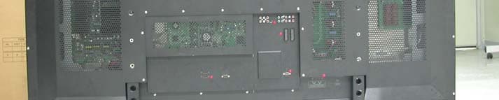
Click to zoom
Application Details
- Equipment Class
- JBP - Part 15 Class B Computing Device Peripheral
- Date of Grant
- Sep 06, 2006
- Application Purpose
- Original Equipment
- Date of Application
- Sep 06, 2006
- Equipment Note
- Plasma Monitor
- Company
- LG Electronics USA, Inc.
- Country
- United States
Documents & Files
Document Text
Text extracted from the exhibit documents filed with the FCC. Open a document above to read the original.
Users Manual
Please read this manual carefully before operating your set. Retain it for future reference. Record model number and serial number of the set. See the label attached on the back cover and quote this information to your dealer when you require service. ENERGYSTAR is a set of power-saving guidelines issued by the U.S. Environmental Protection Agency(EPA). As an ENERGY STAR Partner LGE U. S. A.,Inc. has determined that this product meets the ENER- GY STAR guidelines for energy efficiency. P/NO : 38289U0558C Printed in Korea OWNER’S MANUAL PLASMA TV MODELS: 71PY1M 2 Plasma Monitor Warning/Caution WARNING/CAUTION: TO REDUCE THE RISK OF ELECTRIC SHOCK DO NOT REMOVE COVER (OR BACK). NO USER SERVICEABLE PARTS INSIDE. REFER TO QUALIFIED SERVICE PERSONNEL. The lightning flash with arrowhead symbol, within an equilateral triangle, is intended to alert the user to the presence of uninsulated “dangerous voltage” within the product’s enclosure that may be of suffi- cient magnitude to constitute a risk of electric shock to persons. The exclamation point within an equilateral triangle is intended to alert the user to the presence of important operating and maintenance (servicing) instructions in the literature accompanying the appli- ance. WARNING/CAUTION: TO PREVENT FIRE OR SHOCK HAZARDS, DO NOT EXPOSE THIS PRODUCT TO RAIN OR MOISTURE. FCC NOTICE • A Class B digital device This equipment has been tested and found to comply with the limits for a Class B digital device, pursuant to Part 15 of the FCC Rules. These limits are designed to provide reasonable protection against harmful interference in a residential installation. This equipment generates, uses and can radiate radio frequency energy and, if not installed and used in accordance with the instructions, may cause harmful interference to radio communications. However, there is no guarantee that interference will not occur in a particular installation. If this equipment does cause harmful interference to radio or television reception, which can be determined by turning the equipment off and on, the user is encouraged to try to correct the interference by one or more of the following measures: - Reorient or relocate the receiving antenna. - Increase the separation between the equipment and receiver. - Connect the equipment into an outlet on a circuit different from that to which the receiver is connected. - Consult the dealer or an experienced radio/TV technician for help. • Any changes or modifications not expressly approved by the party responsible for compli- ance could void the user’s warranty. CAUTION: Do not attempt to modify this product in any way without written authorization from LG Electronics. Unauthorized mod- ification could void the user’s warranty. WARNING/CAUTION TO REDUCE THE RISK OF FIRE AND ELECTRIC SHOCK, DO NOT EXPOSE THIS PRODUCT TO RAIN OR MOISTURE. W W arning/Caution arning/Caution Owner’s Manual 3 Safety Instructions IMPORTANT SAFETY INSTRUCTIONS Important safety instructions shall be provided with each apparatus. This information shall be given in a separate booklet or sheet, or be located before any operating instructions in an instruction for installation for use and supplied with the appara- tus. This information shall be given in a language acceptable to the country where the apparatus is intended to be used. The important safety instructions shall be entitled “Important Safety Instructions”. The following safety instructions shall be includ- ed where applicable, and, when used, shall be verbatim as follows. Additional safety information may be included by adding statements after the end of the following safety instruction list. At the manufacturer’s option, a picture or drawing that illus- trates the intent of a specific safety instruction may be placed immediately adjacent to that safety instruction : 1. Read these instructions. 2. Keep these instructions. 3. Heed all warnings. 4. Follow all instructions. 5. Do not use this apparatus near water. 6. Clean only with dry cloth. 7. Do not block any ventilation openings. Install in accordance with the manufacturer’s instructions. 8. Do not install near any heat sources such as radiators, heat registers, stoves, or other apparatus (including ampli-fiers) that produce heat. 9. Do not defeat the safety purpose of the polarized or grounding-type plug. A polarized plug has two blades with one wider than the other. A grounding type plug has two blades and a third grounding prong, The wide blade or the third prong are provided for your safety. If the provided plug does not fit into your outlet, consult an electrician for replacement of the obso- lete outlet. 10. Protect the power cord from being walked on or pinched particularly at plugs, convenience receptacles, and the point where they exit from the apparatus. 11. Only use attachments/accessories specified by the manufacturer. 12. Use only with the cart, stand, tripod, bracket, or table specified by the manufacturer, or sold with the apparatus. When a cart is used, use caution when moving the cart/apparatus combination to avoid injury from tip-over. Safety Instructions Safety Instructions PORTABLE CART WARNING 4 Plasma Monitor Safety Instructions 13. Unplug this apparatus during lightning storms or when unused for long periods of time. 14. Refer all servicing to qualified service personnel. Servicing is required when the apparatus has been damaged in any way, such as power-supply cord or plug is damaged, liquid has been spilled or objects have fallen into the apparatus, the apparatus has exposed to rain or moisture, does not operate normally, or has been dropped. 15. CAUTION concerning the Power Cord : Most appliances recommend they be connected to a dedicated circuit; that is, a single outlet circuit which pow- ers only that appliance and has no additional outlets or branch circuits. Check the specification page of this owner's manual to be certain. - This may cause a fire or an electric shock. Do not overload wall outlets. Ove…
Text truncated - open the document above for the full version.
Users Manual
8 Plasma Monitor Introduction Controls Controls INPUT MENU VOL TruSurround XT Front Panel Controls Front Panel Controls MENU Button INPUT Button VOLUME (FF,GG) Buttons EE, DDButtons INDEX Switches LED Display on or off. Remote Control Sensor Power Indicator Illuminates red in standby mode, Illuminates green when the monitor is turned on. Sub power Button Owner’s Manual 9 Introduction Connection Options Connection Options DIGITAL AUDIO OUT OPTICAL HDMI/DVI IN HDMI/DVI IN 1 2 RS-232C INRS-232C IN (CONTROL & SERVICE) VIDEOVIDEO AUDIO COMPONENTCOMPONENT IN IN VIDEOVIDEOAUDIOAUDIO MONO ( ) S-VIDEOS-VIDEO VIDEO IN VIDEO IN 3VIDEO IN 3VIDEO IN 4VIDEO IN 4 AUDIO (RGB/DVI)AUDIO (RGB/DVI) RGB INRGB IN RGB(PC/DTV)RGB(PC/DTV) REMOTE REMOTE CONTROL INCONTROL IN Back Connection Panel Back Connection Panel 1 6 2 5 7 3 4 HDMI/DVI IN Connect a HDMI signal to 1 or 2. Or DVI (VIDEO)signal to the 1 port with a DVI to HDMI cable. RS-232C IN (CONTROL & SERVICE) PORT Connect to the RS-232C port on a PC. VIDEO IN Connect audio/video output from an external device to these jacks. S-VIDEO Connect S-Video out from an S-VIDEO device. COMPONENT IN Connect a component video/audio device to these jacks. EURO SCART SOCKET Connect the euro scart of the VCR to these sockets. RGB IN AUDIO (RGB/DVI) Connect the monitor output from a PC to the appropriate input port. RGB(PC/DTV) Connect the monitor output from a PC to the appropriate input port. Remote Control Port Connect your wired remote control. 1 7 2 3 4 5 6 10 Plasma Monitor Introduction - When using the remote control, aim it at the remote control sensor on the monitor. - Under certain conditions such as if the remote IR signal is interrupted, the remote control may not function. Press the key again as necessary. Remote Control Key Functions Remote Control Key Functions LIGHT INPUT MODE PIP MUTE SLEEP VOLCH WIN. SIZE WIN. POSITION SWAP MENU PIP INPUTARC EXIT PLAYPAUSESTOP RECORD VIDEOCOM1RGB HDMI1 ENTER HDMI2KEY LOCK INDEX REWFFSKIP POWER DW D A S P APC COM2 LIGHT Illuminates the remote control buttons. MODE Selects the remote operating mode: MNT, VCR, DVD, CABLE, HDSTB or AUDIO. INPUT Selects: Video1-2-3-4, Component 1-2, RGB-DTV (or RGB- PC), DVI-DTV (or DVI-PC), HDMI input sources. POWER Turns your monitor or any other programmed equipment on or off, depending on mode. PIP Selects the PIP mode. DW Selects the DW mode. WIN. SIZE Adjusts the sub picture size. NUMBER buttons Dosen’t work for monitor mode. WIN.POSITION Moves the sub picture. SWAP Exchanges the main/sub images. XD Switches the XD on or off.(Refer to p. 19) MENU Brings up the main menu to the screen. PIP INPUT Selects the input source for the sub picture. ARC Changes the picture format. (Refer to p. 25) EXIT Clears all on-screen displays and returns to monitor viewing from any menu. Owner’s Manual 11 Installing Batteries • Open the battery compartment cover on the back side and install the batteries matching correct polarity (+ with +, - with -). • Install two 1.5V AA batteries. Don’t mix old or used batteries with new ones. Replace cover. THUMBSTICK (Up/Down/Left/Right/ENTER) Navigate the on-screen menus and adjust the system settings to your preference. KEY LOCK Switches the key lock on or off. INDEX Switches LED Display on or off. DASP To select the sound appropriate to your viewing program character: SRS TSXT, Flat, Music, Cinema, Sports, or User (Refer to p.21) MUTE Switches the sound on or off. SLEEP Sets the Sleep Timer. VOLUME UP/DOWN Increases/decreases the sound level. CHANNEL UP/DOWN Selects available channels. Dosen’t work for monitor mode. LIGHT INPUT MODE PIP MUTE SLEEP VOLCH WIN. SIZE WIN. POSITION SWAP MENU PIP INPUTARC EXIT PLAYPAUSESTOP RECORD VIDEOCOM1RGB HDMI1 ENTER HDMI2KEY LOCK INDEX REWFFSKIP POWER DW D A S P APC COM2 VIDEO/COM1/COM2/RGB/HDMI1/HDMI2 Selects: Video1-2-3-4, Component 1-2, RGB-DTV (or RGB- PC),HDMI1, HDMI2 input sources. VCR/DVD/DVHS/Camcorder BUTTONS Control some video cassette recorders or DVD players ("RECORD" button is not available for DVD player). 12 Plasma Monitor Installation 4 inches 4 inches 4 inches4 inches 2 inches W W all Mount Installation all Mount Installation For proper ventilation, allow a clearance of 4” on each side and 2” from the wall. Detailed installation instruc- tions are available from your dealer, see the optional Wall Mounting Bracket Installation and Setup Guide. Installation Instructions Installation Instructions •Install this monitor only in a location where adequate ventilation is available. GROUNDING Ensure that you connect the grounding / earth wire to prevent possible electric shock. If grounding methods are not possible, have a qualified electrician install a separate circuit breaker. Do not try to ground the unit by connecting it to telephone wires, lightening rods, or gas pipes. Power Supply Short-circuit Breaker Desktop Pedestal Installation Desktop Pedestal Installation For proper ventilation, allow a clearance of 4” on each side and the top, 2.36” on the bottom, and 2” from the wall. Detailed installation instructions are included in the optional Desktop Stand Installation and Setup Guide available from your dealer. Owner’s Manual 13 Installation External Equipment Connections External Equipment Connections NOTE: Not all cables shown are included with the plasma display. - To avoid picture noise (interference), leave an adequate distance between the VCR and Monitor. - Use the ISM Method feature to avoid having a fixed image remain on the screen for a long period of time. Typically a frozen still picture from a VCR. If the 4:3 picture format is used; the fixed image may remain visible on the screen. How to connect 1. Connect the audio and video cables from the VCR's output jacks to the monitor input jacks, as shown in the figure. When connecting the monitor to VCR, match the jack colors (Video = yellow, Audio Left = white, and Audio Right = red). 2. If you connect an S-VIDEO output from VCR to the S- VIDEO input, the picture q…
Text truncated - open the document above for the full version.
Users Manual
16 Plasma Monitor Installation How to connect 1. To get the best picture quality, adjust the PC graphics card to a 1600x1200, 60Hz. 2. Use the monitor’s RGB INPUT or HDMI1 port for video connections, depending on your PC connec- tor. If the graphic card on the PC does not output ana- log and digital RGB simultaneously, connect only one of either RGB INPUT or HDMI1 INPUT to dis- play the PC on the monitor. If the graphic card on the PC does output analog and digital RGB simultaneously, set the monitor to either RGB or HDMI1; (the other mode is set to Plug and Play automatically by the monitor.) 3. Then, make the corresponding audio connections. If using a sound card, adjust the PC sound as required. How to use 1. Turn on the PC and the monitor. 2. Turn on the display by pressing the POWER button on the monitor's remote control. 3. Use the INPUTbutton on the remote control to select RGBor HDMI1. 4. Check the image on your monitor. There may be noise associated with the resolution, vertical pattern, contrast or brightness in PC mode. If noise is present, change the PC mode to another resolution, change the refresh rate to another rate or adjust the brightness and contrast on the menu until the picture is clear. If the refresh rate of the PC graphic card can not be changed, change the PC graphic card or consult the manufacturer of the PC graphic card. NOTES:• Use a HDMI to DVI cable. • Avoid keeping a fixed image on the monitor's screen for a long period of time. The fixed image may become permanently imprinted on the screen. Use the Orbiter screen saver when possible. • The synchronization input form for Horizontal and Vertical frequencies is separate. PC Setup PC Setup AUDIO (RGB/DVI)AUDIO (RGB/DVI) RGB IN RGB(PC/DTV)RGB(PC/DTV) REMOTE CONTROL IN HDMI/DVI IN 1 2 RS-232C IN (CONTROL & SERVICE) - This monitor provides Plug and Play capability, meaning that the PC adjusts automatically to its settings. The monitor sends configuration information (EDID) to the PC using the Video Electronics Standard Association (VESA) Display Data Channel (DDC) protocol. - The monitor perceives 640x480, 60Hz as DTV 480p based on the PC graphic card. In this case, change the screen scanning rate for the graphic card. External Equipment Connections External Equipment Connections Owner’s Manual 17 Installation Monitor Display Specifications (RGB-PC / DVI-PC Mode) Resolution 720x400 640x480 800x600 Horizontal Frequency(KHz) 31.469 31.469 35.000 37.861 37.500 43.269 37.879 46.875 53.674 49.725 48.363 56.476 60.023 63.981 80.000 75.00 66.587 70.08 59.94 66.66 72.80 75.00 85.00 60.31 75.00 85.06 74.55 60.00 70.06 75.02 60.02 75.00 60.00 59.934 Vertical Frequency(Hz) 832x624 1024x768 1600x1200 1920x1080 1280x1024 - HDMI TM , the HDMI logo and High-Definition Multimedia Interface are trademarks or registered trademarks of HDMI Licensing LLC." - This monitor can receive the High-Definition Multimedia Interface(HDMI). - This monitor supports HDCP(High-bandwidth Digital Contents Protection) Protocol for 480p, 720p, 1080i, 1080p modes. - When you Connect with HDMI Source Devices (DVD Player or Set Top Box) supporting Auto HDMI function, automatical- ly, support Plug & Play and then set the HDMI Source Devices(1920 x 1080i). After reading in HDMI Source Devices using Display Data Channel(DDC) Protocol, EDID stored in monitor is used. If HDMI Source Devices not supported Auto HDMI is been, the Resolution is setted, manually. - To get the best picture quality, adjust the DVD Player or Set Top Box output resolution to 1920 x 1080i. How to connect When Source Devices(DVD Player or Set Top Box) support HDMI. - If Source Devices have HDMI Output Connector, Source Devices connect to DTV with HDMI Cable .(not supplied with the product). - If Source Devices support Auto HDMI, automatically, Source Devices divert output resolution in 1920 x 1080i. But if not, resolution divert Manually Setting for reference Manual of Source Devices. - To get the best picture quality, adjust the DVD Player or Set Top Box output resolution to 1920 x 1080i. - Because HDMI sends Digital Video and Audio with one cable, need not especial Audio Cable for using HDMI Cable. 18 Plasma Monitor Operation Operation Operation Menu Language Selection Menu Language Selection T T urning on the Monitor urning on the Monitor Turning on the Monitor just after installation 1. Connect power cord correctly. At this moment, the Monitor is switched to standby mode. 2. Press the INPUT or button on the Monitor or press the POWER, INPUTbutton on the remote control and then the Monitor will switch on. -The menus can be shown on the screen in the selected language. First select your language. 1. Press the MENUbutton and then use DD / EE button to select the SPECIALmenu. 2. Press the GGbutton and then use DD / EE button to select Language. 3. Press the GGbutton and then use DD / EE button to select your desired language. From this point on, the on-screen menus will be shown in the language of your choice. 4. Press the ENTERbutton to save. • Press the MENUbutton to return to the previous menu. Owner’s Manual 19 Operation 1. Press the APCbutton repeatedly to select the picture appearance setup option as shown below. APC (Auto Picture Control) APC (Auto Picture Control) - To initialize values (reset to default settings), select the Normaloption. 1. Press the MENUbutton and then use DD / EE button to select the PICTUREmenu. 2. Press the GGbutton and then use DD / EE button to select ACC. 3. Press the GGbutton and then use DD / EE button to select either Cool (Preset), Normal (Default), Warm (Preset). 4. Press the ENTERbutton to save the new settings. Auto Color Auto Color T T emperature Control emperature Control - APC adjusts the Monitor for the best picture appearance. - When adjusting Picture menu options (contrast, brightness, color, sharpness, and tint) manually, APC automati- cally changes to Off. - Readjust Picture menu settings for each following input source as preferred. Pic…
Text truncated - open the document above for the full version.
Block Diagram
Great Company Great People Blue Ocean P³ Innovation ▣ 71PY1M 블럭다이어 그램 Scaler GF9351 Noise Reduction Detail Enhancement Video Mixer Edge & Motion Adaptive Deinterlacer Including Film Motion Detection OSD Mix Core Processing Scaler2Scaler1 Input A Black Level Removal CSC Picture Level Control Input B Black Level Removal CSC Picture Level Control Decoder TVP5160 Decoder TVP5160 Deinterlacer FRC9429 ADC AD9984 ADC AD9984 HDMI RX ANX9021 HDMI RX ANX9021 IEP3 LGDP4412 LVDS TX THC63LVD1023 Composite : 480i,576iDTV : 480i/P,576i/P,720P,1080i/P PC : 1920X1080 at 60Hz단,RGB와 COMPONENT의 1080P 수신 시에 ADC 9bit 출력 AV1AV2AV3AV4Component1Component2RGB-DsubHDMI1HDMI2AV1(S-Video) 10bit 656 10bit YCbCr/RGB 10bit YCbCr/RGB 10bit YCbCr/RGB 10bit YCbCr/RGB 20bit 601 20bit RGB 8bit RGB Gamma LUT CSC 2D Non linear scaler Output Processing 480i/576i Silicon Image LG 27 Mhz 27 Mhz 27 Mhz 27 Mhz 54 Mhz 54 Mhz 27 Mhz 27 Mhz 27 Mhz 27 Mhz
Cover Letter(s)
LG Electronics USA 1000 Sylvan Avenue Englewood Cliffs, NJ 07632 Date: Sep 6,2006 Compliance Certification Services Certification Division 561F Monterey Road Morgan Hill, CA 95037 To whom it may concern: We, the undersigned, hereby authorize <ESTECH CO.,Ltd.>, to act on our behalf in all manners relating to application for equipment authorization, including signing of all documents relating to these matters. Any and all acts carried out by <ESTECH CO., Ltd.> on our behalf shall have the same effect as acts of our own. We, the undersigned, hereby certify that we are not subject to a denial of federal benefits, that includes FCC benefits, pursuant to Section 5301 of the Anti-Drug Abuse Act of 1988, 21 U.S.C. 853(a). In authorizing <ESTECH CO.,Ltd.> as our agent, we still recognize that we are responsible to: a) comply with the relevant provisions of the certification program; b) make all necessary arrangements for the conduct of the evaluation, including provision for examining documentation and access to all areas, records (including internal audit reports) and personnel for the purposes of evaluation (e.g. testing, inspection, assessment, surveillance, reassessment) and resolution of complaints; c) make claims regarding certification only in respect of the scope for which certification has been granted; d) do not use our product certification in such a manner as to bring the Certification Division into disrepute and not make any statement regarding our product certification which the Certification Division may consider misleading or unauthorized; e) upon suspension or cancellation of certification, discontinue use of all advertising matter that contains any reference thereto and return any certification documents as required by the Certification Division; f) use certification only to indicate the products are certified as being in conformity with specified standards; g) endeavor to ensure that no certificate or report nor any part thereof is used in a misleading manner; h) ensure that any reference to our product certification in communication media such as documents, brochures or advertising, complies with the requirements of the Certification Division; i) keep a record of all complaints made known to the us relating to the product’s compliance with requirements of the relevant standard and to make these records available to the Certification Division when requested; j) take appropriate action with respect to such complaints and any deficiencies found in products or services that affect compliance with the requirements for certification; k) document the actions taken. This authorization is valid until further written notice from the applicant. Sincerely Yours, Sang-Wook Lee/Manager Engineer Tel:82-54-470-4532 REMARK: 1. This authorization letter will be sent along with your application when filing with the Certification Division. 2. Please follow the format and type it on company letterhead and send original to us.
Cover Letter(s)
Helen Zhao To: [email protected] Subject: RE: LG Electronics USA, FCC ID: BEJ71PY1MWA, Assessment NO.: AN06T6109 9/7/2006 From: jmyang Sent: Wednesday, September 06, 2006 6:48 PM To: Helen Zhao Subject: FW: LG Electronics USA, FCC ID: BEJ71PY1MWA, Assessment NO.: AN06T6109 Dear Helen Zhao, Please see my reply as below. Question #1: On the block diagram, please indicate the local oscillator/crystal frequencies, please specify the highest frequency. Please make sure radiated emission has been measured up to the upper frequency of measurement range shown in the table under FCC15.33(b)(1). Answer: Please find the revised block diagram Question #2: Please update the test report to clearly indicate whether any ferrite core is incorporated with each I/O cable. You can also provide the external photos of the I/O cables and power cord. Answer: Please see the revised test report. Question #3: This is for your information. For this type of devices, schematic diagram and operational description are not required, howver you can choose to submit anyway. My question is whether you want to submit Request for confidentiality letter. If so, please send me the letter. If you decide not to upload schematic diagram and operational description to FCC, please let me know, so I will ignore these documents. Answer: Please ignore these two documents. The items indicated above must be submitted before processing can continue on the above referenced application. Failure to provide the requested information within 30 days of the original e-mail date may result in application dismissal and forfeiture of the filing fee. Also, please note that partial responses increase processing time and should not be submitted. Any questions about the content of this correspondence should be directed to the e-mail address listed below the name of the sender.
External Photos
1. FRONT 2. REAR
Internal Photos
INTERNAL PHOTO 1. MAIN 1.1 Front 1.2 Rear 2. POWER 2.1 Front 2.2 Rear 2.3 Front 2.4 Rear 3. Y_SUS 3.1 Front 3.2 Rear 4.Z_SUS 4.1 Front 4.2 Rear 5.CTRL_LVDS 5.1 Front 5.2 Rear 6. PDP 6.1 Front 6.2 Rear
Test Report
Test Report for FCC Company name Address Telephone Product name Basic Model Additional Model Test date Testing location Standard □ Class A ■ Class B Test resultOK □ Class A ■ Class B Test resultOK Tested by Reviewed by Abbreviation * Note - Basic Model : 71PY1M-WA Additional Model : 71PY1MG-WA - Basic Model and Addition Models are same product,only case color of the product is different. - This test report is not permitted to copy partly without our permission - This test result is dependent on only equipment to be used - This test result based on a single evaluation of one sample of the above mentioned OK, Pass = Passed, Fail = Failed, N/A = not applicable LG Electronics USA 1000 Sylvan Avenue Englewood Cliffs, NJ 07632 1-201-266-2420 Measurement facility registration number Engineer J.H.Kim Manager Engineer J.M.Yang 94696 (Signature) (Signature) Date of issue ESTECH Co., Ltd. 97-1 Hoiuk-Ri Majang-Myon, Icheon-city, KyungKi-Do, Korea Test item ■ Conducted Emission ■ Radiated Emission FCC PART 15 2006 , ANSI C 63.4 2003 , ICES-003 2006-8-21~2006-8-24 71PY1M-WA 71PY1MG-WA LG Electronics Inc. KOREA Report Number : ESTF150608-010 , Web : www. estech. co. kr Page 1 of 15 Report NumberESTF150608-010 Manufacturer Country of origin Applicant Product 30-Aug-06 Plasma Monitor 3 4 5 6 8 8 8 9 10 11 11 11 12 13 15 Appendix 1. Spectral diagram 5.3 Test data ................................................................................................ ... 7. Photographs of test setup ................................................................................. 8. Photographs of EUT .......................................................................................... 6. Measurement of conducted emission .................................................................. 6.1 Measurement equipment .............................................................................. 6.2 Environmental conditions .............................................................................. 6.3 Test data ................................................................................................... Report Number : ESTF150608-010 , Web : www. estech. co. kr Page 2 of 15 5. Measurement of radiated emission ..................................................................... 5.1 Measurement equipment .............................................................................. Contents 1. Laboratory Information .................................................................................... 2. Descri ption of EUT .......................................................................................... 3. Test Standards ................................................................................................ 4. Measurement condition .................................................................................... 5.2 Environmental conditions .............................................................................. 5.4 Test data ................................................................................................... 1. Laboratory Information 1.1 General 1.2 Test Lab. Corporation Name : ESTECH Co. Ltd Head Office : Rm 1015, World Venture Center II, 426-5, Gasan-dong, Geumcheon-gu, Seoul, Korea (Safety & Telecom. Test Lab) EMC Test Lab : 58-1 Osan-Ri, GaNam-Myon, YeoJoo-Gun, KyungKi-Do, Korea 97-1 Hoiuk-Ri Majang-Myon, Icheon-city, KyungKi-Do, Korea 1.3 Official Qualification(s) MIC : Granted Accreditation from Ministry of Information & Communication for EMC, Safety and Telecommunication KOLAS : Accredited Lab By Korea Laboratory Accreditation Schema base on CENELEC requirements FCC : Filed Laboratory at Federal Communications Commission VCCI : Granted Accreditation from Voluntary Control Council for Interference from ITE This EUT (Equipment Under Test) has been shown to be capable of compliance with the applicable technical standards and is tested in accordance with the measurement procedures as indicated in this report.ESTECH Lab attests to accuracy of test data. All measurement reported herein were performed by ESTECH Co., Ltd. ESTECH Lab assume full responsibility for the completeness of these measurements and vouch for the qualifications of all persons taking them. Report Number : ESTF150608-010 , Web : www. estech. co. kr Page 3 of 15 2. Description of EUT 2.1 Summary of Equipment Under Test NONE: Model Number : 71PY1M-WA Serial Number : Manufacturer : Country of origin : Rating : Receipt Date : 2.2 General descriptions of EUT Using Freq. : 6MHz, 14.3MHz(2EA),18.43MHz,20.25MHz, 27MHz(2EA),54MHz Report Number : ESTF150608-010 , Web : www. estech. co. kr Page 4 of 15 Plasma Monitor NONE LG Electronics Inc. KOREA INPUT:AC120V / 60Hz 2006-08-16 3. Test Standards Test Standard : FCC PART 15 (2006) & ICES-003 Test Method : ANSI C 63.4 (2003) This standard sets forth uniform methods of measurement of radio-frequency (RF) signals and noise emitted from both unintentional and intentional emitters of RF energy in the frequency range 9 kHz to 40 GHz. Methods for the measurement of radiated and AC power-line conducted radio noise are covered and may be applied to any such equipment unless otherwise specified by individual equipment requirements. These methods cover measurement of certain decides that deliberately radiate energy, such as intentional emitters, but does not cover licensed transmitters. This standard is not intended for certification/approval of avionic equipment or for industrial, scientific, and medical (ISM) equipment These method apply to the measurement of individual units or systems comprised of multiple units This Standard sets out the regulations under which an intentional, unintentional, or incidental radiator may be operated without an individual license. It also contains the technical specifications, administrative requirements and other conditions relating to the marketing of Part 15 devices. Report Number : ESTF150608-010 , Web : www. estech. co. kr Page…
Text truncated - open the document above for the full version.
Test Setup Photos
TEST SETUP PHOTO 1. Conducted Emission setup pho…
Text truncated - open the document above for the full version.
Contact Information
Applicant
David Kim(Team leader, LGEUS NA Policy & Regulatory Affairs)
Test Firm
Estech Co., Ltd.Ike Chung
Technical Specifications
| # | Rule Parts | Frequency Range | Power Output |
|---|---|---|---|
| 1 | 15B | - | - |
Other Applications from LG Electronics USA, Inc.

BEJTFHOBINI1F1
Jan 08, 2025Telematics
Equipment Class
DTS - Digital Transmission SystemBEJNT-16Z90TS
Oct 02, 2024Notebook Computer
Equipment Class
DSS - Part 15 Spread Spectrum TransmitterBEJSP-PEW8
Sep 26, 2024Stylus Pen
Equipment Class
DCD - Part 15 Low Power Transmitter Below 1705 kHzBEJ-RSMV2
Sep 24, 2024RF Module
Equipment Class
FDS - Part 15 Field Disturbance SensorBEJTFBMEIBN3EU
Sep 24, 2024Telematics
Equipment Class
NII - Unlicensed National Information Infrastructure TX