BEJ9QKE40650DVD Recorder
LG Electronics USA, Inc.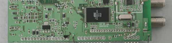
Click to zoom
Application Details
- Equipment Class
- HID - Part 15 TV Interface Device
- Date of Grant
- Jan 04, 2007
- Application Purpose
- Original Equipment
- Date of Application
- Jan 04, 2007
- Equipment Note
- DVD Recorder
- Frequency Range
- 67.25000000 - 71.75000000
- Company
- LG Electronics USA, Inc.
- Country
- United States
Documents & Files
Document Text
Text extracted from the exhibit documents filed with the FCC. Open a document above to read the original.
Users Manual
DR298H-M_HA1ULL-ENG DVD RECORDER OWNER’S MANUAL MODEL: DR787T Before connecting, operating or adjusting this product, please read this instruction booklet carefully and completely. Call us and we will guide you through your first recording, for free. 1-800-243-0000 2 This lightning flash with arrowhead symbol within an equilateral triangle is intended to alert the user to the presence of uninsulated dangerous voltage within the product’s enclosure that may be of sufficient magnitude to constitute a risk of electric shock to persons. The exclamation point within an equilateral triangle is intended to alert the user to the presence of important operating and maintenance (servicing) instructions in the literature accompanying the product. WARNING:TO PREVENT FIRE OR ELECTRIC SHOCK HAZARD, DO NOT EXPOSE THIS PRODUCT TO RAIN OR MOISTURE. WARNING:Do not install this equipment in a confined space such as a book case or similar unit. CAUTION: Do not block any ventilation openings. Install in accordance with the manufacturer's instructions. Slots and openings in the cabinet are provided for ventilation and to ensure reliable operation of the product and to protect it from over heating. The openings should be never be blocked by placing the product on a bed, sofa, rug or other similar surface.This product should not be placed in a built-in installation such as a bookcase or rack unless proper ventilation is provided or the manufacturer's instruction have been adhered to. CAUTION: CLASS 3B VISIBLE AND INVISIBLE LASER RADIATION WHEN OPEN AND INTERLOCKS DEFEATED AVOID EXPOSURE TO THE BEAM. CAUTION: This product employs a Laser System. To ensure proper use of this product, please read this owner’s manual carefully and retain it for future reference. Should the unit require maintenance, contact an authorized service center. Performing controls, adjustments, or carrying out procedures other than those specified herein may result in hazardous radiation exposure. To prevent direct exposure to laser beam, do not try to open the enclosure. Visible laser radiation when open. DO NOT STARE INTO BEAM. CAUTION: The apparatus should not be exposed to water (dripping or splashing) and no objects filled with liquids, such as vases, should be placed on the apparatus. CAUTION concerning the Power Cord Most appliances recommend they be placed upon a dedicated circuit; That is, a single outlet circuit which powers only that appliance and has no additional outlets or branch circuits. Check the specification page of this owner's manual to be certain. Do not overload wall outlets. Overloaded wall outlets, loose or damaged wall outlets, extension cords, frayed power cords, or damaged or cracked wire insulation are dangerous. Any of these conditions could result in electric shock or fire. Periodically examine the cord of your appliance, and if its appearance indicates damage or deterioration, unplug it, discontinue use of the appliance, and have the cord replaced with an exact replacement part by an authorized servicer. Protect the power cord from physical or mechanical abuse, such as being twisted, kinked, pinched, closed in a door, or walked upon. Pay particular attention to plugs, wall outlets, and the point where the cord exits the appliance. To disconnect power from the mains, pull out the mains cord plug. When installing the product, ensure that the plug is easily accessible. FCC WARNING: This equipment may generate or use radio frequency energy. Changes or modifications to this equipment may cause harmful interference unless the modifications are expressly approved in the instruction manual. The user could lose the authority to operate this equipment if an unauthorized change or modification is made. REGULATORY INFORMATION: FCC Part 15 This equipment has been tested and found to comply with the limits for a Class B digital device, pursuant to Part 15 of the FCC Rules. These limits are designed to provide reasonable protection against harmful interference in a residential installation. This equipment generates, uses and can radiate radio frequency energy and, if not installed and used in accordance with the instructions, may cause harmful interference to radio communications. However, there is no guarantee that interference will not occur in a particular installation. If this equipment does cause harmful interference to radio or television reception, which can be determined by turning the equipment off and on, the user is encouraged to try to correct the interference by one or more of the following measures: • Reorient or relocate the receiving antenna. • Increase the separation between the equipment and receiver. • Connect the equipment into an outlet on a circuit different from that to which the receiver is connected. • Consult the dealer or an experienced radio/TV technician for help. FCC COMPLIANCE:The responsible party for this product’s compliance is: LG Electronics U.S.A., Inc.,1000 Sylvan Avenue, Englewood Cliffs, NJ. Phone: 1-201-816-2000. CAUTION RISK OF ELECTRIC SHOCK DO NOT OPEN CAUTION: TO REDUCE THE RISK OF ELECTRIC SHOCK DO NOT REMOVE COVER (OR BACK) NO USER-SERVICEABLE PARTS INSIDE REFER SERVICING TO QUALIFIED SERVICE PERSONNEL . 3 Introduction 1. Read these instructions. - All these safety and operating instructions should be read before the product is operated. 2. Keep these instructions. - The safety, operating and use instructions should be retained for future reference. 3. Heed all warnings. - All warnings on the product and in the operating instructions should be adhered to. 4. Follow all instructions. - All operating and use instructions should be followed. 5. Do not use this apparatus near water. – For example: near a bath tub, wash bowl, kitchen sink, laundry tub, in a wet basement; or near a swimming pool; and other areas located near water. 6. Clean only with dry cloth. – Unplug this product from the wall outlet before cleaning. Do not use liquid cleaners. 7. Do not block any ventilation open…
Text truncated - open the document above for the full version.
Cover Letter(s)
LG Electronics Inc. attn: Reviewing Engineer MET Laboratories, Inc. 914 West Patapsco Avenue Baltimore, MD 21230-3432 RE: LETTER OF AGENT AUTHORIZATION To Whom It May Concern: We, the undersigned, hereby authorize MET Laboratories, Inc. to act on our behalf in all matters relating to application for equipment authorization, including the signing of all document s relating to these matters. We also hereby certify that no party to the application authorized hereunder is subject to t he denial of benefits, including FCC benefits, pursuant to Section 5301 of the Anti-Drug Abuse Act of 1988,21 U.S.C.853(a). This agreement expires one year from the current date. Sincerely, Jonghoon Park/ Chief Engineer December 27, 2006 LG Electronics Inc. Digital Media Company [email protected] 19-1 Cheongho-ri, Jinwi-myeon, Pyeongtaek-si, Gyeonggi-do, 451-713, Korea
Cover Letter(s)
LG Electronics Inc. Attn: Reviewing Engineer MET Laboratories, Inc. 914 West Patapsco Avenue Baltimore, MD 21230-3432 RE: CONFIDENTIALITY REQUEST FOR DVD Player / Video Cassette Recorder FCC ID: BEJ9QKE40650 MODEL #: TMVA-L102F To Whom It May Concern: This letter served as an official request for confidentiality under FCC Rule section 0.459. We have requested that the schematic diagrams and block diagram required to be submitted with this application be withheld from public review. These documents contains detailed system and equipment description and related information about the product which LG Electronics Inc. considers to be proprietary, confidential, and a custom design and, otherwise would not release to the general public. Since this design is a basis from which future technological products will evolve, LG Electronics Inc. feels that this information would be of benefit to its competitors, and that the disclosure of the information in these document would give our competitors an unfair advantage in the market. Please contact me if there is any information you may need. Sincerely, Jonghoon Park/ Chief Engineer December 27, 2006 LG Electronics Inc. Digital Media Company [email protected]
Operational Description
S P E C I F I C A T I O N LG InnotekCo., Ltd. ApprovedCheckedDesigned Model No. TMVA-L102F Document No. XC40002 NTSC/ATSC Module TMVA-L102F Dec 21, 2006 Index 1. Features ................................................................................................... 3/29 2. Ordering information ---------------------------------------------------------------------------------3/29 3. Label marking ------------------------------------------------------------------------------------------3/29 4. General specifications -------------------------------------------------------------------------------4/29 4-1. Supporting system ----------------------------------------------------------------------------4/29 4-2. Receiving frequency --------------------------------------------------------------------------4/29 4-3. 1’st IF center frequency ----------------------------------------------------------------------4/29 4-4. Input signal level -------------------------------------------------------------------------------4/29 4-5. Input/ Output condition -----------------------------------------------------------------------4/29 4-7. Communication Speed -----------------------------------------------------------------------4/29 4-8. Others ---------------------------------------------------------------------------------------------4/29 5. Operating test conditions ----------------------------------------------------------------------------4/29 5-1. Voltage -------------------------------------------------------------------------------------------4/29 5-2. Operating temperature ------------------------------------------------------------------------4/29 5-3. Operating humidity -----------------------------------------------------------------------------4/29 6. Storage test conditions -------------------------------------------------------------------------------4/29 7. Standard test conditions ------------------------------------------------------------------------------5/29 7-1. Ambient condition -----------------------------------------------------------------------------5/29 7-2. Power supply voltages ------------------------------------------------------------------------5/29 7-3. Current consumption --------------------------------------------------------------------------5/29 8. Electrical characteristics ------------------------------------------------------------------------------6/29 8-1. Loop-through section characteristics -------------------------------------------------------6/29 8-2. RF-Modulator section characteristics ------------------------------------------------------7/29 8-3. NTSC demodulation section characteristics ----------------------------------------------9/29 8-4. ATSC demodulation section characteristics ----------------------------------------------10/29 8-5. QAM demodulation section characteristics -----------------------------------------------10/29 9. PLL descriptions ---------------------------------------------------------------------------------------11/29 9-1. Tuner section registers------------------------------------------------------------------------11/29 9-1-1. Address field ------------------------------------------------------------------------------11/29 9-1-2. Serial Communications registermap -----------------------------------------------11/29 9-1-3. register descriptions -------------------------------------------------------------------12/29 10. Environment tests -----------------------------------------------------------------------------------17/29 10-1. Signal conditions -----------------------------------------------------------------------------17/29 10-2. Test conditionsSpecifications--------------------------------------------------------17/29 11. Mechanical characteristics ------------------------------------------------------------------------19/29 12. Others -------------------------------------------------------------------------------------------------19/29 13. Application board ------------------------------------------------------------------------------------20/29 14. Pin description ----------------------------------------------------------------------------------------21/29 15. Block diagram ----------------------------------------------------------------------------------------23/29 16. Mechanical diagram ---------------------------------------------------------------------------------24/29 17. Insulating material list --------------------------------------------------------------------------------25/29 2/29 NTSC/ATSC Module TMVA-L102F Dec 21, 2006 1. Features - Receives digital, analog air and cable signals -NTSC, ATSC(8 VSB), QAM, Modulator(3.4Ch)complaint - Digital Outputs Analog video(CVBS) audio(IIS, SPDIF) -Analog Outputs Demodulator with output CVBS, SIF -power supply : 5.0V, 3.3V, 2.5V, 1.25V - Video decoder: MPEG2 MP@HL - Audio decoder: Dolby AC3.2 channels MPEG Audio - Relative Low power consumption 2. Ordering information Type Description TMVA -L102F F-connector socket (TV ANT/TV OUT) 3. Label marking XXXXXXXXX TMVA -L102F XXXXXXXX Maker name Model name Code number (year/month/lot/date/production line) 3/29 NTSC/ATSC Module TMVA-L102F Dec 21, 2006 4. General specification 4-1. Supporting system : ATSC, NTSC, QAM, MD compliant 4-2. Receiving frequency : 54 ~ 806 M Hz 4-3. 1’st IF center frequency : 1220 MHz 4-4. 2’nd IF center frequency : 44.00 MHz 4-5. Output channel of modulator US 3 / 4 Ch 4-5. Input signal level : -79dBm ~ - 10dBm 4-6. Input/ Output condition - ANT Input impedance : 75unbalance - ANT Output impedance: 75unbalance - Video output load : 75 - Audio output load : 600 4-7. Communication Speed 4-8. Others -Channel selection : MOPLL synthesizer, MT2131(Microtune) -Decoder : LGDT1111A(LG Electronic) -Analog demodulator: TDA9881(Philips) - Modulator:TA1372F(Toshiba) 5. Operating test conditions 5-1. Voltage - B1 : + 5V (±0.25V) - B2 : + 3.3V (± 0.165V) -B3 : +2.5V(0.125V) - B4 : +1.25V(0.0625V) 5-2. Operating te…
Text truncated - open the document above for the full version.
Test Report
TMVA-L102F Test Report Test Report No. :4521-061227KS REPORT FOR A TV INTERFACE DEVICE Scope – Measurement and determination of electromagnetic emission (EME) of radio frequency devices including intentional and/or unintentional radiators for compliance with the technical rules and regulations of the Federal Communications Commission. RF MODULATOR Manufacturer 1 : LG Innotek Co., Ltd. Model No. : TMVA-L102F 1/30 TMVA-L102F Test Report Test Report No. :4521-061227KS PART I 2/30 INTRODUCTION 1. GENERAL INFORMATION 6 1.1 DESCRIPTION OF EQUIPMENT UNDER TEST 1.2 REGULATIONS APPLIED TO THE EUT 1.3 MEASUREMENT PROCEDURE 1.4 MEASUREMENT SITE 2. TEST CONDITIONS 7 2.1 OPERATING CONDITION OF EUT 2.2 STABILIZATION OF EUT OPERATING 2.3 TEMPERATURE 3. TEST SITE 7 3.1 OPEN AREA TEST SITE 3.2 A SHIELDED ENCLOSURE 4. MEASURING INSTRUMENTATIONS AND CALIBRATIONS 8 5. DESCRIPTION OF TEST CONDITION 8 5.1 POWER LINE CONDUCTED EMISSIONS 8 5.2 RADIATED EMISSIONS 9 5.3 OUTPUT SIGNAL MEASUREMENTS 10 5.3.1 OUTPUT SIGNAL LEVEL MEASUREMENTS 5.3.2 OUTPUT TERMINAL CONDUCTED SPURIOUS EMISSION MEASUREMENTS 5.4 TRANSFER SWITCH ISOLATION MEASUREMENTS 11 6. MEASURING INSTRUMENTS AND SET-UP 12 6.1 POWER LINE CONDUCTED EMISSIONS 12 6.2 RADIATED EMISSIONS 12 6.3 OUTPUT SIGNAL MEASUREMENTS 12 6.4 TRANSFER SWITCH ISOLATION MEASUREMENTS 13 6.5 VITS SIGNAL GENERATOR ; COMMONLY USED. 13 TMVA-L102F Test Report Test Report No. :4521-061227KS PART II TEST DATA 1. CONDUCTED EMISSIONS 15 2. RADIATED EMISSIONS 18 3. OUTPUT SIGNAL LEVEL MEASUREMENTS 19 4. OUTPUT TERMINAL CONDUCTED SPURIOUS EMISSION MEASUREMENTS 20 5. TRANSFER SWITCH ISOLATION MEASUREMENTS 21 APPENDIX A PHOTOGRAPH OF TEST SET-UP 22 APPENDIX B LIST OF TEST EQUIPMENT 24 APPENDIX C LIST OF SUPPORT DEVICE & ACCESSORIES IN THE TEST 25 APPENDIX D LABELLING REQUIREMENTS 26 3/30 TMVA-L102F Test Report Test Report No. :4521-061227KS PART I INTRODUCTION 4/30 TMVA-L102F Test Report Test Report No. :4521-061227KS 1. GENERAL INFORMATION 1.1 DESCRIPTIONS OF EQUIPMENT UNDER TEST (EUT) 1.1.1 ManufactureShanghai LG Electronics Co., Ltd. ; No.600, Yun Qiao Road , Jin Qiao Export Processing Zone, Pu Dong New Area, Shanghai, China, 202106 1.1.2 Applicant LG ELECTRONICS INC. ; 20, YOIDO-DONG, YOUNGDUNGPO-GU, SEOUL, 150-721, KOREA 1.1.3 MODEL Name TMVA-L102F 1.1.4 SERIAL NO NOT ATTACHED 1.1.5 TRADE NAME LG 1.1.6 FCC ID NO BEJ9QKE40650 1.1.7 DESCRIPTIONS a) Product Type DVD Recorder b) RF Output Channel Channel 3 and 4 c) RF IN/OUT Terminal Impedance 75 ohms (Unbalance F-type coaxial) d) Number of RF IN/OUT terminal 1EA at each e) Terminal for signal Video/Audio in/out with RCA-type jacks f) Power Supply AC120V , 60Hz 1.1.8 Accessories connected to the EUT a) Video Coaxial cable for RF-OUT terminal provided by manufacture b) Video/Audio cables 1.2 Regulations applied to the EUT .. FCC Part 15.115 1.3 Measurement Procedure ..... ANSI C63.4 : 2003 1.4 Measurement site description z Location of measurement facility LG Electronics Inc : Pyeongtaek plant Digital-Media Standards Team 19-1, Cheongho-ri, Jinwi-myeon, Pyeongtaek - si, Gyeonggi-do, 451-713, Korea Note; The detailed description of measuring facility was found to be in compliance With Federal Communications Commission requirements of 2.948 according to ANSI C63.4 on June 27, 2003. 5/30 TMVA-L102F Test Report Test Report No. :4521-061227KS 2. GENERAL TEST CONDITIONS The test data contained in this report was obtained by use of the measurement method recommended in FCC Rules, 47 C.F.R. 15.31(a)(3), with equipment and at the test site filed by the Federal Communications Commission (FCC). The technical standard for a TV interface device are set forth in Subpart B of Part 15 of FCC Rules and regulation. The measurement for Radiated Emissions, Power line Conducted Emissions, Output signal levels, Output Terminal Conducted Spurious Emissions and Transfer Switch Isolation were performed in accordance with the procedures described in ANSI C63.4 : 2003. 2.1 OPERATING CONDITIONS OF THE EUT According to the requirements in Subpart B of Part 15, the measurement is made at each function of the EUT being connected with appropriate cables and loads. The model, TMVA-L102F / TCMN0682PA20CT have either a video/audio output terminal in RCA-type plugs and antenna input terminal. Therefore, every measurement was investigated in the operation modes, 1)Playing Mode, 2) Recording Mode, 3) Recording NTSC TV signal supplied through the at antenna input terminal at each Ch. 3 or/and 4 for each mode applicable. 2.2 STABILIZATION OF EUT OPERATION The EUT was operated for sufficient minutes before testing to make it stabilized in a normal operating condition. The power supplied to the EUT was filtered to meet the requirements. 2.3 TEMPERATURE Measurement procedure recommended by FCC requires the test to be performed at the site with ambient temperature within 10 to 40 degrees centigrade (50 to 104 F ). The specification for operating temperature of EUT is from 5 to 35 degrees centigrade (41 to 95 F ) as described in owner's manual. The measurement data in this report was obtained at the temperature in the range of 15 ~ 20 degrees centigrade. 3. TEST SITE 3.1 OPEN AREA TEST SITE Measurement of radiated emissions from EUT was made at open area test site, a description of which has been submitted to the FCC pursuant to Part 15 of 47 C.F.R., 2.948. 3.2 A SHIELDED ENCLOSURE. All other measurements, including power line conducted emissions, output signal levels, and transfer switch isolation, and transfer switch isolation were made in a shielded enclosure providing sufficient shielding effectiveness. 6/30 TMVA-L102F Test Report Test Report No. :4521-061227KS 4. MEASURING INSTRUMENTATIONS AND CALIBRATIONS. Measurements of output signal level, output terminal conducted spurious emissions, and transfer switch isolation (if applicable) were made with instruments calibrated according to the recommendation by manufacturer. Measurement of radiated emissions and power line conducted …
Text truncated - open the document above for the full version.
Test Setup Photos
TMVA-L102F Test Report Test Report No. :4521-061227KS Appendix A Photograph of Test Set-up ( Power line conducted emissions) 21/30 TMVA-L102F Test Report Test Report No. :4521-061227KS Photographs of Test Set-up ( Radiated emissions) 22/30
Contact Information
Applicant
David Kim(Team leader, LGEUS NA Policy & Regulatory Affairs)
Test Firm
LG Electronics Inc. Digital Media Standards LabMickey Lee
Technical Specifications
| # | Rule Parts | Frequency Range | Power Output |
|---|---|---|---|
| 2 | 15B | 67.25 MHz - 71.75 MHz | - |
Other Applications from LG Electronics USA, Inc.

BEJTFHOBINI1F1
Jan 08, 2025Telematics
Equipment Class
DTS - Digital Transmission SystemBEJNT-16Z90TS
Oct 02, 2024Notebook Computer
Equipment Class
DSS - Part 15 Spread Spectrum TransmitterBEJSP-PEW8
Sep 26, 2024Stylus Pen
Equipment Class
DCD - Part 15 Low Power Transmitter Below 1705 kHzBEJ-RSMV2
Sep 24, 2024RF Module
Equipment Class
FDS - Part 15 Field Disturbance SensorBEJTFBMEIBN3EU
Sep 24, 2024Telematics
Equipment Class
NII - Unlicensed National Information Infrastructure TX