BEJ9QKE4910TV INTERFACE DEVICE-VCR
LG Electronics USA, Inc.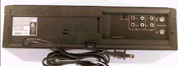
Click to zoom
Application Details
- Equipment Class
- HID - Part 15 TV Interface Device
- Date of Grant
- Jan 05, 1999
- Application Purpose
- Original Equipment
- Date of Application
- Nov 05, 1998
- Equipment Note
- TV INTERFACE DEVICE-VCR
- Frequency Range
- 60.00000000 - 72.00000000
- Company
- LG Electronics USA, Inc.
- Country
- United States
Documents & Files
Document Text
Text extracted from the exhibit documents filed with the FCC. Open a document above to read the original.
Users Manual
1. Read Instructions Read all of the safety and operating instructions before operating the product. 2. Retain Instructions Keep all safety and operating instructions for future reference. 3. Heed Warnings Follow warnings on the product and in the operating guide. 4. Follow Instructions Follow all operating and use instructions. 5. Cleaning Unplug this product from the wall outlet before cleaning.Do not use liquid cleaners or aerosol cleaners. Use adamp cloth for cleaning. 6. Attachments Do not use attachments not recommended by product manufacturer as they may cause hazards. 7. Water and Moisture Do not use this product near water—for example, neara bathtub, wash bowl, sink, or laundry tub, in a wet basement, or near a swimming pool. 8. Accessories Do not place product on an unstable cart, stand,tripod, bracket, or table. Product may fall, causing serious injury to a child or adult, and serious damage tothe product. Use only with a cart, stand, tripod, bracket, or table recommended by the manufacturer or sold withthe product. Any mounting of product should follow manufacturer’s instructions and should use amounting accessory recommended by manufacturer. 9. Transporting Product Move product and cartcombinations with care. Quickstops, excessive force, and unevensurfaces may cause product andcart combination to overturn. 10. Ventilation Slots and openings in cabinet must not be blocked or covered. They are provided for ventilation, to ensure reliable operation, and to protect from overheating.Never block openings by placing product on a bed, sofa, rug, or other similar surface. Do not place product in built-in installation such as a bookcase or rack unless proper ventilation is provided or manufacturer’s instructions have been adhered to. 11. Power Sources Operate product only from type of power source indicated on marking label. If you are not sure of the type of power supply to your home, consult your product dealer or local power company. For products intended to operatefrom battery power or other sources, refer to manual. 12. Line-Cord Polarization Product is equipped with a polarized alternating-currentline plug (a plug having one blade wider than the other).As a safety feature, this plug will fit into power outlet only one way. If you’re unable to insert plug fully into outlet, try reversing the plug. If plug still fails to fit, contact an electrician to replace your obsolete outlet. Do not defeat safety purpose of polarized plug. 13. Power-Cord Protection Route power-supply cords so theyare not likely to be walked on or pinched by items placed upon or against them, paying particularattention to cords at plugs,convenience receptacles, and thepoint where they exit from product. 14. Outdoor Antenna Grounding If an outside antenna or cable system is connected to thisproduct, be sure antenna or cable system is grounded so asto provide some protection against voltage surges and built-up static charges. Article 810 of the National Electrical Code (USA), ANSI/NFPA 70 provides information ongrounding of mast and supporting structure, grounding of lead-in wire to an antenna discharge unit connection togrounding electrodes, and requirements for groundingelectrode. ( See Fig. 1 on reverse side. ) thanks for choosing zenith These simple precautions willhelp ensure that you get manyyears of safe enjoyment from your new product. ZENITH ELECTRONICS1000 MILWAUKEE AVENUEGLENVIEW, IL 60025-2495 safety tips IMPORTANT SAFETY INSTRUCTIONS IMPORTANT SAFETY INSTRUCTIONS IMPORTANT SAFETY INSTRUCTIONS IMPORTANT SAFETY INSTRUCTIONS IMPORTANT SAFETY INSTRUCTIONS IMPORTANT SAFETY INSTRUCTIONS 15. Lightning For added protection forthis product during alightning storm, or whenproduct is left unattendedand unused for longperiods of time, unplug itfrom the wall outlet anddisconnect antenna orcable system.This will prevent damage toproduct due to lightningand power line surges. 16. Power Lines An outside antenna system should not be located in the vicinity of overhead power lines or other electric light or power circuits, or where it can fall into suchpower lines or circuits. When installing an outsideantenna system, take extreme care to keep fromtouching such power lines or circuits, as contact withthem might be fatal. 17. Overloading Do not overload wall outlets, extension cords orintegral convenience receptacles, as this can result inrisk of fire or electric shoc k. 18. Object and Liquid Entry Never push objects of any kind into this product through openings, as they may touch dangerous voltage points or short-out parts that could result in fire or electric shock. Never spill liquid of any kind on product. 19. Servicing Do not attempt to service this product yourself, as opening or removing covers may expose you to dangerous voltage or other hazards. Refer all servicingto qualified service personnel. 20. Wall or Ceiling Mounting Mount product to wall or ceiling only as recommendedby manufacturer. 21. Replacement Parts When replacement part(s) are required, be sure service technician has used replacement part(s) specifiedby manufacturer or have same characteristics as original part(s). Unauthorized substitutions may result infire, electric shock, or other hazards. 22. Damage Requiring Service Unplug this product from the wall outlet and referservicing to qualified service personnel underthese conditions:a. If power-supply cord or plug is damaged. b. If liquid has been spilled or objects have fallen into product. c. If product has been exposed to rain or water. d. If product doesn’t operate normally by following handbook instructions. Adjust only those controls covered by handbook instructions; improper adjustment of othercontrols may result in damage and oftenrequires extensive work by a qualified technician to restore product to normaloperation. e. If product has been dropped or cabinet hasbeen damaged. f. If product exhibits a distinct change in performance. 23. Heat Keep product away from heat sources such as r…
Text truncated - open the document above for the full version.
Block Diagram
2. Power(SMPS) Block Diagram (ALGB420) 5.3VA TO SYS HOT CIRCUIT BD101 R102 C111 Q111 R106 C103 C104 HOT GND F101 V101 R101 BK WH PW101 AC120V R109 R103 4 7 8 9 6 5 10 2 1 4 3 11 12 1 2 IC102 IC103 3 T101 TRANSFORMER 4 2 3 1 LINE FILTER BLOCK (C101,L101) RECTIFIER & SMOOTHING RECTIFIER & SMOOTHING 9V REG. BLOCK (Q152,R153, C153,C154, ZD152) 12V REG. BLOCK (Q151,R151 C151, ZD151) 5V SWITCHING BLOCK 34V SWITCHING BLOCK RECTIFIER & SMOOTHING (D105, C115 R112) FEED-BACK BLOCK (R116,R117,R118 R119,R120,R121 C114) RECTIFIER & SMOOTHING RECTIFIER & SMOOTHING DRIVE & OVER CURRENT LIMIT BLOCK + FDP OPTION TO SYS TO SYS TO SYS TO SYS TO TU/IF TO Hi-Fi, MPX 12.5VA -29VA FD(-) FD(+) 36V 9V 12V(DRUM) TO SYS, DRUM 5.1V(ANALOG) TO AVCP, Hi-Fi FROM SYS 5.1V(DIGITAL) TO SYS, TU/IF R169 R170 SNUBBER BLOCK (Q112,D102,D103,D104,R105, R107,R108,C107,C108,C109) (D101,R104, C105,C106) (D107, C118, R111) (D109, C120, L104,C121) (D108, C119) VOLTAGE DOWN (D151, D152, D153) (D106, C116, L103,C117) (Q158,R162, R163) (Q159, R166, R167) NOTES : Symbol denotes AC ground. Symbol denotes DC chassis ground. '98.10.20 R10378BA ALGB420's FDP OPTION ! ! ! ! ! ! ! ! ! ! ! 5V SWITCHING BLOCK (Q157,R164, R165) FROM SYS P.CTL "H" ACSS/JUST 3. Tuner/IF Block Diagram (ALGB420) 17 16 15 14 13 12 11 10 9 8 7 6 5 4 3 2 1 1 2 3 SW701 SLIDE TU701 N.C A.OUT 19 18 V.OUT AFT IF N.C 30V N.C REG 5V DATA CLOCK ENABLE N.C REG AGC V.IN CONTROL REG 5V CH S/W A.IN FROM POWER 5.1V(A) FROM POWER 36V TO JACK LINE OUT BUFFER Q701 u-COM 45PIN(F SYS) V. IN u-COM 55PIN(F SYS) VCR 'H' u-COM 90PIN(F SYS) IIC CLOCK u-COM 9PIN(TO SYS) AFT TO AVCP V. OUT AUD. IN FROM AUDIO u-COM 91PIN(F SYS) IIC DATA TO Hi-Fi OUT L TO Hi-Fi SAP OUT TO Hi-Fi OUT R 11 2301 1634 IC803 CAX2104S COMPVCCWSDAASCL 3-303-31 '98.10.20 R10381BA ALGB420's 4. AVCP Block Diagram(ALGB420) 1) PB MODE 2) REC MODE V.H/SW30 (FROM u-COM) V.ENV (TO u-COM) 81 84 PRE-AMP SP CH2 CH2 CH1 86 87 88 89 PRE-AMP SP CH1 PRE-AMP EP CH2 CH2 CH1 91 92 93 94 PRE-AMP EP CH1 7978737163626960 X-tal VCO/OSC Serial Cont Interface 3.579545MHz DATA (FROM u-COM) CLOCK (FROM u-COM) 2fsc (TO u-COM) 585554 35 C-CCD CLOCK Drive Y-CCD MIX AMP SQIELCH CLEAR SYNC 46 44 39 42 52 50 56 + + 51 V.OUT (TO u-COM) D-V SYNC (FROM u-COM) C-SYNC (TO u-COM) 2M LPF TrapFM AGCP.EQG.EQD LIMY LPFCLAMP DO/R DO CLAMP YNR Sharpness CONTROL FBC Video ALC LPF DEMO S LPF Main De-Emph NL De-Emph ACCC LPF VCA L-DETBPFBD APC/ACC DET C.K CCD LPF DELAY CTL Trap fh Trap HIFI Trap Main Conv1 Main Conv2 221413192324262118 NC SYNC SEP LINE1VIDEO IN + TUVIDEO IN + V.H/SW30 (FROM u-COM) 81 REC-AMP SP CH2 CH2SP SP EP EP CH1 86 87 88 89 REC-AMP SP CH1 REC-AMP EP CH2 CH2 CH1 91 92 93 94 REC-AMP EP CH1 737163626958 X-tal VCO/OSC Serial Cont Interface 3.579545MHz DATA (FROM u-COM) CLOCK (FROM u-COM) 2fsc (TO u-COM) 60 35 C-CCD CLOCK Drive Y-CCD 6dB AMP 46 44 39 42 52 56 51 V.OUT (TO u-COM) D-V SYNC (FROM u-COM) TrapHPFLPFNL EmphD.E.VCA ATT -10dB ATT -10dB ATT -10dB CCD LPF C-LPF C-LPF Main Conv2 APC/ACC DET Main Conv1 152022141318232426212928303119 LPF FM MOD f0/DEV Adjst Main Emph FBC ALC L-DET VCA (-4dB) REC Trap MIX ATT B.E C.K f0=1.68M BPFACC SYNC SEP YNR C-SYNC (TO u-COM) LINE2VIDEO IN 50 CLAMPCLAMP Y-LPF LPF AGC DET SQUELCH CLEAR SYNC FBC Video ALC VIDEO AGC ++ + + System System System SystemSystem System System System System SystemSystem System System System SP SP EP EP IC301 HA118217 IC301 HA118217 '98 10. 20 R10379BA ALGB420'S 5. Normal Audio Block Diagram(ALGB420) 1) EE Mode IC301 HA118217 AUDIO OUT IC801 AN3664 IC803 CAX2104S TUNER TU701 11 9 DET NORMALAUDIOOUT N.A.IN N.A.OUT (System) LINE AUDIO(R) IN LINE AUDIO(L) IN F REAR Jack OUT R OUT L COMP SAO Level (L) MOD A.OUT VCA OUTPUT SELECTOR 3738 3532 4 16 11 1 30 2 34 5 41 46 45 A. OUT (R) 2) PB Mode2) REC Mode IC801 AN3664 IC301 HA118217 VCA EQ AMP 45 37 11 41 A. OUT (R) MOD A.OUT DATA CLOCK R/P HEAD N.A.IN EQ OUTPUT SELECTOR 7 8 1 100 2 IC301 HA118217 AUDIO OUT IC801 AN3664 IC803 CAX2104S TUNER TU701 REC AMP 81 11 9 DET NORMALAUDIOOUT REC.AUD.OUT R/PHEAD N.A.IN LINE AUDIO(R) IN (FROM REAR JACK) (FROM REAR JACK) LINE AUDIO(L) IN OUT R OUT L COMP IN S OUT LEVEL( L) MOD A. OUT VCA OUTPUT SELECTOR 3738 3532 4 16 11 1 30 2 34 5 41 46 From u-COM 46 Level (L) 45 A. OUT (R ) '98.10.20 ALGB420'S 6. Hi-Fi Block Diagram (ALGB420) 1) PB MODE 2) REC MODE NORMAL AUDIO IN 19 41 37 PB FM HI-FIHEAD MOD A. OUT R CHBPF FM LIM SW.N.C. PNR AUDIOLIMIT OUTPUTSELECT.R L CHBPF PNR AUDIOLIMIT ENV.DET. 452046 SW.N.C. OUTPUTSELECT.L AMP AMP AMP A. ENV. To JackTo Tu/IF (System) TO u-COM. A. OUT(R) To SystemLevel (L) 5.1V(A) 9V FROM POWER IC801 AN3664 GND 39 42 46 31 FROM IC301(AVCP) PEAKDET PEAKDET IC803 CAX2104S AUDIOLIMITAUDIOLIMIT VCO FMLPF INPUT SELECTOR LINEI A.IN(R) LINEI A.IN(L) OUT(L) 5.1V(A) 9V FROM POWER IC801 AN3664 35 4 31 39 34 15 5 OUT(R) Hi-Fi REC FM EVOL/AGCEVOL/AGC PEAKDET. PEAKDET. VCO FMLPF HI-FIALC FROM REAR JACK SW.N.C 38 NORMAL AUDIO OUT TO IC301(A/V) 42 GND 46 S OUT 32 12 30 Hi-FiHEAD 3-52 3-53 '98.10.20 R10382BA ALGB420'S 7. System Block Diagram (ALGB420) GND MODE S1 MODE S2 MODE S3 MODE S4 MODE S/W TO/FROM AVCP T-UP REEL T-UP END PML01 SUP REEL CST.SW 5.3V SW502 5.3VA 5.3VA S501 R550 LD501 DECK IR LED R553 R555 S503 S504 R556 C538 Q514 Q515 R558 C539 R557 C536 R548 C552 R5C6 R548 R590 R541 R539 MS501 X501 10MHz 32.768KHz OSC OSC X502 M LD + LD 2 1 L/D MOTOR 12V R526 R525 5 6 4 7 8 1 10 Vcc 1 Vcc 2 OUT 1 OUT 2 GND IN 2 IN 1 Vref IC502 C529 ZD501 2 1 2 RESET GND Vcc 3 5.5VA 5.3V 9V IC504 + + C561 C521 C504 + C503 R516 R557 C536 SUP END ES502 R564 C537 R554 C537 R544 OSC R/C PMM01 8 3 RC901 Q510 L506 R518 C518 C519 + C532 C505 TO/FROM DECK ZD502 Q522 Q523 Q524 CV IN 77 76 75 74 1 5 7 4 2 33 49 71 22 41 16 IC501 HD6473977 MODE S1 I-Limit MODE S2 MODE S3 MODE S4 T-UP Sensor T-UP Reel SUP Reel CST IN Vss (A/D) Vss (SERVO) Vss (OSD) Vss (SYSCON) Vcc (SYSCON) Vcc (SERVO) CAP. PWM CTL + CTL - DFG CFG CAP. RVS 'H' CAP. ACCEL DRUM ADJ. V. ENV V.H.SW30 C.Sync DPG D.V.Sync 72 73 OSC2 X1 X2 OSC1 70 69 53 5250 fsc …
Text truncated - open the document above for the full version.
ID Label/Location Info
FCC ID : BEJ9QKE4910 ID LABEL P/N 3850R-M0000 STEREO VIDEO RECORDER MODEL NO. ALGB420 AC120V 60Hz 17W SERV. NO. ALGB420 FCC ID:BEJ9QKE4910 ZENITH ELECTRONICS CORPORATION GLENVIEW, IL 60025 USA MADE IN KOREA ® VIDEO EQUIPMENT E160712 LISTED 368K ® LR58446 1998.10.20 50.5mm, 39.5mm CABLE COMPATIBLE TELEVISION/APPARATUS CANADA GRR PART II. TÉLÉVISEUR CABLOCOMPATIBLE/RGR, PARTIE II, CANADA. U.S. PATENTS 4,002,986; 4,317,227; 4,516,170; 4,598,425. LICENSED UNDER CANADIAN PATENTS 1,120,582; 1,145,032. GY P/N 3850R-M0000 STEREO VIDEO RECORDER MODEL NO. ALGB420 AC120V 60Hz 15W SERV. NO. ALGB420 FCC ID: BEJ9QKE4910 ZENITH ELECTRONICS CORPORATION GLENVIEW, IL 60025 USA MADE IN KOREA ® VIDEO EQUIPMENT E160712 LISTED 368K ® LR58446 1998.10.20 50.5mm, 39.5mm CABLE COMPATIBLE TELEVISION/APPARATUS CANADA GRR PART II. TÉLÉVISEUR CABLOCOMPATIBLE/RGR, PARTIE II, CANADA. U.S. PATENTS 4,002,986; 4,317,227; 4,516,170; 4,598,425. LICENSED UNDER CANADIAN PATENTS 1,120,582; 1,145,032. GY P/N 3850R-M0000 STEREO VIDEO RECORDER MODEL NO. ALGB420 AC120V 60Hz 15W SERV. NO. ALGB420 FCC ID: BEJ9QKE4910 ZENITH ELECTRONICS CORPORATION GLENVIEW, IL 60025 USA MADE IN KOREA ® VIDEO EQUIPMENT E160712 LISTED 368K ® LR58446 1998.10.20 50.5mm, 39.5mm CABLE COMPATIBLE TELEVISION/APPARATUS CANADA GRR PART II. TÉLÉVISEUR CABLOCOMPATIBLE/RGR, PARTIE II, CANADA. U.S. PATENTS 4,002,986; 4,317,227; 4,516,170; 4,598,425. LICENSED UNDER CANADIAN PATENTS 1,120,582; 1,145,032. GY
Contact Information
Applicant
David Kim(Team leader, LGEUS NA Policy & Regulatory Affairs)
Technical Contact
LG ELECTRONICS, INCKYEOMSOON KIM
[email protected]847-692-4500
6133 NORTH RIVER ROAD, SUITE 1100 · Rosemont, Illinois · United States
Non-Technical Contact
LG ELECTRONICS, INCKYEOMSOON KIM
[email protected]847-692-4500
Technical Specifications
| # | Rule Parts | Frequency Range | Power Output |
|---|---|---|---|
| 1 | 15B | 60 MHz - 72 MHz | - |
Other Applications from LG Electronics USA, Inc.

BEJTFHOBINI1F1
Jan 08, 2025Telematics
Equipment Class
DTS - Digital Transmission SystemBEJNT-16Z90TS
Oct 02, 2024Notebook Computer
Equipment Class
DSS - Part 15 Spread Spectrum TransmitterBEJSP-PEW8
Sep 26, 2024Stylus Pen
Equipment Class
DCD - Part 15 Low Power Transmitter Below 1705 kHzBEJ-RSMV2
Sep 24, 2024RF Module
Equipment Class
FDS - Part 15 Field Disturbance SensorBEJTFBMEIBN3EU
Sep 24, 2024Telematics
Equipment Class
NII - Unlicensed National Information Infrastructure TX