BEJ9SD751TVDAWIRELESS MOTION SENSOR
LG Electronics USA, Inc.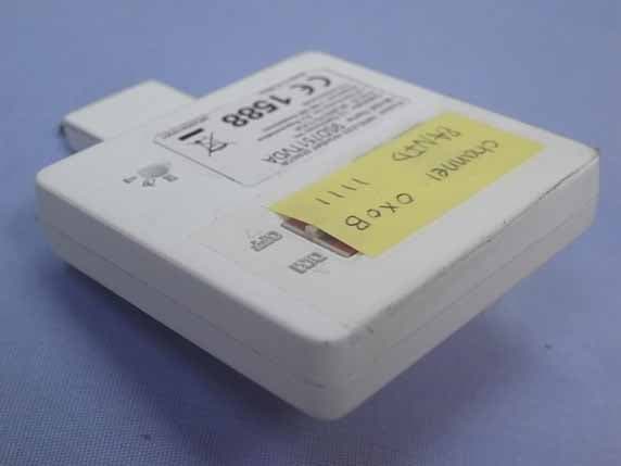
Click to zoom
Application Details
- Equipment Class
- DTS - Digital Transmission System
- Date of Grant
- May 19, 2014
- Application Purpose
- Original Equipment
- Date of Application
- May 17, 2014
- Equipment Note
- WIRELESS MOTION SENSOR
- Frequency Range
- 2405.00000000 - 2480.00000000
- Company
- LG Electronics USA, Inc.
- Country
- United States
Documents & Files
Document Text
Text extracted from the exhibit documents filed with the FCC. Open a document above to read the original.
Users Manual
MFL68488801 Please read this manual carefully before using the product. 1. When this crossed-out wheeled bin symbol is attached to a product it means the product is covered by the European Directive 2002/96/EC. 2. All electrical and electronic products shall be disposed of separately from the municipal waste stream via designated collection facilities appointed by the government or the local authorities. 3. The correct disposal of your old appliance will help prevent potential negative consequences for the environment and human health. 4. For more detailed information about disposal of your old appliance, please contact your city office, waste disposal service or the shop where you purchased the product. ※ Check out below address for more information. 9SD751TVDA WIRELESS HIGHBAY SENSOR OWNER’S MANUAL Specifications Disposal of your old appliance Model9SD751TVDA Sensor Frequency Wireless range Operating conditions Temperature Humidity Weight Dimensions (WHD) installation height Operating voltage Current consumption FCC ID Passive Infrared(PIR) Sensor 2405~2480 MHz, 16 ch Line of sight 98 ft (30 m) For Indoor use only Operating : -4 to 122°F (-20 to 50°C) Storage : -22 to 185°F (-30 to 80°C) 0 to 85 % Rh 1.1 oz (30 g) 2.6” x 2.1” x 1.0” (75 mm x 54 mm x 25 mm) Typical 20 ft (6 m), up to 40 ft (13 m) 3.3 V DC (from LG LED lighting) Max.80 mA BEJ9SD751TVDA http://www.lg.com/global/sustainability/environment/ DimensionsSafety Precautions Features - 1 -- 2 - 54 mm 17 mm 54 mm 75 mm 25 mm 11 mm - Wireless Highbay sensor detects motion and control LG LED Highbay efficiently. Simple installation just by pluging a sensor Easy adjustment using a rotary dial and a switch Wireless communication at 2.4 GHz Possible to be used for LG Lighting control system. Applications High ceiling spaces Like Warehouse, Storage areas, etc. WARNING Violation of warnings may lead to serious injury or death. CAUTION Violation of precautions may lead to light injury or product damage. • Turn power off before install the product. • Do not wipe the surface with inflammables such as alcohol, benzene and acetone. • Do not disassemble the product. • Turn power off before install the product. • Do not install nearby inflammable material • Do not install in areas that have risks of flooding Do not store in a humid area. • Do not install nearby air conditioners and heaters. - 5 -- 6 - InstallationLED operation Adjustment • Delay time : occupancy • initialized button • Dimming level : non-occupancy It is possible to change a delay time from 30 sec to 20 min with the rotary dial. (default : 10 min) Press the button over 5 seconds. If RED LED flashes rapidly for 3 seconds, it is initialized It is possible to choose non -occupancy dimming level, OFF or DIM (default : OFF state) If you choose DIM, LG LED Lighting is dim when there is nobody. If you want to use it for larger areas than one detect area, install multiple sensors and set wireless connection. For further details, see xx page and contact the dealer that you purchased this product. Avoid metal and reinforced concrete walls etc, among sensors if you want to use it for LG Lighting control system. You have to plug the sensor completely. WARNING - 3 -- 4 - Plug the sensor to interface port on compatible LG LED lighting.Flashes once : occupancy detection Flashes twice : occupancy detection while Lighting System interworking Mode Flashes four times : setting completion by wireless setting tool On for 30 seconds after power-up : stability time Rapid flashes for 3 seconds : initialized Rapid flashes continuously : It is connected to non-compatible LG LED Lighting so it cannot work normally Very rapid flashed for 2 seconds : it is hold state about manual setting and network connection state. Troubleshooting It is probably not detect motion. It is not flashes RED LED. • Check the settings by wireless setting tool. It is possible to select RED LED OFF. • Check the detection area. • Make sure installation state. you have to plug the sensor completely. • On specific operating temperature from 90°F(32°C) to 104°F(40°C), It may not detect motion. Lighting is not OFF although nobody is occupancy. • Make sure installation state. you have to plug the sensor completely. • Check the delay time and dimming level non-occupancy. If delay times is too long or diming level is DIM state, lighting may be not OFF. Motion detection is strange. It detects motion abnormally. • Check the installation environment. If there are air conditioner or heater, it should works abnormally. • Check the installation state. LED lighting plugged with sensor have to fix on ceiling and not shake. Detection Area installation height : typical 20 ft (6 m), up to 40 ft (13 m) • Side view • Federal Communications Commission (FCC) Statement diameter 40 ft (12.2 m) diameter 20 ft (6.1 m) 0m 3 6.1 9.1 12.2 6.1 20 0m 0ft 6.1 20 0ft 10 20 30 40 You are cautioned that changes or modifications not expressly approved by the part responsible for compliance could void the user’s authority to operate the equipment. This equipment has been tested and found to comply with the limits for a Class B digital device, pursuant to part 15 of the FCC rules. These limits are designed to provide reasonable protection against harmful interference in a residential installation. This equipment generates, uses and can radiate radio frequency energy and, if not installed and used in accordance with the instructions, may cause harmful interference to radio communications. However, there is no guarantee that interference will not occur in a particular installation. If this equipment does cause harmful interference to radio or television reception, which can be determined by turning the equipment off and on, the user is encouraged to try to correct the interference by one or more of the following measures: - Reorient or relocate the receiving antenna. - Increase the separation between the equipment and receiver. - Connect the equipment into an outlet on a…
Text truncated - open the document above for the full version.
Cover Letter(s)
Authority to Act as Agent Date: 2014. 05. 15 American Certification Body, Inc. 6731 Whittier Avenue Suite C110 McLean, VA 22101 To Whom It May Concern: _____AUDIX Technology Corporation______ is authorized to act on our behalf, until otherwise notified, for applications to American Certification Body, Inc. (ACB). We certify that we are not subject to denial of federal benefits, that includes FCC benefits, pursuant to Section 5301 of the Anti-Drug Abuse Act of 1988, 21 U.S.C. 862. Further, no party, as defined in 47 CFR 1.2002 (b), to the application is subject to denial of federal benefits, that includes FCC benefits. Thank you, Agency Agreement Expiration Date: _____2015. 05. 15 _____ By: __________________________ __ Jacob Cho______ (Signature) (Print name) Title: _______Manager ______________ On behalf of: ___LG Electronics USA ________ (Company Name) Telephone: _____1-201-266-2420 ____________
Cover Letter(s)
Request for Confidentiality Date: 2014. 05. 15 Federal Communications Commission Authorization and Evaluation Division Subject: Confidentiality Request regarding Application for certification of FCC ID: BEJ9SD751TVDA Gentlemen: Pursuant to Section 0.457 and 0.459 of the Commission’s Rules, we hereby request confidential treatment of information accompanying this application as outlined below: Functional Block Diagram Operational Description (theory of operation) Schematic Diagram The above materials contain trade secrets and proprietary information not customarily released to the public. The public disclosure of these materials may be harmful to the applicant and provide unjustified benefits to its competitors. The Applicant understands that pursuant to Section 0.457 of the Rules, disclosure of this application and all accompanying documentation will not be made before the date of the Grant for this application. Sincerely, _______________________________________ Jacob Cho Manager LG Electronics USA
External Photos
LG Electronics Inc. WIRELESS HIGHBAY SENSOR FCC ID. : BEJ9SD751TVDA EUT External Photos Figure 1 General Appearance (Front View) Figure 2 General Appearance (Back View)
ID Label/Location Info
LG Electronics Inc. WIRELESS HIGHBAY SENSOR FCC ID. : BEJ9SD751TVDA FCC ID Label Location z Label Placement Location z FCC ID Label Format FCC ID Label Placement Location
Internal Photos
LG Electronics Inc. WIRELESS HIGHBAY SENSOR FCC ID. : BEJ9SD751TVDA EUT Internal Photos Figure 3 Internal View (Main Board, Front View ) Figure 4 Internal View (Main Board, Back View)
RF Exposure Info
Maximum Permissive Exposure FCC ID: BEJ9SD751TVDA Product Name: WIRELESS HIGHBAY SENSOR Model No: 9SD751TVDA 1. According to FCC CFR 47 §1.1310, the criteria listed in the following table shall be used to evaluate the environmental impact of human exposure to radio frequency (RF) radiation as specified in 1.1307(b). Table 1 Limits for Maximum Permissible Exposure 2. MPE Calculation LG Electronics Inc. declares that the product described above has been evaluated and found to comply with the RF exposure limits for humans, as specified based on ANSI/FCC recommendation. Based on safety distance 20cm, the antenna gain is 0.9073 dBi, and the power output is 6.561mW, the power density is 0.0016mW/cm 2 RF Exposure Calculations: S = (P * G) / (4* * r^2) or r = (P * G) / (4 * * S) Where S = Power Density in mW/cm^2 P=8.17dBm=6.561mw G =0.9073 dBi=1.232 Numerical r = 20cm S = 6.561*1.232/ 4** 20^2=0.0016 mW/cm 2 Sincerely Yours, ____________________________________ Mr. Ben Cheng Manager AUDIX Technology Corporation
Test Report
FCC ID: BEJ9SD751TVDA Page 1 of 50 AUDIX Technology Corporation Report No. EM-F140293 APPLICATION FOR CERTIFICATION On Behalf of LG Electronics Inc. WIRELESS HIGHBAY SENSOR Model No.: 9SD751TVDA FCC ID: BEJ9SD751TVDA Brand: LG Prepared for : LG Electronics Inc. San4-1, Nakseongdea-dong, Gwanak-gu, Seoul 151-919, Korea Prepared by : AUDIX Technology Corporation EMC Department No. 53-11, Dingfu, Linkou Dist., New Taipei City 244, Taiwan, R.O.C. Tel : (02) 2609-9301, 2609-2133 Fax: (02) 2609-9303 File Number : C1M1405061 Report Number : EM-F140293 Date of Test : 2014. 05. 13 ~ 16 Date of Report : 2014. 05. 16 FCC ID: BEJ9SD751TVDA Page 2 of 50 AUDIX Technology Corporation Report No. EM-F140293 TABLE OF CONTENTS Description Page TEST REPORT CERTIFICATION ..............................................................................................4 1. DESCRIPTION OF REVISION HISTORY .......................................................................... 5 2. GENERAL INFORMATION .................................................................................................. 6 2.1. Description of Device (EUT)........................................................................................................... 6 2.2. Antenna Information........................................................................................................................ 6 2.3. Tested Supporting System Details ................................................................................................... 7 2.4. Description of Test Facility ............................................................................................................. 7 2.5. Measurement Uncertainty................................................................................................................ 8 3. CONDUCTED EMISSION MEASUREMET........................................................................ 9 3.1. Test Equipment ................................................................................................................................ 9 3.2. Block Diagram of Test Setup........................................................................................................... 9 3.3. Powerline Conducted Emission Limit [§15.207, Class B] .............................................................. 9 3.4. Operating Condition of EUT ......................................................................................................... 10 3.5. Test Procedure ............................................................................................................................... 10 3.6. Conducted Emission Measurement Results................................................................................... 10 4. RADIATED EMISSION MEASUREMENT ....................................................................... 13 4.1. Test Equipment .............................................................................................................................. 13 4.2. Test Setup ...................................................................................................................................... 13 4.3. Radiated Emission Limits (§15.209) .............................................................................................15 4.4. Operating Condition of EUT ......................................................................................................... 15 4.5. Test Procedure ............................................................................................................................... 16 4.6. Test Results.................................................................................................................................... 17 5. 6dB BANDWIDTH MEASUREMENT ................................................................................ 26 5.1. Test Equipment .............................................................................................................................. 26 5.2. Block Diagram of Test Setup......................................................................................................... 26 5.3. Specification Limits [§15.247(a)(2)] ............................................................................................. 26 5.4. Operating Condition of EUT ......................................................................................................... 26 5.5. Test Procedure ............................................................................................................................... 26 5.6. Test Results.................................................................................................................................... 27 6. MAXIMUM PEAK OUTPUT POWER MEASUREMENT .............................................. 29 6.1. Test Equipment .............................................................................................................................. 29 6.2. Block Diagram of Test Setup......................................................................................................... 29 6.3. Specification Limits [§15.247(b)-(3)]............................................................................................ 29 6.4. Operating Condition of EUT ......................................................................................................... 29 6.5. Test Procedure ............................................................................................................................... 29 6.6. Test Results.................................................................................................................................... 30 7. EMISSION LIMITATIONS MEASUREMENT ................................................................. 31 7.1. Test Equipment .............................................................................................................................. 31 7.2. Block Diagram of Test Setup..........…
Text truncated - open the document above for the full version.
Test Setup Photos
FCC ID: BEJ9SD751TVDA Page 45 of 46 AUDIX Technology Corporation Report No. EM-F140293 12. PHOTOGRAPHS 12.1. Photos of Radiated Measurement at Semi-Anechoic Chamber 12.1.1. Frequency Below 1GHz 12.1.2. Frequency Above 1GHz FCC ID: BEJ9SD751TVDA Page 46 of 46 AUDIX Technology Corporation Report No. EM-F140293 12.2. Photo of Section RF Conducted Measurement
Contact Information
Applicant
David Kim(Team leader, LGEUS NA Policy & Regulatory Affairs)
Technical Contact
AUDIX Technology CorporationBen Chang
[email protected]886 2609-9301
No. 53-11, Dingfu, Linkou Dist. · New Taipei City · Taiwan
Non-Technical Contact
AUDIX Technology CorporationJarwei Wang
[email protected]886 2609-9301
Test Firm
Audix Technology CorporationLeon Liu
Technical Specifications
| # | Rule Parts | Frequency Range | Power Output |
|---|---|---|---|
| 1 | 15C | 2.40 GHz - 2.48 GHz | 6.56 mW |
Other Applications from LG Electronics USA, Inc.

BEJTFHOBINI1F1
Jan 08, 2025Telematics
Equipment Class
DTS - Digital Transmission SystemBEJNT-16Z90TS
Oct 02, 2024Notebook Computer
Equipment Class
DSS - Part 15 Spread Spectrum TransmitterBEJSP-PEW8
Sep 26, 2024Stylus Pen
Equipment Class
DCD - Part 15 Low Power Transmitter Below 1705 kHzBEJ-RSMV2
Sep 24, 2024RF Module
Equipment Class
FDS - Part 15 Field Disturbance SensorBEJTFBMEIBN3EU
Sep 24, 2024Telematics
Equipment Class
NII - Unlicensed National Information Infrastructure TX