BEJAX5000Tri-Mode Dual-Band Analog/PCS Phone (AMPS/CDMA)
LG Electronics USA, Inc.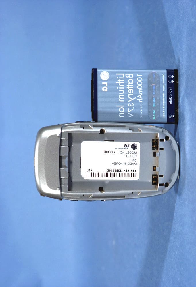
Click to zoom
Application Details
- Equipment Class
- PCE - PCS Licensed Transmitter held to ear
- Date of Grant
- Oct 05, 2004
- Application Purpose
- Original Equipment
- Date of Application
- Oct 05, 2004
- Equipment Note
- Tri-Mode Dual-Band Analog/PCS Phone (AMPS/CDMA)
- Frequency Range
- 1851.25000000 - 1908.75000000
- Company
- LG Electronics USA, Inc.
- Country
- United States
Documents & Files
Document Text
Text extracted from the exhibit documents filed with the FCC. Open a document above to read the original.
Users Manual
- 1 - AX5000 User’s Manual Sep. 13, 2004 - 2 - LIMITED WARRANTY STATEMENT 1. WHAT THIS WARRANTY COVERS: LG offers you a limited warranty that the enclosed subscriber unit and its enclosed accessories will be free from defects in material and workmanship, according to the following terms and conditions: (1) The limited warranty for the product extends for ONE (1) year beginning on the data of purchase of the product. (2) The limited warranty extends on to the original purchaser of the product and is not assignable or transferable to any subsequent purchaser/end user. (3) This warranty is good only to the original purchaser of the product during the warranty period as long as it is in the U.S., including Alaska, Hawaii, U.S. Territories and Canada. (4) The external housing and cosmetic parts shall not be covered under these limited warranty terms. (5) Upon request from LG, the consumer must provide information to reasonably prove the date of purchase. (6) The customer shall bear the cost of shipping the product to the Customer Service Department of LG. LG shall bear the cost of shipping the product back to the consumer after the completion of service under this limited warranty. 2. WHAT THIS WARRANTY DOES NOT COVER: (1) Defects or damages resulting from use of the product in other than its normal and customary manner. (2) Defects or damages from abnormal use, abnormal conditions, improper storage, exposure to moisture or dampness, unauthorized modifications, unauthorized connections, unauthorized repair, misuse, neglect, abuse, accident, alteration, improper installation, or other acts which are not the fault of LG, including damage caused by shipping blown fuses spills of food or liquid. (3) Breakage or damage to antennas unless caused directly by defects in material or workmanship. (4) That the Customer Service Department at LG was net notified by consumer of the alleged defect or malfunction of the product during the applicable limited warranty period. (5) Products which have had the serial number removed or made illegible. (6) The limited warranty is in lieu of all other warranties, express or implied either in fact or by operations law, statutory or otherwise, including, but limited to any implied warranty of marketability or fitness for a particular use. (7) Damage resulting from use of non-LG approved accessories. (8) All plastic surfaces and all other externally exposed parts that are scratched or damaged due to normal customer use. (9) Products operated outside published maximum ratings. - 3 - (10) Products used or obtained in a rental program. (11) Consumables (such as fuses). 3. STATE LAW RIGHTS: No other express warranty is applicable to this product. THE DURATION OF ANY IMPLIED WARRANTIES, INCLUDING THE IMPLIED WARRANTY OF MARKETABILITY, IS LIMITED TO THE DURATION OF THE EXPRESS WARRANTY HEREIN. LG INFOCOMM INC. SHALL NOT BE LIABLE FOR THE LOSS OF THE USE OF THE PRODUCT, INCONVENIENCE, LOSS OR ANY OTHER DAMAGES, DIRECT OR CONSEQUENTIAL, RISING OUT OF THE USE OF, OR INABILITY TO USE, THIS PRODUCT OR FOR ANY BREACH OF ANY EXPRESS OR IMPLIED WARRANTY, INCLUDING THE IMPLIED WARRANTY OF MARKETABILITY APPLICABLE TO THIS PRODUCT. Some states do not allow the exclusive of imitation of incidental or consequential damages or limitations on how long an implied warranty lasts; so these limitations or exclusions may not apply to you. This warranty gives you specific legal rights and you may also have other rights which vary from state to state. 4. HOW TO GET WARRANTY SERVICE: To obtain warranty service, please call the following telephone number from anywhere in the continental United States: LG Infocomm Inc. 201 James Record Road Huntsville, AL 35824 Tel. 1-800-793-8896 Fax. 1-800-448-4026 www.lgeservice.com DO NOT RETURN YOUR PRODUCT TO THE ABOVE ADDRESS. Please call or write for the location of the LGIC authorized service center nearest you and for the procedures for obtaining warranty claims. - 4 - SUBJECT The AX5000 phone has been designed to operate on the latest digital mobile communication technology, Code Division Multiple Access (CDMA). This CDMA digital technology has greatly enhanced voice clarity and can provide a variety of advanced features. Currently, CDMA mobile communication technology has been commercially used in Cellular and Personal Communication Service (PCS). The difference between them is the operating frequency spectrum. Cellular uses 800MHz and PCS uses 1.9GHz. The AX5000 can operate on 1.9GHz or 800 MHz frequency, we usually call it dual-band phone. Also, AX5000 works on Advanced Mobile Phone Service (AMPS). We call it Tri -mode phone. This phone is the one of tri band Quad mode - 800Mhz CDMA, 1900Mhz PCS, 1500Mhz GPS. The CDMA technology adopts DSSS (Direct Sequence Spread Spectrum). This feature of DSSS enables the phone to keep communication from being crossed and to use one frequency channel by multiple users in the same specific area, resulting that it increases the capacity 10 times more compared with that in the analog mode currently used. Soft/Softer Handoff, Hard Handoff, and Dynamic RF power Control technologies are combined into this phone to reduce the call being interrupted in a middle of talking over the phone. Cellular and PCS CDMA network consists of MSO (Mobile Switching Office), BSC (Base Station Controller), BTS (Base station Transmission System), and MS (Mobile Station). The following table lists some major CDMA Standards. CDMA Standard Designator Description Basic air interface TIA/EIA-95A TSB-74 ANSI J-STD-008 TIA/EIA-IS2000 CDMA Dual-Mode Air Interface 14.4kbps radio link protocol and inter-band operations IS-95 adapted for PCS frequency band cdma2000 1xRTT Air Interface Network TIA/EIA/IS-634 TIA/EIA/IS/651 TIA/EIA/IS-41-C TIA/EIA/IS-124 MAS-BS PCSC-RS Intersystem operations Nom-signaling data comm. Service TIA/EIA/IS-96-B TIA/EIA/IS-99 TIA/EIA/IS-637 TIA/EIA/IS-657 IS-801 Speech CODEC Assign data and fax Short message service Packet data…
Text truncated - open the document above for the full version.
Attestation Statements
September 13. 2004 Federal Communication Commission Equipment Authorization Branch 7435 Oakland Mills Road Columbia, MD 21046 In re : LG Electronics Inc.. Tri-band Quad-mode CDMA Phone (Amps/Cellular/PCS/GPS) Part 22, 24 Certification Request for Confidentiality Gentlemen: In accordance with 0.459 of CFR 47, LG Electronics, Inc. hereby requests confidentiality of the Block Diagrams attachment, Schematic Diagrams & Circuit Description attachment, Operational Description attachment, and Parts List/Tune-Up Procedure attachment for the above-referenced Type Acceptance application. These documents contain detailed system and equipment description and related information about the product which LG Electronics Inc. Considers to be proprietary, confidential, and a custom design and, otherwise, would not release to the general public. Since this design is a basis from which future technological products will evolve, LG Electronics Inc. considers this information to be of benefit to its competitors, such that the disclosure of the information in these documents would give competitors an unfair advantage in the market. Sincerely, E.S.Park Chief Research Engineer CDMA Handset Lab LG Electronics Inc. Tel : 82-2-850-3850 Fax : 82-2-850-3861 [email protected] 459-9, Kasan-dong,Kemchun-ku Seoul 153-023, Korea LG Electronics Inc. LGE Tel : 82-2-850-3850 Fax : 82-2-850-3861 [email protected] 459-9, Kasan-dong,Kemchun-ku Seoul 153-023, Korea LG Electronics Inc. LGE September 13. 2004 Federal Communication Commission Equipment Authorization Branch 7435 Oakland Mills Road Columbia, MD 21046 Subject : LG Electronics Inc.. FCC ID: BEJAX5000 User’ s Manual RF Exposure Warning Statement Gentlemen: LG Electronics, Inc. hereby conforms that the attached RF exposure warning page will be ready visible to the user, and will be placed at a prominent location in the front of user’ s manual. If you have any questions or comments concerned the above, please do not hesitate to contact PCTEST Lab. or me at (410)290-6652 Sincerely, E.S.Park Chief Research Engineer CDMA Handset Lab LG Electronics Inc.
Cover Letter(s)
October 4, 2004 Federal Communications Commission Equipment Approval Services 7435 Oakland Mills Road Columbia, MD 21046 SUBJECT: LG ELECTRONICS, INC. FCC ID: BEJAX5000 Part 22/24 Certification Gentlemen: Submitted herewith, on behalf of LG ELECTRONICS, INC., is an application for Part 22/24 Certification of the Tri-Mode Dual-Band Analog/PCS CDMA Phone (AMPS/CDMA). Attached is the applicant’s Letter of Authorization, Confidentiality Request, measurement report test data and plots, RF Exposure measurement report and data, FCC ID label and location, test setup photographs, internal and external photographs, block diagram (confidential), circuit diagrams & description (confidential), operational description (confidential), parts list & tune-up procedure (confidential), and the user's manual. Should you have any questions or comments concerning the above, please contact the undersigned. cc: LG ELECTRONICS, INC.
External Photos
LGE FCC ID: BEJAX5000 EUT Photographs © 2004 PCTEST Lab. Tri-Mode Dual-Band Analog/PCS Phone Model: AX5000 LGE FCC ID: BEJAX5000 EUT Photographs © 2004 PCTEST Lab. Tri-Mode Dual-Band Analog/PCS Phone Model: AX5000 LGE FCC ID: BEJAX5000 EUT Photographs © 2004 PCTEST Lab. Tri-Mode Dual-Band Analog/PCS Phone Model: AX5000 LGE FCC ID: BEJAX5000 EUT Photographs © 2004 PCTEST Lab. Tri-Mode Dual-Band Analog/PCS Phone Model: AX5000 LGE FCC ID: BEJAX5000 EUT Photographs © 2004 PCTEST Lab. Tri-Mode Dual-Band Analog/PCS Phone Model: AX5000 LGE FCC ID: BEJAX5000 EUT Photographs © 2004 PCTEST Lab. Tri-Mode Dual-Band Analog/PCS Phone Model: AX5000 LGE FCC ID: BEJAX5000 EUT Photographs © 2004 PCTEST Lab. Tri-Mode Dual-Band Analog/PCS Phone Model: AX5000
ID Label/Location Info
© 2004 PCTEST Lab FCC ID SAMPLE LABEL & LOCATION LABELLING REQUIREMENTS The Label shown shall be permanently affixed at a conspicuous location on the device and be readily visible to the user at the time of purchase. (SEE NEXT PAGE) LG Electronics Inc. 10 04-10-1 2. 983 (f) Equipment Identification: LG Electronics Inc. LGE Model No. : AX5000 FCC ID : BEJAX5000 S/N : Made in Korea
Internal Photos
LGE FCC ID: BEJAX5000 EUT Photographs © 2004 PCTEST Lab. Tri-Mode Dual-Band Analog/PCS Phone Model: AX5000 LGE FCC ID: BEJAX5000 EUT Photographs © 2004 PCTEST Lab. Tri-Mode Dual-Band Analog/PCS Phone Model: AX5000 LGE FCC ID: BEJAX5000 EUT Photographs © 2004 PCTEST Lab. Tri-Mode Dual-Band Analog/PCS Phone Model: AX5000 LGE FCC ID: BEJAX5000 EUT Photographs © 2004 PCTEST Lab. Tri-Mode Dual-Band Analog/PCS Phone Model: AX5000 LGE FCC ID: BEJAX5000 EUT Photographs © 2004 PCTEST Lab. Tri-Mode Dual-Band Analog/PCS Phone Model: AX5000 LGE FCC ID: BEJAX5000 EUT Photographs © 2004 PCTEST Lab. Tri-Mode Dual-Band Analog/PCS Phone Model: AX5000 LGE FCC ID: BEJAX5000 EUT Photographs © 2004 PCTEST Lab. Tri-Mode Dual-Band Analog/PCS Phone Model: AX5000 LGE FCC ID: BEJAX5000 EUT Photographs © 2004 PCTEST Lab. Tri-Mode Dual-Band Analog/PCS Phone Model: AX5000 LGE FCC ID: BEJAX5000 EUT Photographs © 2004 PCTEST Lab. Tri-Mode Dual-Band Analog/PCS Phone Model: AX5000
RF Exposure Info
PCTEST ENGINEERING LABORATORY, INC. 6660 – B Dobbin Road • Columbia, MD 21045 • USA Telephone 410.290.6652 / Fax 410.290.6654 http://www.pctestlab.com (email: [email protected]) CERTIFICATE OF COMPLIANCE (SAR EVALUATION) PCTEST SAR REPORT SAR Measurement Report Reviewed by: Quality Manager SAR Filename: SAR-240913532.BEJ Test Dates: September 13-15, 2004 Phone Type: Tri-Mode Dual-Band FCC ID: BEJAX5000 Page 1 of 35 © 2004 PCTEST Engineering Laboratory, Inc APPLICANT NAME & ADDRESS: DATE & LOCATION OF TESTING: LG ELECTRONICS, INC. Dates of Tests: September 13-15, 2004 2000 Milbrook Drive Test Report S/N: SAR.240913532.BEJ Lincolnshire, IL 60069 Test Site: PCTEST Lab, Columbia MD FCC ID: BEJAX5000 APPLICANT: LG ELECTRONICS, INC. EUT Type: Tri-Mode Dual-Band Analog/PCS Phone (AMPS/CDMA) Tx Frequency: 824.04 – 848.97 MHz (AMPS) / 824.70 – 848.31 MHz (CDMA) 1851.25 – 1908.75 MHz (PCS CDMA) Rx Frequency: 869.04 – 893.97 MHz (AMPS) / 869.70 – 893.31 MHz (CDMA) 1931.25 – 1988.75 MHz (PCS CDMA) Max. RF Output Power: 0.450 W ERP AMPS (26.529 dBm) / 26.5 dBm Conducted 0.287 W ERP CDMA (24.583 dBm) / 24.5 dBm Conducted 0.335 W EIRP PCS CDMA (25.251 dBm) / 24.5 dBm Conducted Max. SAR Measurement: 1.230 W/kg AMPS Head SAR; 0.848 W/kg AMPS Body SAR; 0.674 W/kg CDMA Head SAR; 0.664 W/kg CDMA Body SAR; 0.382 W/kg PCS CDMA Head SAR; 0.425 W/kg PCS CDMA Body SAR Trade Name/Model(s): AX5000 FCC Classification: Licensed Portable Transmitter Held to Ear (PCE) FCC Rule Part(s): §2.1093; FCC/OET Bulletin 65 Supplement C [July 2001] Application Type: Certification Test Device Serial No.: identical prototype [S/N: #23B00D0B] This wireless portable device has been shown to be capable of compliance for localized specific absorption rate (SAR) for uncontrolled environment/general population exposure limits specified in ANSI/IEEE Std. C95.1-1992 and had been tested in accordance with the measurement procedures specified in FCC/OET Bulletin 65 Supplement C (2001) and IEEE 1528 – 2003. I attest to the accuracy of data. All measurements reported herein were performed by me or were made under my supervision and are correct to the best of my knowledge and belief. I assume full responsibility for the completeness of these measurements and vouch for the qualifications of all persons taking them. Grant Conditions: Power output listed is ERP for Part 22 and EIRP for Part 24. SAR compliance for body- worn operating configuration is based on a separation distance of 1.5 cm between the back of the unit and the body of the user. End-users must be informed of the body-worn operating requirements for satisfying RF exposure compliance. Belt clips or holsters may not contain metallic components. PCTEST certifies that no party to this application has been denied the FCC benefits pursuant to Section 5301 of the Anti-Drug Abuse Act of 1988, 21 U.S.C. 862. PCTEST SAR REPORT SAR Measurement Report Reviewed by: Quality Manager SAR Filename: SAR-240913532.BEJ Test Dates: September 13-15, 2004 Phone Type: Tri-Mode Dual-Band FCC ID: BEJAX5000 Page 2 of 35 © 2004 PCTEST Engineering Laboratory, Inc TABLE OF CONTENTS 1. INTRODUCTION / SAR DEFINITION................................................................................3 2. SAR MEASUREMENT SETUP............................................................................................4 3. DASY4 E-FIELD PROBE SYSTEM.......................................................................................5 4. PROBE CALIBRATION PROCESS......................................................................................6 5. PHANTOM & EQUIVALENT TISSUES................................................................................7 6. TEST SYSTEM SPECIFICATIONS........................................................................................8 7. DOSIMETRIC ASSESSMENT & PHANTOM SPECS...............................................................9 8. DEFINITION OF REFERENCE POINTS.............................................................................10 9. TEST CONFIGURATION POSITIONS..............................................................................11 10. ANSI/IEEE C95.1 - 1992 RF EXPOSURE LIMITS................................................................14 11. MEASUREMENT UNCERTAINTIES..................................................................................15 12. SYSTEM VERIFICATION.................................................................................................16 13. SAR TEST DATA SUMMARY.......................................................................................17-32 15. SAR TEST EQUIPMENT..........................................................................................33 16. CONCLUSION..............................................................................................................33 17. REFERENCES.................................................................................................................35 PCTEST SAR REPORT SAR Measurement Report Reviewed by: Quality Manager SAR Filename: SAR-240913532.BEJ Test Dates: September 13-15, 2004 Phone Type: Tri-Mode Dual-Band FCC ID: BEJAX5000 Page 3 of 35 © 2004 PCTEST Engineering Laboratory, Inc 1. INTRODUCTION / SAR DEFINITION The FCC has adopted the guidelines for evaluating the environmental effects of radiofrequency radiation in ET Docket 93-62 on Aug. 6, 1996 to protect the public and workers from the potential hazards of RF emissions due to FCC-regulated portable devices.[1] The safety limits used for the environmental evaluation measurements are based on the criteria published by the American National Standards Institute (ANSI) for localized specific absorption rate (SAR) in IEEE/ANSI C95.1-1992 Standard for Safety Levels with Respect to Human Exposure to Radio Frequency Electromagnetic Fields, 3 kHz to 300 GHz. (c) 1992 by the Institute of Electrical and Electronics Engineers, Inc., New York, New York 10017.[2] The measurement procedure describe…
Text truncated - open the document above for the full version.
RF Exposure Info
PCTEST ENGINEERING LABORATORY, INC. DUT: AX5000; Type: LGE Tri Mode Phone; Serial: 23B00D0B; Conducted Power: 26.5 dBm Communication System: AMPS; Frequency: 836.49 MHz;Duty Cycle: 1:1 Medium: 835 Brain ( σ = 0.91 mho/m, ε r = 42.70, ρ = 1000 kg/m 3 ) Phantom section: Right Section Test Date: 09-13-2004; Ambient Temp: 23.4°C; Tissue Temp: 21.2°C Probe: ES3DV2 - SN3022; ConvF(6.1, 6.1, 6.1); Calibrated: 9/23/2003 Sensor-Surface: 3mm (Mechanical Surface Detection) Electronics: DAE3 Sn455; Calibrated: 1/6/2004 Phantom: SAM 12b; Type: SAM 4.0; Serial: TP:1197 Measurement SW: DASY4, V4.3 Build 16; Postprocessing SW: SEMCAD, V1.8 Build 123 Touch, Ch.0383 Area Scan (6x14x1): Measurement grid: dx=15mm, dy=15mm Zoom Scan (5x5x7)/Cube 0: Measurement grid: dx=8mm, dy=8mm, dz=5mm Reference Value = 11.4 V/m Peak SAR (extrapolated) = 1.8 W/kg SAR(1 g) = 1.2 mW/g; SAR(10 g) = 0.781 mW/g 0 dB = 1.41mW/g PCTEST ENGINEERING LABORATORY, INC. DUT: AX5000; Type: LGE Tri Mode Phone; Serial: 23B00D0B; Conducted Power: 26.5 dBm Communication System: AMPS; Frequency: 836.49 MHz;Duty Cycle: 1:1 Medium: 835 Brain ( σ = 0.91 mho/m, ε r = 42.70, ρ = 1000 kg/m 3 ) Phantom section: Right Section Test Date: 09 -14-2004; Ambient Temp: 23.5° C; Tissue Temp: 21.4 °C Probe: ES3DV2 - SN3022; ConvF(6.1, 6.1, 6.1); Calibrated: 9/23/2003 Sensor-Surface: 3mm (Mechanical Surface Detection) Electronics: DAE3 Sn455; Calibrated: 1/6/2004 Phantom: SAM 12b; Type: SAM 4.0; Serial: TP:1197 Measurement SW: DASY4, V4.3 Build 16; Postprocessing SW: SEMCAD, V1.8 Build 123 Tilt, Ch.0383 Area Scan (6x14x1): Measurement grid: dx=15mm, dy=15mm Zoom Scan (5x5x7)/Cube 0: Measurement grid: dx=8mm, dy=8mm, dz=5mm Reference Value = 16.3 V/m Peak SAR (extrapolated) = 0.511 W/kg SAR(1 g) = 0.405 mW/g; SAR(10 g) = 0.308 mW/g 0 dB = 0.446mW/g PCTEST ENGINEERING LABORATORY, INC. DUT: AX5000; Type: LGE Tri Mode Phone; Serial: 23B00D0B; Conducted Power: 26.5 dBm Communication System: AMPS; Frequency: 836.49 MHz;Duty Cycle: 1:1 Medium: 835 Brain ( σ = 0.91 mho/m, ε r = 42.70, ρ = 1000 kg/m 3 ) Phantom section: Left Section Test Date: 09-14-2004; Ambient Temp: 23.5°C; Tissue Temp: 21.4°C Probe: ES3DV2 - SN3022; ConvF(6.1, 6.1, 6.1); Calibrated: 9/23/2003 Sensor-Surface: 3mm (Mechanical Surface Detection) Electronics: DAE3 Sn455; Calibrated: 1/6/2004 Phantom: SAM 12b; Type: SAM 4.0; Serial: TP:1197 Measurement SW: DASY4, V4.3 Build 16; Postprocessing SW: SEMCAD, V1.8 Build 123 Touch, Ch.0383 Area Scan (6x14x1): Measurement grid: dx=15mm, dy=15mm Zoom Scan (5x5x7)/Cube 0: Measurement grid: dx=8mm, dy=8mm, dz=5mm Reference Value = 13.3 V/m Peak SAR (extrapolated) = 1.71 W/kg SAR(1 g) = 1.23 mW/g; SAR(10 g) = 0.832 mW/g 0 dB = 1.39mW/g PCTEST ENGINEERING LABORATORY, INC. DUT: AX5000; Type: LGE Tri Mode Phone; Serial: 23B00D0B; Conducted Power: 26.5 dBm Communication System: AMPS; Frequency: 836.49 MHz;Duty Cycle: 1:1 Medium: 835 Brain ( σ = 0.91 mho/m, ε r = 42.70, ρ = 1000 kg/m 3 ) Phantom section: Left Section Test Date: 09-14-2004; Ambient Temp: 23.5°C; Tissue Temp: 21.4°C Probe: ES3DV2 - SN3022; ConvF(6.1, 6.1, 6.1); Calibrated: 9/23/2003 Sensor-Surface: 3mm (Mechanical Surface Detection) Electronics: DAE3 Sn455; Calibrated: 1/6/2004 Phantom: SAM 12b; Type: SAM 4.0; Serial: TP:1197 Measurement SW: DASY4, V4.3 Build 16; Postprocessing SW: SEMCAD, V1.8 Build 123 Tilt, Ch.0383 Area Scan (6x14x1): Measurement grid: dx=15mm, dy=15mm Zoom Scan (5x5x7)/Cube 0: Measurement grid: dx=8mm, dy=8mm, dz=5mm Reference Value = 14.3 V/m Peak SAR (extrapolated) = 0.379 W/kg SAR(1 g) = 0.301 mW/g; SAR(10 g) = 0.228 mW/g 0 dB = 0.332mW/g PCTEST ENGINEERING LABORATORY, INC. DUT: AX5000; Type: LGE Tri Mode Phone; Serial: 23B00D0B; Conducted Power: 24.5 dBm Communication System: Cellular CDMA; Frequency: 836.49 MHz;Duty Cycle: 1:1 Medium: 835 Brain ( σ = 0.91 mho/m, ε r = 42.70, ρ = 1000 kg/m 3 ) Phantom section: Right Section Test Date: 09-14-2004; Ambient Temp: 23.5°C; Tissue Temp: 21.4°C Probe: ES3DV2 - SN3022; ConvF(6.1, 6.1, 6.1); Calibrated: 9/23/2003 Sensor-Surface: 3mm (Mechanical Surface Detection) Electronics: DAE3 Sn455; Calibrated: 1/6/2004 Phantom: SAM 12b; Type: SAM 4.0; Serial: TP:1197 Measurement SW: DASY4, V4.3 Build 16; Postprocessing SW: SEMCAD, V1.8 Build 123 Touch, Ch.0383 Area Scan (6x14x1): Measurement grid: dx=15mm, dy=15mm Zoom Scan (5x5x7)/Cube 0: Measurement grid: dx=8mm, dy=8mm, dz=5mm Reference Value = 8.64 V/m Peak SAR (extrapolated) = 1 W/kg SAR(1 g) = 0.674 mW/g; SAR(10 g) = 0.439 mW/g 0 dB = 0.795mW/g PCTEST ENGINEERING LABORATORY, INC. DUT: AX5000; Type: LGE Tri Mode Phone; Serial: 23B00D0B; Conducted Power: 24.5 dBm Communication System: Cellular CDMA; Frequency: 836.49 MHz;Duty Cycle: 1:1 Medium: 835 Brain ( σ = 0.91 mho/m, ε r = 42.70, ρ = 1000 kg/m 3 ) Phantom section: Right Section Test Date: 09-14-2004; Ambient Temp: 23.5°C; Tissue Temp: 21.4°C Probe: ES3DV2 - SN3022; ConvF(6.1, 6.1, 6.1); Calibrated: 9/23/2003 Sensor-Surface: 3mm (Mechanical Surface Detection) Electronics: DAE3 Sn455; Calibrated: 1/6/2004 Phantom: SAM 12b; Type: SAM 4.0; Serial: TP:1197 Measurement SW: DASY4, V4.3 Build 16; Postprocessing SW: SEMCAD, V1.8 Build 123 Tilt, Ch.0383 Area Scan (6x14x1): Measurement grid: dx=15mm, dy=15mm Zoom Scan (5x5x7)/Cube 0: Measurement grid: dx=8mm, dy=8mm, dz=5mm Reference Value = 10.5 V/m Peak SAR (extrapolated) = 0.206 W/kg SAR(1 g) = 0.162 mW/g; SAR(10 g) = 0.123 mW/g 0 dB = 0.180mW/g PCTEST ENGINEERING LABORATORY, INC. DUT: AX5000; Type: LGE Tri Mode Phone; Serial: 23B00D0B; Conducted Power: 24.5 dBm Communication System: Cellular CDMA; Frequency: 848.31 MHz;Duty Cycle: 1:1 Medium: 835 Brain ( σ = 0.91 mho/m, ε r = 42.70, ρ = 1000 kg/m 3 ) Phantom section: Left Section Test Date: 09-14-2004; Ambient Temp: 23.5°C; Tissue Temp: 21.4°C Probe: ES3DV2 - SN3022; ConvF(6.1, 6.1, 6.1); Calibrated: 9/23/2003 Sensor-Surface: 3mm (Mechanical Surface Detection) Electronics: DAE3 Sn455; Calibrated: 1/6/2004 Phantom: SAM 12b; Type: SAM 4.0; Serial…
Text truncated - open the document above for the full version.
RF Exposure Info
PCTEST ENGINEERING LABORATORY, INC. DUT: Dipole 835 MHz; Type: D835V2; Serial: 406 Communication System: CW; Frequency: 835 MHz;Duty Cycle: 1:1 Medium: 835 Brain ( σ = 0.91 mho/m, ε r = 42.70, ρ = 1000 kg/m 3 ) Phantom section: Flat Section; Space: 1.5 cm Test Date: 09-13-2004; Ambient Temp: 23.4°C; Tissue Temp: 21.2°C Probe: ES3DV2 - SN3022; ConvF(6.1, 6.1, 6.1); Calibrated: 9/23/2003 Sensor-Surface: 3mm (Mechanical Surface Detection) Electronics: DAE3 Sn455; Calibrated: 1/6/2004 Phantom: SAM 12b; Type: SAM 4.0; Serial: TP:1197 Measurement SW: DASY4, V4.3 Build 16; Postprocessing SW: SEMCAD, V1.8 Build 123 835 MHz Dipole Validation Area Scan (7x13x1): Measurement grid: dx=15mm, dy=15mm Zoom Scan (7x7x7)/Cube 0: Measurement grid: dx=5mm, dy=5mm, dz=5mm Input Power = 24.0 dBm (250 mW) SAR(1 g) = 2.48 mW/g; SAR(10 g) = 1.62 mW/g Target SAR(1g) = 2.375 mW/g; Deviation = +4.42 % 0 dB = 2.91mW/g PCTEST ENGINEERING LABORATORY, INC. DUT: Dipole 835 MHz; Type: D835V2; Serial: 406 Communication System: CW; Frequency: 835 MHz;Duty Cycle: 1:1 Medium: 835 Brain ( σ = 0.91 mho/m, ε r = 42.70, ρ = 1000 kg/m 3 ) Phantom section: Flat Section; Space: 1.5 cm Test Date: 09-14-2004; Ambient Temp: 23.5°C; Tissue Temp: 21.4°C Probe: ES3DV2 - SN3022; ConvF(6.1, 6.1, 6.1); Calibrated: 9/23/2003 Sensor-Surface: 3mm (Mechanical Surface Detection) Electronics: DAE3 Sn455; Calibrated: 1/6/2004 Phantom: SAM 12b; Type: SAM 4.0; Serial: TP:1197 Measurement SW: DASY4, V4.3 Build 16; Postprocessing SW: SEMCAD, V1.8 Build 123 835 MHz Dipole Validation Area Scan (7x13x1): Measurement grid: dx=15mm, dy=15mm Zoom Scan (7x7x7)/Cube 0: Measurement grid: dx=5mm, dy=5mm, dz=5mm Input Power = 24.0 dBm (250 mW) SAR(1 g) = 2.33 mW/g; SAR(10 g) = 1.53 mW/g Target SAR(1g) = 2.375 mW/g; Deviation = -1.89 % 0 dB = 2.72mW/g PCTEST ENGINEERING LABORATORY, INC. DUT: Dipole 835 MHz; Type: D835V2; Serial: 406 Communication System: CW; Frequency: 835 MHz;Duty Cycle: 1:1 Medium: 835 Brain ( σ = 0.91 mho/m, ε r = 42.70, ρ = 1000 kg/m 3 ) Phantom section: Flat Section; Space: 1.5 cm Test Date: 09-15-2004; Ambient Temp: 23.5°C; Tissue Temp: 22.1°C Probe: ES3DV2 - SN3022; ConvF(6.1, 6.1, 6.1); Calibrated: 9/23/2003 Sensor-Surface: 3mm (Mechanical Surface Detection) Electronics: DAE3 Sn455; Calibrated: 1/6/2004 Phantom: SAM 12b; Type: SAM 4.0; Serial: TP:1197 Measurement SW: DASY4, V4.3 Build 16; Postprocessing SW: SEMCAD, V1.8 Build 123 835 MHz Dipole Validation Area Scan (7x13x1): Measurement grid: dx=15mm, dy=15mm Zoom Scan (7x7x7)/Cube 0: Measurement grid: dx=5mm, dy=5mm, dz=5mm Input Power = 24.0 dBm (250 mW) SAR(1 g) = 2.56 mW/g; SAR(10 g) = 1.67 mW/g Target SAR(1g) = 2.375 mW/g; Deviation = +7.78 % 0 dB = 3mW/g PCTEST ENGINEERING LABORATORY, INC. DUT: Dipole 1900 MHz; Type: D1900V2; Serial: 502 Communication System: CW; Frequency: 1900 MHz;Duty Cycle: 1:1 Medium: 1900 Brain ( σ = 1.46 mho/m, ε r = 38.80, ρ = 1000 kg/m 3 ) Phantom section: Flat Section; Space: 1.0 cm Test Date: 09-15-2004; Ambient Temp: 23.0°C; Tissue Temp: 22.4°C Probe: ES3DV2 - SN3022; ConvF(5, 5, 5); Calibrated: 9/23/2003 Sensor-Surface: 3mm (Mechanical Surface Detection) Electronics: DAE3 Sn455; Calibrated: 1/6/2004 Phantom: SAM 12b; Type: SAM 4.0; Serial: TP:1197 Measurement SW: DASY4, V4.3 Build 16; Postprocessing SW: SEMCAD, V1.8 Build 123 1900 MHz Dipole Validation Area Scan (6x6x1): Measurement grid: dx=15mm, dy=15mm Zoom Scan (7x7x7)/Cube 0: Measurement grid: dx=5mm, dy=5mm, dz=5mm Input Power = 20.0 dBm (100 mW) SAR(1 g) = 3.81 mW/g; SAR(10 g) = 1.91 mW/g Target SAR(1g) = 3.97 mW/g; Deviation = -4.03 % 0 dB = 4.92mW/g
RF Exposure Info
ES3DV2-SN:3022 Page 1 of 2 December 3, 2003 Additional Conversion Factors for Dosimetric E-Field Probe Type: Serial Number: Place of Assessment: Date of Assessment: Probe Calibration Date: Schmid & Partner Engineering AG hereby certifies that conversion factor(s) of this probe have been evaluated on the date indicated above. The assessment was performed using the FDTD numerical code SEMCAD of Schmid & Partner Engineering AG. Since the evaluation is coupled with measured conversion factors, it has to be recalculated yearly, i.e., following the re-calibration schedule of the probe. The uncertainty of the numerical assessment is based on the extrapolation from measured value at 900 MHz or at 1800 MHz. Assessed by: ES3DV2 3022 Zurich December 3, 2003 September 23, 2003 ES3DV2-SN:3022 Page 2 of 2 December 3, 2003 Dosimetric E-Field Probe ES3DV2 SN:3022 Conversion factor (± standard deviation) 1950 MHz ConvF 4.7 ± 9.5% e r = 40.0 ± 5% s = 1.40 ± 5% mho/m (head tissue) 1950 MHz ConvF 4. 3 ± 9.5% e r = 53.3 ± 5% s = 1.52 ± 5% mho/m (body tissue) ES3DV2-SN:3022Page 1 of 2November 28, 2003 Additional Conversion Factors for Dosimetric E-Field Probe Type: Serial Number: Place of Assessment: Date of Assessment: Probe Calibration Date: Schmid & Partner Engineering AG hereby certifies that conversion factor(s) of this probe have been evaluated on the date indicated above. The assessment was performed using the FDTD numerical code SEMCAD of Schmid & Partner Engineering AG. Since the evaluation is coupled with measured conversion factors, it has to be recalculated yearly, i.e., following the re-calibration schedule of the probe. The uncertainty of the numerical assessment is based on the extrapolation from measured value at 900 MHz or at 1800 MHz. Assessed by: ES3DV2 3022 Zurich November 28, 2003 September 23, 2003 ES3DV2-SN:3022Page 2 of 2November 28, 2003 Dosimetric E-Field Probe ES3DV2 SN:3022 Conversion factor (± standard deviation) 1600 MHzConvF5.2 ± 8% e r =40.3 ± 5% s =1.29 ± 5% mho/m (head tissue) 1600 MHzConvF4.9 ± 8% e r =53.8 ± 5% s =1.40 ± 5% mho/m (body tissue) ES3DV2-SN:3022Page 1 of 2December 9, 2003 Additional Conversion Factors for Dosimetric E-Field Probe Type: Serial Number: Place of Assessment: Date of Assessment: Probe Calibration Date: Schmid & Partner Engineering AG hereby certifies that conversion factor(s) of this probe have been evaluated on the date indicated above. The assessment was performed using the FDTD numerical code SEMCAD of Schmid & Partner Engineering AG. Since the evaluation is coupled with measured conversion factors, it has to be recalculated yearly, i.e., following the re-calibration schedule of the probe. The uncertainty of the numerical assessment is based on the extrapolation from measured value at 900 MHz or at 1800 MHz. Assessed by: ES3DV2 3022 Zurich December 9, 2003 September 23, 2003 ES3DV2-SN:3022Page 2 of 2December 9, 2003 Dosimetric E-Field Probe ES3DV2 SN:3022 Conversion factor (± standard deviation) 2140 MHzConvF4.5 ± 8% e r =39.8 ± 5% s =1.49 ± 5% mho/m (brain tissue)
RF Exposure Info
LGE FCC ID: BEJAX5000 EUT Photographs © 2004 PCTEST Lab. Tri-Mode Dual-Band Analog/PCS Phone Model: AX5000 LGE FCC ID: BEJAX5000 EUT Photographs © 2004 PCTEST Lab. Tri-Mode Dual-Band Analog/PCS Phone Model: AX5000 LGE FCC ID…
Text truncated - open the document above for the full version.
Contact Information
Applicant
David Kim(Team leader, LGEUS NA Policy & Regulatory Affairs)
Technical Contact
PCTEST Engineering Lab., Inc.Randy Ortanez
[email protected]410-290-6652
6660-B Dobbin Road · Columbia, Maryland · United States
Test Firm
PCTEST Engineering Laboratory, Inc.Randy Ortanez
Technical Specifications
| # | Rule Parts | Frequency Range | Power Output | Emission | Tolerance |
|---|---|---|---|---|---|
| 4 | 24E | 1.85 GHz - 1.91 GHz | 335.00 mW | 1M25F9W | 2.5 ppm |
Other Applications from LG Electronics USA, Inc.

BEJTFHOBINI1F1
Jan 08, 2025Telematics
Equipment Class
DTS - Digital Transmission SystemBEJNT-16Z90TS
Oct 02, 2024Notebook Computer
Equipment Class
DSS - Part 15 Spread Spectrum TransmitterBEJSP-PEW8
Sep 26, 2024Stylus Pen
Equipment Class
DCD - Part 15 Low Power Transmitter Below 1705 kHzBEJ-RSMV2
Sep 24, 2024RF Module
Equipment Class
FDS - Part 15 Field Disturbance SensorBEJTFBMEIBN3EU
Sep 24, 2024Telematics
Equipment Class
NII - Unlicensed National Information Infrastructure TX