BEJDU60PY10PDP Display
LG Electronics USA, Inc.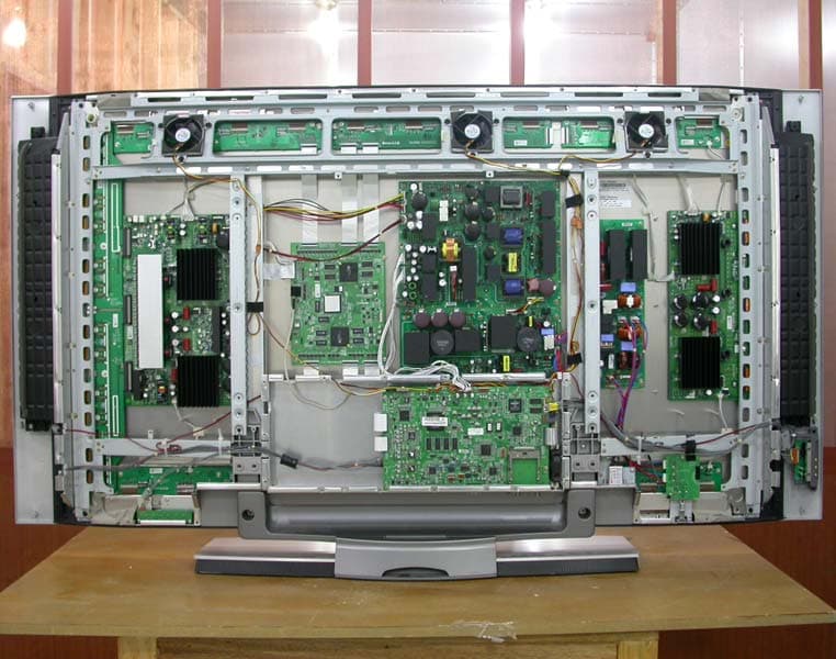
Click to zoom
Application Details
- Equipment Class
- JBP - Part 15 Class B Computing Device Peripheral
- Date of Grant
- May 30, 2005
- Application Purpose
- Original Equipment
- Date of Application
- May 30, 2005
- Equipment Note
- PDP Display
- Company
- LG Electronics USA, Inc.
- Country
- United States
Documents & Files
Document Text
Text extracted from the exhibit documents filed with the FCC. Open a document above to read the original.
Users Manual
Owner’s Manual 15 •Component Input ports To get better picture quality, connect a DVD player to the compo- nent input ports as shown below. How to connect Connect the audio and video cables from the external equip- ment's output jacks to the TV input jacks, as shown in the figure. When connecting the TV to external equipment, match the jack colors (Video = yellow, Audio Left = white, and Audio Right = red). How to use 1. Select the input source with using the TV/VIDEObutton on the remote control. (If connected to A/V INPUT , select Video input source). 2. Operate the corresponding external equipment. Refer to external equipment operating the tv guide on screen system. Component ports on the TV Y P B PR Video output ports on DVD player Y Y Y Y Pb B-Y Cb P B Pr R-Y Cr P R How to connect 1. Connect the DVD video outputs (Y, PB, PR) to the COMPONENT (Y, PB, PR) INPUT jacks on the TV and connect the DVD audio outputs to the AUDIO INPUT jacks on the TV, as shown in the figure. 2. If your DVD only has an S-Video output jack, connect this to the S-VIDEO input on the TV and connect the DVD audio outputs to the AUDIO INPUT jacks on the TV, as shown in the figure. Note:If your DVD player does not have component video output, use S-Video. How to use 1. Turn on the DVD player, insert a DVD. 2. Use the TV/VIDEOorCOMP/RGB/HDMIbutton on the remote control to select Component 1 orComponent 2. (If connected to S-VIDEO, select the Video orFront Videoexternal input source.) 3. Refer to the DVD player's manual for operating instructions. External External A/V Source Setup A/V Source Setup DVD Setup DVD Setup CABLE Cable ANTENNA AC INPUT RL AUDIOVIDEO DVI COMPONENT2 DIGITAL AUDIO(OPTICAL) VIDEO INPUT AUDIO INPUT HDMI / DVI(VIDEO) AC INPUTAC INPUT B R (R) AUDIO (L) DIGITAL AUDIO OPTICAL (R) AUDIO (L) S-VIDEO CABLE Cable ANTENNA DVI COMPONENT2 DIGITAL AUDIO(OPTICAL) VIDEO INPUT AUDIO INPUT HDMI / DVI(VIDEO) DVD or Camcorder Video Game Set Notes: • Digital Audio will not work for Component 1 input source. • Digital Audio operation has priority if Digital Audio and AUDIO L/R are connected at the same time. or 16 Plasma TV Installation - This TV can receive Digital Over-the-air/Cable signals without an external digital set-top box. However, if you do receive Digital signals from a digital set-top box or other digital external device, refer to the figure as shown below. - This TV supports HDCP (High-bandwidth Digital Contents Protection) protocol for Digital Contents (480p,720p,1080i). How to connect Use the TV’s COMPONENT (Y, P B, PR) INPUT, RGB or HDMI/DVI jack for video connections, depending on your set-top box connector. Then, make the corresponding audio connections. How to use 1. Turn on the digital set-top box. (Refer to the owner’s manual for the digital set-top box.) 2. Use TV/VIDEOorCOMP/RGB/HDMIon the remote control to select Component 1,Component 2,RGB-DTV, or HDMI/DVIsource. HDSTB Setup HDSTB Setup AC INPUT (R) AUDIO (L) RGB-DTV OUTPUT B R (R) AUDIO (L) DIGITAL AUDIO OPTICAL (R) AUDIO (L) DVI-DTV OUTPUT DIGITAL AUDIO OPTICAL DVI COMPONENT2 DIGITAL AUDIO(OPTICAL) VIDEO INPUT AUDIO INPUT HDMI / DVI(VIDEO) CABLE Cable ANTENNA HDMI-DTV OUTPUT Digital Set-top Box or or or or Signal 480i 480p 720p 1080i Component 1/2 Ye s Ye s Ye s Ye s RGB-DTV,HDMI/DVI No Ye s Ye s Ye s CableCARD CableCARD TM TM Setup Setup AC INPUT CABLE Cable ANTENNA How to use Insert the CableCARD TM TM received from Cable Service provider to CableCARD TM TM slot of TV back panel. If Host or CableCARD TM TM does not display on the screen, contact with Cable service provider by phone. Note: • CableCARD TM TM has the types of Motorola, Scientific Atlanta, SCM etc.. These 3 types of CableCARD TM TM can be used for this PLASMA TV. Caution: When removing the CableCARD TM TM , do not fall it as this may cause impact to the CableCARD TM TM . Owner’s Manual 17 Installation How to connect 1. To get the best picture quality, adjust the PC graphics card to 1024x768, 60Hz. 2. Use the TV’s RGB INPUT or HDMI/DVI (Digital Visual Interface) INPUT port for video connections, depending on your PC con- nector. • If the graphic card on the PC does not output analog and digital RGB simultaneously, connect only one of either RGB INPUT or DVI INPUT to display the PC on the TV. • If the graphic card on the PC does output analog and digital RGB simultaneously, set the TV to either RGB or HDMI/DVI; (the other mode is set to Plug and Play automatically by the TV.) 3. Then, make the corresponding audio connections. If using a sound card, adjust the PC sound as required. How to use 1. Turn on the PC and the TV. 2. Turn on the display by pressing the POWER button on the TV's remote control. 3. Select RGB-PCorHDMI/DVIinput source in main input option of SETUP menu. (Refer to P.59) 4. Check the image on your TV. There may be noise associated with the resolution, vertical pattern, contrast or brightness in PC mode. If noise is present, change the PC mode to another resolution, change the refresh rate to another rate or adjust the brightness and contrast on the menu until the picture is clear. If the refresh rate of the PC graphic card can not be changed, change the PC graphic card or consult the manufacturer of the PC graphic card. Notes:• Depending on the graphics card, DOS mode may not work if you use a HDMI to DVI cable. • Avoid keeping a fixed image on the TV's screen for a long period of time. The fixed image may become permanently imprinted on the screen. Use the Orbiter screen saver when possible. • The synchronization input form for Horizontal and Vertical frequencies is separate. PC Setup PC Setup AC INPUT DVI COMPONENT2 DIGITAL AUDIO(OPTICAL) VIDEO INPUT AUDIO INPUT HDMI / DVI(VIDEO) CABLE Cable ANTENNA - This TV provides Plug and Play capability, meaning that the PC adjusts automatically to the TV's settings. - The TV perceives 640x480, 60Hz as DTV 480p based on the PC graphic card, change the screen scanning rate for the graphic card accordingly. Resolution…
Text truncated - open the document above for the full version.
Users Manual
Owner’s Manual 15 •Component Input ports To get better picture quality, connect a DVD player to the compo- nent input ports as shown below. How to connect Connect the audio and video cables from the external equip- ment's output jacks to the TV input jacks, as shown in the figure. When connecting the TV to external equipment, match the jack colors (Video = yellow, Audio Left = white, and Audio Right = red). How to use 1. Select the input source with using the TV/VIDEObutton on the remote control. (If connected to A/V INPUT , select Video input source). 2. Operate the corresponding external equipment. Refer to external equipment operating the tv guide on screen system. Component ports on the TV Y P B PR Video output ports on DVD player Y Y Y Y Pb B-Y Cb P B Pr R-Y Cr P R How to connect 1. Connect the DVD video outputs (Y, PB, PR) to the COMPONENT (Y, PB, PR) INPUT jacks on the TV and connect the DVD audio outputs to the AUDIO INPUT jacks on the TV, as shown in the figure. 2. If your DVD only has an S-Video output jack, connect this to the S-VIDEO input on the TV and connect the DVD audio outputs to the AUDIO INPUT jacks on the TV, as shown in the figure. Note:If your DVD player does not have component video output, use S-Video. How to use 1. Turn on the DVD player, insert a DVD. 2. Use the TV/VIDEOorCOMP/RGB/HDMIbutton on the remote control to select Component 1 orComponent 2. (If connected to S-VIDEO, select the Video orFront Videoexternal input source.) 3. Refer to the DVD player's manual for operating instructions. External External A/V Source Setup A/V Source Setup DVD Setup DVD Setup CABLE Cable ANTENNA AC INPUT RL AUDIOVIDEO DVI COMPONENT2 DIGITAL AUDIO(OPTICAL) VIDEO INPUT AUDIO INPUT HDMI / DVI(VIDEO) AC INPUTAC INPUT B R (R) AUDIO (L) DIGITAL AUDIO OPTICAL (R) AUDIO (L) S-VIDEO CABLE Cable ANTENNA DVI COMPONENT2 DIGITAL AUDIO(OPTICAL) VIDEO INPUT AUDIO INPUT HDMI / DVI(VIDEO) DVD or Camcorder Video Game Set Notes: • Digital Audio will not work for Component 1 input source. • Digital Audio operation has priority if Digital Audio and AUDIO L/R are connected at the same time. or 16 Plasma TV Installation - This TV can receive Digital Over-the-air/Cable signals without an external digital set-top box. However, if you do receive Digital signals from a digital set-top box or other digital external device, refer to the figure as shown below. - This TV supports HDCP (High-bandwidth Digital Contents Protection) protocol for Digital Contents (480p,720p,1080i). How to connect Use the TV’s COMPONENT (Y, P B, PR) INPUT, RGB or HDMI/DVI jack for video connections, depending on your set-top box connector. Then, make the corresponding audio connections. How to use 1. Turn on the digital set-top box. (Refer to the owner’s manual for the digital set-top box.) 2. Use TV/VIDEOorCOMP/RGB/HDMIon the remote control to select Component 1,Component 2,RGB-DTV, or HDMI/DVIsource. HDSTB Setup HDSTB Setup AC INPUT (R) AUDIO (L) RGB-DTV OUTPUT B R (R) AUDIO (L) DIGITAL AUDIO OPTICAL (R) AUDIO (L) DVI-DTV OUTPUT DIGITAL AUDIO OPTICAL DVI COMPONENT2 DIGITAL AUDIO(OPTICAL) VIDEO INPUT AUDIO INPUT HDMI / DVI(VIDEO) CABLE Cable ANTENNA HDMI-DTV OUTPUT Digital Set-top Box or or or or Signal 480i 480p 720p 1080i Component 1/2 Ye s Ye s Ye s Ye s RGB-DTV,HDMI/DVI No Ye s Ye s Ye s CableCARD CableCARD TM TM Setup Setup AC INPUT CABLE Cable ANTENNA How to use Insert the CableCARD TM TM received from Cable Service provider to CableCARD TM TM slot of TV back panel. If Host or CableCARD TM TM does not display on the screen, contact with Cable service provider by phone. Note: • CableCARD TM TM has the types of Motorola, Scientific Atlanta, SCM etc.. These 3 types of CableCARD TM TM can be used for this PLASMA TV. Caution: When removing the CableCARD TM TM , do not fall it as this may cause impact to the CableCARD TM TM . Owner’s Manual 17 Installation How to connect 1. To get the best picture quality, adjust the PC graphics card to 1024x768, 60Hz. 2. Use the TV’s RGB INPUT or HDMI/DVI (Digital Visual Interface) INPUT port for video connections, depending on your PC con- nector. • If the graphic card on the PC does not output analog and digital RGB simultaneously, connect only one of either RGB INPUT or DVI INPUT to display the PC on the TV. • If the graphic card on the PC does output analog and digital RGB simultaneously, set the TV to either RGB or HDMI/DVI; (the other mode is set to Plug and Play automatically by the TV.) 3. Then, make the corresponding audio connections. If using a sound card, adjust the PC sound as required. How to use 1. Turn on the PC and the TV. 2. Turn on the display by pressing the POWER button on the TV's remote control. 3. Select RGB-PCorHDMI/DVIinput source in main input option of SETUP menu. (Refer to P.59) 4. Check the image on your TV. There may be noise associated with the resolution, vertical pattern, contrast or brightness in PC mode. If noise is present, change the PC mode to another resolution, change the refresh rate to another rate or adjust the brightness and contrast on the menu until the picture is clear. If the refresh rate of the PC graphic card can not be changed, change the PC graphic card or consult the manufacturer of the PC graphic card. Notes:• Depending on the graphics card, DOS mode may not work if you use a HDMI to DVI cable. • Avoid keeping a fixed image on the TV's screen for a long period of time. The fixed image may become permanently imprinted on the screen. Use the Orbiter screen saver when possible. • The synchronization input form for Horizontal and Vertical frequencies is separate. PC Setup PC Setup AC INPUT DVI COMPONENT2 DIGITAL AUDIO(OPTICAL) VIDEO INPUT AUDIO INPUT HDMI / DVI(VIDEO) CABLE Cable ANTENNA - This TV provides Plug and Play capability, meaning that the PC adjusts automatically to the TV's settings. - The TV perceives 640x480, 60Hz as DTV 480p based on the PC graphic card, change the screen scanning rate for the graphic card accordingly. Resolution…
Text truncated - open the document above for the full version.
Users Manual
46 Plasma TV TV Guide On Screen System TV Guide On Screen TV Guide On Screen ® System continued System continued - After you initially complete Guide Setup, you can make changes to Guide settings in the following areas: • Change System Settings • Change Channel Display • Change Default Options Highlight a choice, press ENTER, and follow the on-screen instruc- tions. • Change System Settings This option appears after you have completed the initial Guide Setup process. PressENTERto display the Confirming Your Settings screen. You see your current settings. Choose one of the options, press ENTER, and follow the on-screen instructions. V< Setup > With Setup highlighted, press the Infobutton to display a Help screen. Press the Infobutton again to close the screen. Owner’s Manual 47 TV Guide On Screen System PressENTERto display the Channel Editor screen. Then, highlight a channel and press Menu. A Grid Options menu is displayed. Highlight Go Back to Setup to close the menu, change no information, and return to the Setup Service Bar. Or make changes and when finished, press ENTERto high- light Done. Press ENTERagain to close the menu and accept the changes. Highlight Cancel to close the menu, change no information, and return to the highlighted channel. • Change Channel Display Change Channel Display lets you edit channel information that appears in Listings. With Change Channel Display you can : •Re-order the position or the channel appears in Listings •Change the tune channel number •Switch a channel W On - the channel is always displayed W Off - the channel is never displayed W Auto-Hide - the channel is only displayed when program information is available. TV Guide On Screen TV Guide On Screen ® System continued System continued 48 Plasma TV TV Guide On Screen System General Default Options lets you set defaults for the following: •The initial Info Box size when the TV guide on screen system is entered. Choices are No, Small, Large, and Last Used (Default = Last Used). •The Info Box size rotation when the Info key is pressed while in the TV guide on screen system. Choices are No only, Small only, Large only, No & Small, No & Large, Small & Large, All (Default = All) •Automatic entry into the TV guide on screen system (Auto-Guide) when the TV is powered On. Choices are On and Off (Default = On). Highlight General Default Options, and press the Menu key to dis- play the General Default Options menu. Highlight Go to Service Bar to close the menu, change no infor- mation, and return to the Setup Service Bar. When finished, press ENTERto highlight Done. Press ENTER again to close the menu and accept the changes. Highlight Cancel to close the menu, change no information, and return to the highlighted option. • Change Default Options Change Default Options lets you change default settings in the following categories: •General Default Options •Record Defaults •Remind Defaults Highlight Change Default Options, and press ENTER. <General Default Options> TV Guide On Screen TV Guide On Screen ® System continued System continued Owner’s Manual 49 TV Guide On Screen System < Record Defaults> Record Default Options lets you set defaults for the following: • When to start the record event. Choices are 120 minutes early to 120 minutes late, to On time. (Default = On time) • When to end the record event. Choices are 120 minutes early to 120 minutes late, to On time. (Default = On time) • Recorder choice: Please choose the VCR only. This TV does not provide other devices with a recording feature. Highlight Record Defaults, and press the Menu key to display the Record Default Options menu. Highlight Go to Service Bar to close the menu, change no infor- mation, and return to the Setup Service Bar. TV Guide On Screen TV Guide On Screen ® System continued System continued < Remind Defaults> Remind Default Options lets you set defaults for the following: •Power On the TV, if Off, when a Reminder is scheduled. Choices are Yes and No. (Default = No) •Automatically tune the TV to the channel (TV must be On), when a Reminder is scheduled. Choices are Yes and No. (Default = No) •When to display the reminder screen. Choices are 30 seconds to 15 minutes early, to 30 seconds to 15 minutes late, to On time. (Default = 1 min early) Highlight Remind Defaults, and press the Menu key to display the Remind Default Options menu. Highlight Go to Service Bar to close the menu, change no infor- mation, and return to the Setup Service Bar. When finished, press ENTERto highlight Done. Press ENTER again to close the menu and accept the changes. Highlight Cancel to close the menu, change no information, and return to the highlighted option. 50 Plasma TV TV Guide On Screen System WOnce—records the show one time WRegularly—records the show every time the show airs on the same channel and starts at the same time WWeekly—records the show each time the show airs on the same day of the week, on the same channel and starts at the same time WOff (not cancel)—keeps the show in the list but will not record this show until the frequency is changed WCancel (no icon displayed)—does not record TV Guide On Screen TV Guide On Screen ® System continued System continued Record Record And Remind Features And Remind Features V< Record > You can set a show to Record in Listings, Search, and Schedule or change Record settings for a show in Schedule. There are 3 ways to set a show to Record: 1) Using the Record Button on the Remote • Press the Record button on the remote to record the show Once with current default settings (Start and End recording On Time). Each time you press the Record button, you change the record frequency (but not the default settings) among Once (default), Regularly, Daily, Weekly and then Cancel. Note: The proper Record icon appears on the show tile, as the Record button is pressed. 2) From a Panel Menu •Highlight a show, and press Menu to display the Episode Options menu. •Highlight Set Recording, and press ENTERto display the Reco…
Text truncated - open the document above for the full version.
Cover Letter(s)
LG Electronics Inc. 642 Jinpyoung-dong, Kumi-city, Kyoungsangbuk-do, 730-360,Korea TEL : +82-54-470-4537 FAX : 82-54-470-4534 Federal Communications Commission Authorization and Evaluation Division FCC ID : BEJDU60PY10 Confidentiality Request Pursuant to Sections 0.457 and 0.459 of the Commission’s Rules, the Applicant hereby requests confidential treatment of information accompanying this Application as outlined below: Schematics Block Diagram The above materials contain trade secrets and proprietary information not customarily released to the public. The public disclosure of these matters might be harmful to the Applicant and provide unjustified benefits to its competitors. The Applicant understands that pursuant to Rule 0.457, disclosure of this Application and all accompanying documentation will not be made before the data of the Grant for this application. Sincerely, Sang-Wook Lee/ Manager Engineer LG Electronics Inc. TEL : +82-54-470-4537 FAX : 82-54-470-4534
Cover Letter(s)
FCC ID : BEJDU60PY10 POWER OF ATTORNEY To whom it may concern: We the undersigned LG Electronics Inc. hereby authorize ESTECH Co., Ltd.(EST) of Korea to act on our behalf in all matters relating to all processes required in the FCC Part 15C approval and any communication needed with the national authority. Any and all acts carried out by EST on our behalf shall have the same effects as acts of our own. If you have any questions regarding the authorization, please don’t hesitate to contact us. Sincerely yours, Sign: Sang-Wook Lee/Manager Engineer Tel:82-54-470-4537 Fax: 82-54-470-4534
Cover Letter(s)
American Telecommunications Certification Body Inc. 6731 Whittier Ave, McLean, VA 22101 May 25, 2005 RE: LG Electronics USA FCC ID: BEJDU60PY10 After a review of the submitted information, I have a few comments on the above referenced Application. 1) The label does not appear to be properly labeled with “FCC ID: BEJDU60PY10”. Please review and correct. 2) ANSI C63.4 (2001) is mentioned several times in the report. Please note that ANSI C63.4 (2001) is not considered an acceptable test method under Part 15. Please reference Part 15.31: (a))(3) Other intentional and unintentional radiators are to be measured for compliance using the following procedure excluding sections 4.1.5.2, 5.7, 9 and 14: ANSI C63.4–2003: “Methods of Measurement of Radio-Noise Emissions from Low-Voltage Electrical and Electronic Equipment in the Range of 9 kHz to 40 GHz” (incorporated by reference, see §15.38). This incorporation by reference was approved by the Director of the Federal Register in accordance with 5 U.S.C. 552(a) and 1 CFR part 51. Note to paragraph (a)(3): Digital devices tested to show compliance with the provisions of §§15.107(e) and 15.109(g) must be tested following the ANSI C63.4 procedure described in paragraph (a)(3) of this section. Please review and correct as necessary. 3) Please comment on the RBW/VBW used during radiated testing. 4) It appears that ferrites were present on the RGB and DVI cables. Therefore these are expected to be supplied to the end user with the device. However the information on page 11 and 21 suggest these cables will not be provided. Please address. 5) FYI....This application only covered the PC peripheral portion of the device. Please note that the manufacturer is still responsible for making sure that the technical requirements for TV receivers have been verified per the FCC rules (these may be found in Sections 15.31(n), 15.107, 109, 111, 117, 118, 119,120, and 122 as applicable). Timothy R. Johnson Examining Engineer mailto: [email protected] The items indicated above must be submitted before processing can continue on the above referenced application. Failure to provide the requested information may result in application termination. z Page 2 May 27, 2005 Correspondence should be considered part of the permanent submission and may be viewed from the Internet after a Grant of Equipment Authorization is issued. Please do not respond to this correspondence using the email reply button. In order for your response to be processed expeditiously, you must submit your documents through the AmericanTCB.com website. Also, please note that partial responses increase processing time and should not be submitted. Any questions about the content of this correspondence should be directed to the sender.
Cover Letter(s)
American Telecommunications Certification Body Inc. 6731 Whittier Ave, McLean, VA 22101 May 27, 2005 RE: LG Electronics USA FCC ID: BEJDU60PY10 After a review of the submitted information, I have a few comments on the above referenced Application. 1) The new label provided still does not appear to be properly labeled with “FCC ID: BEJDU60PY10”. The term “FCC ID:” is missing from the label. Please review and correct. 2) Please comment on the RBW/VBW used during radiated testing. 3) It appears that ferrites were present on the RGB and DVI cables. Therefore these are expected to be supplied to the end user with the device. However the information on page 11 suggests these cables will not be provided. Please address. 4) FYI....This application only covered the PC peripheral portion of the device. Please note that the manufacturer is still responsible for making sure that the technical requirements for TV receivers have been verified per the FCC rules (these may be found in Sections 15.31(n), 15.107, 109, 111, 117, 118, 119,120, and 122 as applicable). Timothy R. Johnson Examining Engineer mailto: [email protected] The items indicated above must be submitted before processing can continue on the above referenced application. Failure to provide the requested information may result in application termination. Correspondence should be considered part of the permanent submission and may be viewed from the Internet after a Grant of Equipment Authorization is issued. Please do not respond to this correspondence using the email reply button. In order for your response to be processed expeditiously, you must submit your documents through the AmericanTCB.com website. Also, please note that partial responses increase processing time and should not be submitted. Any questions about the content of this correspondence should be directed to the sender.
Cover Letter(s)
Dear Timothy R. Johnson How are you. 1)I upload revised test report and label.(ANSI C63.4-2001=> ANSI C63.4- 2003) 2)We tested radiation emission by emi test receiver. 3)we tested without ferrites in dvi mode.Only ferrites are in RGB mode. -I will talk with LG Electronics about Monitor Cable. I will send revised manaual to TCB. I' m sorry Thank you, Yang. -----Original Message----- >From: Timothy R. Johnson [mailto:[email protected] ] >Sent: Friday, May 27, 2005 1:05 PM >To: [email protected] >Cc: [email protected] >Subject: Review of LG Electronics, FCC ID: BEJDU60PY10 > >Hyan Sook Yoon, > >Attached are comments regarding review of this application. Please >provide >information as soon as possible. > >Thank You, > > >Timothy R. Johnson >NARTE Certified EMC Engineer >No. EMC-002205-NE > >email: [email protected] >alternate email: [email protected] > >Attachment Converted: "c:\documents and settings\tim johnson\my documents\atcb folder\eudora\attach\ATCB Comments 0526051.pdf" From: =?ks_c_5601-1987?B?vufB+Ljw?= <[email protected]> To: <[email protected]> Subject: FW: Review of LG Electronics, FCC ID: BEJDU60PY10
Cover Letter(s)
Dear Timothy R. Johnson, 1)I upload revised id label(final) and manauals(final) 2)We tested radiation emission by emi test receiver. 3)we tested without ferrites in dvi mode.Only ferrites are in RGB mode. thank you, Yang. -----Original Message----- >From: ¾çÁø ̧ð [mailto:[email protected] ] >Sent: Friday, May 27, 2005 4:57 PM >To: '[email protected]' >Subject: FW: Review of LG Electronics, FCC ID: BEJDU60PY10 > >Dear Timothy R. Johnson > >How are you. >1)I upload revised test report and label.(ANSI C63.4-2001=> ANSI C63.4- >2003) >2)We tested radiation emission by emi test receiver. >3)we tested without ferrites in dvi mode.Only ferrites are in RGB mode. >-I will talk with LG Electronics about Monitor Cable. >I will send revised manaual to TCB. >I' m sorry > >Thank you, > >Yang. > > >-----Original Message----- >From: Timothy R. Johnson [mailto:[email protected] ] >Sent: Friday, May 27, 2005 1:05 PM >To: [email protected] >Cc: [email protected] >Subject: Review of LG Electronics, FCC ID: BEJDU60PY10 > >Hyan Sook Yoon, > >Attached are comments regarding review of this application. Please >provide >information as soon as possible. > >Thank You, > > >Timothy R. Johnson >NARTE Certified EMC Engineer >No. EMC-002205-NE > >email: [email protected] From: =?ks_c_5601-1987?B?vufB+Ljw?= <[email protected]> To: <[email protected]> Subject: FW: Review of LG Electronics, FCC ID: BEJDU60PY10 >alternate email: [email protected] > >Attachment Converted: "c:\documents and settings\tim johnson\my documents\atcb folder\eudora\attach\ATCB Comments 0526054.pdf"
External Photos
1. FRONT 2. REAR 3. PORT 4. PORT 4. INTERNAL
Internal Photos
INTERNAL PHOTO 1. MAIN 1.1 Front 1.2 Rear 2. POWER 2.1 Front 2.2 Rear 3. CTRL_LVDS 3.1 Front 3.2 Rear 4.PDP 4.1 Front 4.2 Rear 5. RGB 5.1 Front 5.2 Rear 6. YSUS 6.1 Front 6.2 Rear 7. Z SUS 7.1 Front 7.2 Rear 8. POWER SUB1 8.1 Front 8.2 Rear 9. POWER SUB2 9.1 Front 9.2 Rear 9. TUNNER 9.1 Front 9.2 Rear
Operational Description
LG Electronics Inc. FCC ID BEJDU60PY10 -Operational description- A plasma display panel is the latest display technology. It is currently the best way to achieve flat panel displays with excellent image quality and large screen sizes, that are easily viewable. The PDP can be thought of as a descendant of the neon lamp an dit can be also be viewed as a series of fluorescent lamps. PDP is an array of cells, known as pixels, which are comprised of 3 sub pixels, corresponding to the colors red, green, and blue. Gas in a plasma state is used to react with phosphors in each sub-pixel to produce colored light (red, green, or blue). These phos-phors are the same types used in Cathode Ray Tube (CRT) devices such as televisions and common computer monitors. You get the rich, dynamic colors that you expect. Each sub-pixel is individually controlled by advanced electronics to produce over16 million different colors. All of this means that you get perfect images that are easily viewable in a display that is less than 5inches thick.
Test Report
Compliance Test Report for FCC Company name Address Telephone Product name Model No. Serial No. Test date Testing location Standard □ Class A ■ Class B Test resultOK □ Class A ■ Class B Test resultOK Tested by Reviewed by Abbreviation * Note - This test report is not permitted to copy partly without our permission - This test result is dependent on only equipment to be used - This test result based on a single evaluation of one sample of the above mentioned OK, Pass = Passed, Fail = Failed, N/A = not applicable LG Electronics USA 2000 Millbrook Dr Lincolnshire, IL 60069 United states 847-941-8373 Measurement facility registration number Engineer J.H.Kim Manager Engineer J.M.Yang 94696 (Signature) (Signature) Date of issue ESTECH. Co., Ltd. 97-1 Hoiuk-Ri Majang-Myon, Icheon-city, KyungKi-Do, Korea Test item ■ Conducted Emission ■ Radiated Emission FCC PART 15 2002 , ANSI C 63.4 200 2005-05-23 ~2005-05-25 DU-60PY10 NONE LG Electronics Inc. KOREA Report Number : ESTF150505-006 , Web : www. estech. co. kr Page 1 of 14 Report NumberESTF150505-006 Manufacturer Country of origin Applicant Product 2005-05-25 PLASMA MONITOR 3 4 5 6 8 8 8 9 10 10 10 11 12 14 Appendix 1. Spectral diagram Appendix 2. Phorographs of EUT in side PCB Appendix 3. Block diagram of EUT Appendix 4. Circuit Diagram 7. Photogra phs of test setup ........................................................................... 8. Photogra phs of EUT .................................................................................... 6. Measurement of conducted emission ............................................................ 6.1 Measurement e quipment ....................…
Text truncated - open the document above for the full version.
Contact Information
Applicant
David Kim(Team leader, LGEUS NA Policy & Regulatory Affairs)
Technical Contact
LG ElectronicsSang-wook Lee
[email protected]82-54-470-4537
642 Jinpyoung-dong · Kumi-city Kyoungsangbuk-do · South Korea
Non-Technical Contact
LG ElectronicsSang-wook Lee
[email protected]82-54-470-4537
Test Firm
Estech Co., Ltd.Ike Chung
Technical Specifications
| # | Rule Parts | Frequency Range | Power Output |
|---|---|---|---|
| 1 | 15B | - | - |
Other Applications from LG Electronics USA, Inc.

BEJTFHOBINI1F1
Jan 08, 2025Telematics
Equipment Class
DTS - Digital Transmission SystemBEJNT-16Z90TS
Oct 02, 2024Notebook Computer
Equipment Class
DSS - Part 15 Spread Spectrum TransmitterBEJSP-PEW8
Sep 26, 2024Stylus Pen
Equipment Class
DCD - Part 15 Low Power Transmitter Below 1705 kHzBEJ-RSMV2
Sep 24, 2024RF Module
Equipment Class
FDS - Part 15 Field Disturbance SensorBEJTFBMEIBN3EU
Sep 24, 2024Telematics
Equipment Class
NII - Unlicensed National Information Infrastructure TX