BEJGT8320CDigital Spread Spectrum Cordless Telephone
LG Electronics USA, Inc.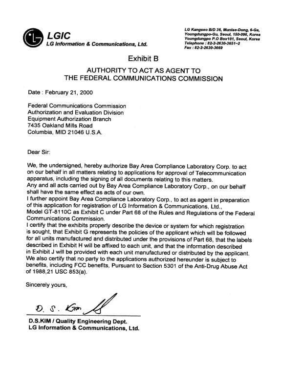
Click to zoom
Application Details
- Equipment Class
- DSS - Part 15 Spread Spectrum Transmitter
- Date of Grant
- Feb 15, 2001
- Application Purpose
- Original Equipment
- Date of Application
- Feb 15, 2001
- Equipment Note
- Digital Spread Spectrum Cordless Telephone
- Frequency Range
- 904.00000000 - 926.00000000
- Company
- LG Electronics USA, Inc.
- Country
- United States
Documents & Files
Document Text
Text extracted from the exhibit documents filed with the FCC. Open a document above to read the original.
Users Manual
Note: This report may not be duplicated without prior written consent of Bay Area Compliance Laboratory Corporation. This report must not be used by the client to claim product endorsement by NVLAP or any agency of the U.S. Government. FCC PART 15 Subpart C EUT Users Manual FOR LG Electronics Inc. LG Kangseo B/D 36, Munlae-Dong, 6-Ga, Youngdungpo-Gu, Seoul, 150-096, Korea FCC ID: BEJGT8320C October 30, 2000 This Report Concerns: Original Report Equipment Type: Digital Spread Spectrum Cordless Phone – Household Appliances Test Engineer: Hien Pham Test Date: October 12, 2000 Reviewed By: John Y. Chan – Engineering Manager Prepared By: Bay Area Compliance Laboratory Corporation 230 Commercial Street, Suite 2 Sunnyvale, CA 94086 Tel: (408) 732-9162 Fax: (408) 732-9164 LG Electronics Inc. FCC ID: BEJGT8320C Report # EUT User manual Page 2 of 40 FCC Part 15 Subpart C Test Report TABLE OF CONTENTS 1 - GENERAL INFORMATION.................................................................................................................................................3 1. 1.1 PRODUCT DESCRIPTION FOR EQUIPMENT UNDER TEST (EUT)....................................................................................3 1.2 OBJECTIVE................................................................................................................................................................................3 1.3 RELATED SUBMITTAL(S)/GRANT(S).....................................................................................................................................3 1.4 TEST METHODOLOGY..............................................................................................................................................................3 1.5 TEST FACILITY.........................................................................................................................................................................4 1.6 TEST EQUIPMENT LIST............................................................................................................................................................4 1.7 EQUIPMENT UNDER TEST (EUT)...........................................................................................................................................5 1.8 EUT CONFIGURATION DETAILS AND LIST...........................................................................................................................5 1.9 EXTERNAL I/O CABLING........................................................................................................................................................5 APPENDIX A – AGENT AUTHORIZATION LETTER....................................................................................................6 APPENDIX B – USER MANUAL..............................................................................................................................................8 FCC PART 15 WARNING:..............................................................................................................................................................9 D.S.KIM / QUALITY ENGINEERING DEPT...................................................................................................10 USER’S MANUAL........................................................................................................................................................................12 GETTING TO KNOW YOUR NEW PHONE......................................................................................................................14 USING YOUR PHONE...............................................................................................................................................................24 THE INTEGRATED ANSWERING DEVICE.....................................................................................................................29 USING CALLER ID AND CALL WAITING ID.................................................................................................................32 VOICE MAIL.................................................................................................................................................................................35 LG Electronics Inc. FCC ID: BEJGT8320C Report # EUT User manual Page 3 of 40 FCC Part 15 Subpart C Test Report 1 - GENERAL INFORMATION 1. 1.1 Product Description for Equipment Under Test (EUT) The LG Electronics Inc., FCC ID BEJGT8320C or the "EUT" as referred to in this report is a Digital Spread Spectrum Cordless Phone which has 20 channel possible in the 904-926 MHz Bandwidth, and the transmission range up to 1 Km in open sight (longer range than analog 900MHz cordless phone). The EUT was composed of two parts: one is the handset which measures 9” L x 2.125” W x 1.675” H, the other is the base which measures 7” L x 5.5” W x 2.25” H. 1.2 Objective This type approval report is prepared on behalf of LG Electronics Inc. in accordance with Part 2, Subpart J, Part 15, Subparts A and B of the Federal Communication Commissions rules. The objective of the manufacturer is to demonstrate compliance with FCC rules for Output Power, 6 dB Bandwidth, Power Density, Band Edge, Spurious Emission, Processing Gain, Antenna Gain, and Conducted and Radiated Emission. 1.3 Related Submittal(s)/Grant(s) No Related Submittals 1.4 Test Methodology All measurements contained in this report were conducted with ANSI C63.4 –1992, American National Standard for Methods of Measurement of Radio-Noise Emissions from Low-Voltage Electrical and Electronic Equipment in the range of 9 kHz to 40 GHz. All radiated and conducted emissions measurement was performed at Bay Area Compliance Laboratory, Corp. The radiated testing was performed at an antenna-to-EUT distance of 3 meters. LG Electronics Inc. FCC ID: BEJGT8320C Report # EUT User manual Page 4 of 40 FCC Part 15 Subpart C Test Report 1.5 Test Facility The Open Area Test Site used by Ba…
Text truncated - open the document above for the full version.
External Photos
Note: This report may not be duplicated without prior written consent of Bay Area Compliance Laboratory Corporation. This report must not be used by the client to claim product endorsement by NVLAP or any agency of the U.S. Government. FCC PART 15 Subpart C EUT External Photos FOR LG Electronics Inc. LG Kangseo B/D 36, Munlae-Dong, 6-Ga, Youngdungpo-Gu, Seoul, 150-096, Korea FCC ID: BEJGT8320C October 30, 2000 This Report Concerns: Original Report Equipment Type: Digital Spread Spectrum Cordless Phone – Household Appliances Test Engineer: Hien Pham Test Date: October 12, 2000 Reviewed By: John Y. Chan – Engineering Manager Prepared By: Bay Area Compliance Laboratory Corporation 230 Commercial Street, Suite 2 Sunnyvale, CA 94086 Tel: (408) 732-9162 Fax: (408) 732-9164 LG Electronics Inc. FCC ID: BEJGT8320C Report # EUT External photo Page 2 of 10 FCC Part 15 Subpart C Test Report TABLE OF CONTENTS 1 - GENERAL INFORMATION.................................................................................................................................................3 1.1 PRODUCT DESCRIPTION FOR EQUIPMENT UNDER TEST (EUT)........................................................................................3 1.2 OBJECTIVE................................................................................................................................................................................3 1.3 RELATED SUBMITTAL(S)/GRANT(S).....................................................................................................................................3 1.4 TEST METHODOLOGY..............................................................................................................................................................3 1.5 TEST FACILITY.........................................................................................................................................................................4 1.6 TEST EQUIPMENT LIST............................................................................................................................................................4 1.7 EQUIPMENT UNDER TEST (EUT)...........................................................................................................................................5 1.8 EUT CONFIGURATION DETAILS AND LIST...........................................................................................................................5 1.9 EXTERNAL I/O CABLING........................................................................................................................................................5 2 – EUT PHOTOGRAPHS...........................................................................................................................................................6 2.1 EUT – BASE TOP VIEW..........................................................................................................................................................6 2.2 EUT – HANDSET TOP VIEW...................................................................................................................................................7 2.3 EUT – OVERALL VIEW WITH POWER ADAPTER.................................................................................................................8 APPENDIX A – AGENT AUTHORIZATION LETTER....................................................................................................9 LG Electronics Inc. FCC ID: BEJGT8320C Report # EUT External photo Page 3 of 10 FCC Part 15 Subpart C Test Report 1 - GENERAL INFORMATION 1.1 Product Description for Equipment Under Test (EUT) The LG Electronic Inc., FCC ID BEJGT8320C or the "EUT" as referred to in this report is a Digital Spread Spectrum Cordless Phone which has 20 channel possible in the 904-926 MHz Bandwidth, and the transmission range up to 1 Km in open sight (longer range than analog 900MHz cordless phone). The EUT was composed of two parts: one is the handset which measures 9” L x 2.125” W x 1.675” H, the other is the base which measures 7” L x 5.5” W x 2.25” H. 1.2 Objective This type approval report is prepared on behalf of LG Electronics Inc. in accordance with Part 2, Subpart J, Part 15, Subparts A and B of the Federal Communication Commissions rules. The objective of the manufacturer is to demonstrate compliance with FCC rules for Output Power, 6 dB Bandwidth, Power Density, Band Edge, Spurious Emission, Processing Gain, Antenna Gain, and Conducted and Radiated Emission. 1.3 Related Submittal(s)/Grant(s) No Related Submittals 1.4 Test Methodology All measurements contained in this report were conducted with ANSI C63.4 –1992, American National Standard for Methods of Measurement of Radio-Noise Emissions from Low-Voltage Electrical and Electronic Equipment in the range of 9 kHz to 40 GHz. All radiated and conducted emissions measurement was performed at Bay Area Compliance Laboratory, Corp. The radiated testing was performed at an antenna-to-EUT distance of 3 meters. LG Electronics Inc. FCC ID: BEJGT8320C Report # EUT External photo Page 4 of 10 FCC Part 15 Subpart C Test Report 1.5 Test Facility The Open Area Test Site used by Bay Area Compliance Laboratory Corporation to collect radiated and conducted emission measurement data is located in the back parking lot of the building at 230 Commercial Street, Suite 2, Sunnyvale, California, USA. Test site at Bay Area Compliance Laboratory Corporation has been fully described in reports submitted to the Federal Communication Commission (FCC) and Voluntary Control Council for Interference (VCCI). The details of these reports has been found to be in compliance with the requirements of Section 2.948 of the FCC Rules on February 11 and December 10, 1997 and Article 8 of the VCCI regulations on December 25, 1997. The facility also complies with the radiated and AC line conducted test site criteria set forth in ANSI C63.4-1992. The Federal Communications Commission and V…
Text truncated - open the document above for the full version.
ID Label/Location Info
FCC ID: BEJGT8320C Privacy Statement on FCC Label: 230 Commercial St. Ste. Sunnyvale, CA 94086 Tel: (408)732-9162 Fax: (408)732-9164 http://www.baclcorp.com FCC ID : BEJGT8320CFCC ID : BEJGT8320C This Device complies with Part 15 of the FCC Rules. Operation is subject to the folloing two conditions:(1)this device may not cause harm- ful interference, and (2) this device must accept any interference received, including interference that may cause undesired operation. Privacy of communciations may not be ensured when using this phone. 2.1875" 1.0" FCC ID: BEJGT8320C Proposed Label Location on EUT 230 Commercial St. Ste. Sunnyvale, CA 94086 Tel: (408)732-9162 Fax: (408)732-9164 http://www.baclcorp.com EUT Base Bottom ViewFCC Label Location FCC ID : BEJGT8320C This Device complies with Part 15 of the FCC Rules. Operation is subject to the folloing two conditions:(1)this device may not cause harm- ful interference, and (2) this device must accept any interference received, including interference that may cause undesired operation. Privacy of communciations may not be ensured when using this phone. EUT Handset Rear View FCC Label Location FCC ID : BEJGT8320C This Device complies with Part 15 of the FCC Rules. Operation is subject to the folloing two conditions:(1)this device may not cause harm- ful interference, and (2) this device must accept any interference received, including interference that may cause undesired operation. Privacy of communciations may not be ensured when using this phone.
Internal Photos
Note: This report may not be duplicated without prior written consent of Bay Area Compliance Laboratory Corporation. This report must not be used by the client to claim product endorsement by NVLAP or any agency of the U.S. Government. FCC PART 15 Subpart C EUT Internal Photos FOR LG Electronics Inc. LG Kangseo B/D 36, Munlae-Dong, 6-Ga, Youngdungpo-Gu, Seoul, 150-096, Korea FCC ID: BEJGT8320C October 30, 2000 This Report Concerns: Original Report Equipment Type: Digital Spread Spectrum Cordless Phone – Household Appliances Test Engineer: Hien Pham Test Date: October 12, 2000 Reviewed By: John Y. Chan – Engineering Manager Prepared By: Bay Area Compliance Laboratory Corporation 230 Commercial Street, Suite 2 Sunnyvale, CA 94086 Tel: (408) 732-9162 Fax: (408) 732-9164 LG Electronics Inc. FCC ID: BEJGT8320C Report # EUT Internal photo Page 2 of 11 FCC Part 15 Subpart C Test Report TABLE OF CONTENTS 1 - GENERAL INFORMATION.................................................................................................................................................3 1.1 PRODUCT DESCRIPTION FOR EQUIPMENT UNDER TEST (EUT)........................................................................................3 1.2 OBJECTIVE................................................................................................................................................................................3 1.3 RELATED SUBMITTAL(S)/GRANT(S).....................................................................................................................................3 1.4 TEST METHODOLOGY..............................................................................................................................................................3 1.5 TEST FACILITY.........................................................................................................................................................................4 1.6 TEST EQUIPMENT LIST............................................................................................................................................................4 1.7 EQUIPMENT UNDER TEST (EUT)...........................................................................................................................................5 1.8 EUT CONFIGURATION DETAILS AND LIST...........................................................................................................................5 1.9 EXTERNAL I/O CABLING........................................................................................................................................................5 2 – EUT PHOTOGRAPHS...........................................................................................................................................................6 2.1 EUT BASE – ENCLOSURE OFF VIEW....................................................................................................................................6 2.2 EUT BASE ENCLOSURE OFF BOARD VIEW.......................................................................................................................7 2.3 EUT HANDSET ENCLOSURE VIEW........................................................................................................................................8 2.4 EUT HANDSET ENCLOSURE OFF BOARD VIEW..................................................................................................................9 APPENDIX A – AGENT AUTHORIZATION LETTER..................................................................................................10 LG Electronics Inc. FCC ID: BEJGT8320C Report # EUT Internal photo Page 3 of 11 FCC Part 15 Subpart C Test Report 1 - GENERAL INFORMATION 1.1 Product Description for Equipment Under Test (EUT) The LG Electronic Inc., FCC ID BEJGT8320C or the "EUT" as referred to in this report is a Digital Spread Spectrum Cordless Phone which has 20 channel possible in the 904-926 MHz Bandwidth, and the transmission range up to 1 Km in open sight (longer range than analog 900MHz cordless phone). The EUT was composed of two parts: one is the handset which measures 9” L x 2.125” W x 1.675” H, the other is the base which measures 7” L x 5.5” W x 2.25” H. 1.2 Objective This type approval report is prepared on behalf of LG Electronics Inc., in accordance with Part 2, Subpart J, Part 15, Subparts A and B of the Federal Communication Commissions rules. The objective of the manufacturer is to demonstrate compliance with FCC rules for Output Power, 6 dB Bandwidth, Power Density, Band Edge, Spurious Emission, Processing Gain, Antenna Gain, and Conducted and Radiated Emission. 1.3 Related Submittal(s)/Grant(s) No Related Submittals 1.4 Test Methodology All measurements contained in this report were conducted with ANSI C63.4 –1992, American National Standard for Methods of Measurement of Radio-Noise Emissions from Low-Voltage Electrical and Electronic Equipment in the range of 9 kHz to 40 GHz. All radiated and conducted emissions measurement was performed at Bay Area Compliance Laboratory, Corp. The radiated testing was performed at an antenna-to-EUT distance of 3 meters. LG Electronics Inc. FCC ID: BEJGT8320C Report # EUT Internal photo Page 4 of 11 FCC Part 15 Subpart C Test Report 1.5 Test Facility The Open Area Test Site used by Bay Area Compliance Laboratory Corporation to collect radiated and conducted emission measurement data is located in the back parking lot of the building at 230 Commercial Street, Suite 2, Sunnyvale, California, USA. Test site at Bay Area Compliance Laboratory Corporation has been fully described in reports submitted to the Federal Communication Commission (FCC) and Voluntary Control Council for Interference (VCCI). The details of these reports has been found to be in compliance with the requirements of Section 2.948 of the FCC Rules on February 11 and December 10, 1997 and Article 8 of the VCCI regulations on December 25, 1997. The facility also co…
Text truncated - open the document above for the full version.
Operational Description
Antenna Mounting From the EUT external and internal photographs, the antenna was soldered to the main board of EUT and then screwed down the main board. So no end user can replace it. It hence complies with the FCC 15.203 requirement. 230 Commercial St. Ste. Sunnyvale, CA 94086 Tel: (408)732-9162 Fax: (408)732-9164 http://www.baclcorp.com
Schematics
3.579545Mhz COL1 COL4COL3 COL2 058 STAR 4 REG VOL_L PAGE ANS 1 FLASH 6 SHAP PLAY 2 3 VOL_H 7 SPEAKER PAUSE MEMORY MEMO 9 RECORD
Test Report
Subject: Re: TCB Qestions Date: Wed, 29 Nov 2000 11:55:23 -0800 From: "Rita Cai" <[email protected]> To: "Roger J. Midgley" <[email protected]> ----- Original Message ----- From: Roger J. Midgley <[email protected]> To: <[email protected]> Sent: Thursday, November 16, 2000 10:22 AM Subject: TCB Qestions Roger, Thank you for the following message. My reply is in teal green color. Rita: Enclosed below are some questions regarding the applications CCL is reviewing for TCB certification on two cordless telephones: 1. The test setup block diagrams show that the handset and base station were tested separately; however, the test setup photos show both the base and handset on the table. Please resubmit photos that show each on the table separately. Please see the attached files. 2. The test procedure for the peak output power and the power spectral density indicates that an Attenuator and cable were used during the testing, but the plots for these test does not show how the loss of the Attenuator and cable were accounted for. Please indicate how the loss was accounted for on the plots submitted. We use HP internal attenuation and it was showed on the plot. The RF cable was very short and the loss was less than 0.5dB. 3. The RBW for the bandwidth test should be performed with a RBW of 100 kHz not the 1 MHz that was submitted. This test will not need to be repeated because it is clear that even with a RBW of 100 kHz the device will still meet the > 500 kHz requirement; however, in the future please perform with a RBW of 100 kHz. In the future, we will perform the test using a RBW of 100KHz. 4. Please re-measure and submit data for the bandedge compliance and conducted spurious emissions using a RBW of 100 kHz as per section 15.247 (c). When we did the test, we used 1MHz for RBW and VBW, and this data would be more stricted than 100MHz for RBW and VBW. Even with this setup, the data has a lot of margin and it met the respective requirements. However, later we will use 100MHz in our future tests. 5. Please indicate what RBW and VBW settings were used for both Peak and Average measurements of Radiated spurious emissions that fall within the restricted bands of 15.205. Also there was not and data submitted for the 5th, 8th and 9th harmonics that fall within the restricted bands, if there were was not any emissions detected please submit the noise floor file:///G|/WPDATA/TCB/PROJECTS/32-0014 Bay Area 8310/Response to Questions.txt file:///G|/WPDATA/TCB/PROJECTS/32-0014 Bay Area 8310/Response to Questions.txt (1 of 5) [12/8/2000 3:13:09 PM] reading of the spectrum analyzer to ensure that the noise floor of the measurement equipment capable of measurements below the specified limit. Above 1GHz, we used 1MHz for RBW and VBW (peak) while below 1GHz, we used 100KHz for RBW and VBW. The noise floor reading of the spectrum analyzer is 20dBuV for the 5th, 8th and 9th harmonics. 6. The frequency range that is listed in section 3.6.0 indicates "30 MHz - 90000 MHz" I believe this should be 9000 MHz. The typo has already been modified and the updated will be sent to you in the form of PDF. 7. The data sheet for radiated spurious emissions indicates that the amplifier gain is 20 dB, and the amplifier that is listed in the test equipment used on page 4 of the report is a HP 8447E power amplifier. The specification for the HP 8447E is a 22 dB gain and a frequency range of 0.01 MHz - 1300 MHz, if this is was the amplifier used for these measurements it should not be used above 1300 MHz. Please indicate what pre-amplifier was used for the radiated emissions above 1 GHz. Please note that depending on what pre-amplifier you use the gain can vary depending on the frequency and is not always a flat gain across the frequency of operation. For instance the HP 8449B pre-amplifier that we use for measurements between 1 GHz to 26.5 GHz indicates that the typical gain is 30 dB; however, the measured gain is anywhere from 32.5 dB to 38.2 dB. The amplifier which we used was HP8349B and the specification is 20dB gain from 2GHz to 20GHz. And also TEC, PA-102 amplifier covered from 1GHz to 2GHz. The gain is 20dB flat. 8. Please submit a block diagram for both the handset and base station. Please see the attached files. 9. Please indicate how the antenna connectors comply with section 15.203. The attenna was soldered in the main board and used a screw to screw in so that users can not change the attenna by themselves. 10. Please indicate how the device complies with the RF Exposure of section 15.247 (b)(4). Per FCC OET Bulletin 65 Supplement C, Evaluation Compliance with FCC Guidelines for Human Exposuer to Radiofrequency Electromagnetic Fields, Page 22 this device has output power less than 10dBuV which means less than 0.3W at 915MHz by the guidelines, it met the RF exposure limits and the manufacturer does not mean to put the special instruction or warning statement in the user manual. 11. Please submit a Theory of Operation that describes how the device operates to determine if it operates as a Direct Sequence Spread Spectrum device. You could find the Theory of Operation in the user manual. file:///G|/WPDATA/TCB/PROJECTS/32-0014 Bay Area 8310/Response to Questions.txt file:///G|/WPDATA/TCB/PROJECTS/32-0014 Bay Area 8310/Response to Questions.txt (2 of 5) [12/8/2000 3:13:09 PM] 12. There was not a request for confidentiality filed with this application as per section 0.459. If this is not requested then all of the exhibits will become public access once they are uploaded to the FCC website. The following exhibits can be held confidential, Exhibit 4 (block diagram), Exhibit 5 (schematics) and Exhibit 12 (Theory of Operation). The fee for the request for confidentiality is $140.00 and we must have any official request from the applicant. I have enclosed a sample request for confidentially that can be used, this must be on the applicants letterhead and signed. We do not require confidentiality for our application. -- Please let me know if I…
Text truncated - open the document above for the full version.
Test Report
Note: This report may not be duplicated without prior written consent of Bay Area Compliance Laboratory Corporation. This report must not be used by the client to claim product endorsement by NVLAP or any agency of the U.S. Government. 1 FCC PART 15 Subpart C EMI MEASUREMENT AND TEST REPORT FOR LG Electronics Inc. LG Kangseo B/D 36, Munlae-Dong, 6-Ga, Youngdungpo-Gu, Seoul, 150-096, Korea FCC ID: BEJGT8320C October 30, 2000 This Report Concerns: Original Report Equipment Type: Digital Spread Spectrum Cordless Phone – Household Appliances Test Engineer: Hien Pham Test Date: October 12, 2000 Reviewed By: John Y. Chan – Engineering Manager Prepared By: Bay Area Compliance Laboratory Corporation 230 Commercial Street, Suite 2 Sunnyvale, CA 94086 Tel: (408) 732-9162 Fax: (408) 732-9164 Exhibit 6 LG Electronics Inc. FCC ID: BEJGT8320C Report #r0010092 FCC Part 15 Subpart C Test Report Page 2 of 67 TABLE OF CONTENTS 1 - GENERAL INFORMATION..................................................................................................................................................3 1.1 PRODUCT DESCRIPTION FOR EQUIPMENT UNDER TEST (EUT) ........................................................................................3 1.2 OBJECTIVE................................................................................................................................................................................3 1.3 RELATED SUBMITTAL(S)/GRANT(S).....................................................................................................................................3 1.4 TEST METHODOLOGY..............................................................................................................................................................3 1.5 TEST FACILITY.........................................................................................................................................................................4 1.6 TEST EQUIPMENT LIST............................................................................................................................................................4 1.7 EQUIPMENT UNDER TEST (EUT)...........................................................................................................................................5 1.8 EUT CONFIGURATION DETAILS AND LIST...........................................................................................................................5 1.9 EXTERNAL I/O CABLING........................................................................................................................................................5 2 - SYSTEM TEST CONFIGURATION...................................................................................................................................6 2.1 JUSTIFICATION..........................................................................................................................................................................6 2.2 BLOCK DIAGRAM.....................................................................................................................................................................6 2.3 TEST SETUP BLOCK DIAGRAM...............................................................................................................................................7 2.4 EQUIPMENT MODIFICATIONS.................................................................................................................................................8 3.0 SUMMARY OF TEST RESULTS........................................................................................................................................9 3.1.0 PEAK OUTPUT POWER.........................................................................................................................................................9 3.2.0 6DB BANDWIDTH.....................................................................................................................…
Text truncated - open the document above for the full version.
Contact Information
Applicant
David Kim(Team leader, LGEUS NA Policy & Regulatory Affairs)
Technical Contact
Communication Certification LaboratoryScott B Earl
[email protected]801 972 6146
1940 W. Alexander St. · Salt Lake City, Utah · United States
Test Firm
Bay Area Compliance LaboratoryJohn Chan
Technical Specifications
| # | Rule Parts | Frequency Range | Power Output |
|---|---|---|---|
| 1 | 15C | 904 MHz - 926 MHz | 10.00 mW |
Other Applications from LG Electronics USA, Inc.

BEJTFHOBINI1F1
Jan 08, 2025Telematics
Equipment Class
DTS - Digital Transmission SystemBEJNT-16Z90TS
Oct 02, 2024Notebook Computer
Equipment Class
DSS - Part 15 Spread Spectrum TransmitterBEJSP-PEW8
Sep 26, 2024Stylus Pen
Equipment Class
DCD - Part 15 Low Power Transmitter Below 1705 kHzBEJ-RSMV2
Sep 24, 2024RF Module
Equipment Class
FDS - Part 15 Field Disturbance SensorBEJTFBMEIBN3EU
Sep 24, 2024Telematics
Equipment Class
NII - Unlicensed National Information Infrastructure TX